
Subscribe to Our Youtube Channel
Related Manuals for Keysight Infiniium 8000 Series


Summary of Contents for Keysight Infiniium 8000 Series
- Page 1 Service Guide Publication Number D8064- 97010 October 2015 © Copyright Keysight Technologies 2005- 2007, 2011, 2015 All Rights Reserved. 8000 Series Infiniium Oscilloscopes...
- Page 2 The Keysight Infiniium Oscilloscope Model 8000 Series at a Glance Ease of use with high performance Acquisition and general controls start and stop the oscilloscope and do basic setup The Keysight Technologies Infiniium oscilloscopes combine unprecedented ease-of-use with high- •Run and stop controls for continuous or single-...
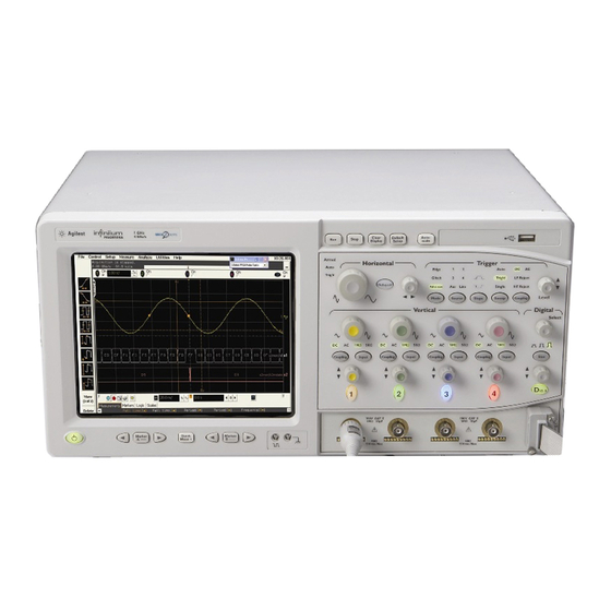
- Page 3 Touchscreen Horizontal Acquisition and USB 2.0 Display Controls General Controls Port Power Marker and Quick Vertical AutoProbe Vertical Trigger Trigger Digital Controls Digital Controls Measurement Controls Interface Inputs Setup Setup and Port (MSO and Port (MSO Controls models only) models only) 8000 Series Oscilloscope Front Panel...
- Page 4 Rear Foot Parallel CD-ROM GPIB Interface Optional Removable AC Power Printer Drive Port Hard Drive Input Port Mouse RS232 Video Line In Kensington Output Line Out Ports Trig Trig Equipment Keyboard Port Microphone Lock Ports 8000 Series Oscilloscope Back Panel Note: Your instrument’s back panel configuration may differ from this diagram.
- Page 5 In This Book This book provides the service documentation for the Keysight Technologies 8000- Series oscilloscopes. It is divided into eight chapters. Chapter 1, “General Information,” provides general information and specifications. Chapter 2, “Preparing for Use,” shows you how to prepare the oscilloscope for use.
-
Page 7: Table Of Contents
Contents General Information Instruments covered by this service guide To determine whether the oscilloscope is under warranty Accessories supplied Accessories available Options available Specifications & characteristics Environmental Conditions Measurement Category Oscilloscope Dimensions Preparing for Use To inspect package contents To connect power To connect the mouse, keyboard, LAN, printer, and GPIB cable To connect the standard 10073C probes To connect optional InfiniiMax oscilloscope probes... - Page 8 To setup the BIOS To troubleshoot the acquisition system Software Revisions Replacing Assemblies To return the oscilloscope to Keysight Technologies for service To remove and replace the top cover To remove and replace the bottom sleeve To disconnect and connect Mylar flex cables...
- Page 9 Instruments covered by this service guide Accessories supplied Options available Accessories available Specifications & characteristics General Information...
- Page 10 General Information This chapter of the Keysight Technologies Infiniium Oscilloscope Service Guide gives you general information about the oscilloscope. The following topics are covered in this chapter. • Instruments covered by this guide • Accessories • Options • Environmental category definitions...
-
Page 11: General Information
If you have an oscilloscope that was manufactured after the release of this manual, please check the Keysight Technologies website at www.keysight.com to see whether a newer version of this manual is available. You can perform a search for your oscilloscope’s model number, go to its product page, and select Library. -
Page 12: To Determine Whether The Oscilloscope Is Under Warranty
Direct your web browser to www.keysight.com/find/warrantystatus. If this URL no longer works because of changes to the www.keysight.com website, then search for “warranty status” at www.keysight.com to find the appropriate web page. -
Page 13: Accessories Supplied
• Accessory Pouch, P/N 54810- 68701 • Front Panel Cover, P/N 54810- 42201 • Power cord (see chapter 7, “Replaceable Parts,” for available power cords) • (4) Keysight 10073C 10:1 passive probes MSO standard accessories supplied • Probe Kit, P/N 54826- 68701... -
Page 14: Accessories Available
Chapter 1: General Information Accessories available Accessories available The following accessories are available for use with the Keysight Technologies Infiniium oscilloscope. Other accessories may be available. See your Keysight Technologies Sales Representative or visit www.keysight.com. Table 1-1 8000 Series Oscilloscope Accessories 1130A 1.5 GHz InfiniiMax Differential and Single-Ended Probe Amplifier... -
Page 15: Options Available
Options available Options available The following options are available for the Infiniium oscilloscope. Other options may be available. See your Keysight Technologies Sales Representative or visit www.keysight.com and perform a search for your oscilloscope’s model number. Table 1-2 8000 Series Oscilloscope Options... -
Page 16: Specifications & Characteristics
Specifications & characteristics For complete specifications and characteristics, direct your web browser to www.keysight.com and perform a search for the oscilloscope’s model number. Then select “Data Sheets” from the Library. Specifications that are pertinent to each test are given in the "Testing Performance"... -
Page 17: Environmental Conditions
Chapter 1: General Information Environmental Conditions Environmental Conditions Overvoltage Category This product is intended to be powered by MAINS that comply to Overvoltage Category II, which is typical of cord- and- plug connected equipment. Pollution Degree The 80000 Series Oscilloscope may be operated in environments of Pollution Degree 2 (or Pollution Degree 1). -
Page 18: Oscilloscope Dimensions
Chapter 1: General Information Oscilloscope Dimensions Oscilloscope Dimensions Figure 1-1 8000 Series Oscilloscope Dimensions. -
Page 19: Preparing For Use
To inspect package contents To connect power To connect the mouse, keyboard, LAN, printer, and GPIB cable To connect optional InfiniiMax oscilloscope probes To connect the digital probe Digital probe lead set To tilt the oscilloscope upward for easier viewing To turn on the oscilloscope To turn off the oscilloscope To verify basic oscilloscope operation... -
Page 20: To Inspect Package Contents
• Keyboard • Power cord (See page 139) • User’s Quick Start Guide If anything is missing, contact your nearest Keysight Technologies Sales Office. If the shipment was damaged, contact the carrier, then contact the nearest Keysight Technologies Sales Office. - Page 21 Chapter 2: Preparing for Use To inspect package contents Figure 2-1 Package Contents for the 8000 Series Infiniium Oscilloscopes Infiniium Oscilloscope with Accessory Pouch Front Panel Cover Keyboard Touchscreen Stylus Mouse Digital Probe (MSO models only) User’s Quick Start Guide 10073C Probes SMT IC Clip (MSO models...
-
Page 22: To Connect Power
Chapter 2: Preparing for Use To connect power To connect power Position the oscilloscope where it will have sufficient clearance for airflow around the top, back, and sides. Position the oscilloscope so that it is not difficult to unplug the power cord. Figure 2-2 Minimum 39 mm Minimum 0 mm... - Page 23 100 to 240 VAC. Therefore, you do not need to adjust an input line voltage setting. The power cord provided is matched by Keysight Technologies to the country of origin of the order. Ensure that you have the correct line cord.
-
Page 24: To Connect The Mouse, Keyboard, Lan, Printer, And Gpib Cable
Chapter 2: Preparing for Use To connect the mouse, keyboard, LAN, printer, and GPIB cable To connect the mouse, keyboard, LAN, printer, and GPIB cable Mouse. Plug the mouse into the mouse connector on the back panel of the oscilloscope. While you can operate many oscilloscope functions using only the front-panel keys and knobs, you will need the mouse to access advanced oscilloscope functions through the graphical interface, or to find out more about the oscilloscope through the built-in... -
Page 25: To Connect The Standard 10073C Probes
Chapter 2: Preparing for Use To connect the standard 10073C probes To connect the standard 10073C probes Attach the probe connector to the desired oscilloscope channel or trigger input. Rotate the BNC connector until it slides on easily and push it straight on. Rotate the locking ring until it latches into place. -
Page 26: To Connect Optional Infiniimax Oscilloscope Probes
Chapter 2: Preparing for Use To connect optional InfiniiMax oscilloscope probes To connect optional InfiniiMax oscilloscope probes Attach the probe connector to the desired oscilloscope channel or trigger input. Push it straight on until it latches into place. Figure 2-6 Attaching the Probe Connector Connect the probe to the circuit of interest using the browser or other probing accessories. - Page 27 Chapter 2: Preparing for Use To connect optional InfiniiMax oscilloscope probes To disconnect the probe, push the small latch on top of the probe connector to the left, then pull the connector body away from the front panel of the oscilloscope without twisting it.
-
Page 28: To Connect The Digital Probe
To connect the digital probe To connect the digital probe The Keysight Mixed- Signal Oscilloscopes (MSOs) are the only oscilloscopes to fully integrate 16 digital timing channels with the analog oscilloscope channels. The digital clip lead marked clk (clock) is unused. All the other digital clip leads are used for the digital channels. -
Page 29: Digital Probe Lead Set
Chapter 2: Preparing for Use Digital probe lead set Digital probe lead set The digital clip lead marked clk (clock) is unused. All the other digital clip leads are used for the digital channels. The probe lead set has 16 digital channels with a ground lead for each channel. Figure 2-10 Digital Probe Lead Set If a 0.63 mm square pin or a 0.66 diameter round pin is installed on the circuit under... - Page 30 (see Figure 2- 11) must be used on all digital channels for this to be valid. For more information on digital probing solutions, search for document number 5968- 4632E on the Keysight Technologies web site at www.keysight.com. This document is titled “Probing Solutions for Logic Analysis Systems.” It appears under the heading...
- Page 31 Chapter 2: Preparing for Use Digital probe lead set “Data Sheets, Demonstrations & Catalogs.”...
-
Page 32: To Tilt The Oscilloscope Upward For Easier Viewing
Chapter 2: Preparing for Use To tilt the oscilloscope upward for easier viewing To tilt the oscilloscope upward for easier viewing Lift up the front of the oscilloscope, grasp the wire bail near the center, and pull it down and forward until it latches into place. Figure 2-14 Latching the Oscilloscope Front Feet... -
Page 33: To Turn On The Oscilloscope
Chapter 2: Preparing for Use To turn on the oscilloscope To turn on the oscilloscope The first time that you turn on the oscilloscope, you will need to accept the Microsoft end user license agreement for Windows XP if prompted to do so. Depress the power switch in the lower left corner of the oscilloscope front panel. -
Page 34: To Verify Basic Oscilloscope Operation
Chapter 2: Preparing for Use To verify basic oscilloscope operation To verify basic oscilloscope operation Connect an oscilloscope probe to channel 1. Attach the probe to the probe compensation output on the front panel of the oscilloscope. Use a probe grabber tip so you do not need to hold the probe. The probe compensation output is marked with a square wave symbol. -
Page 35: Installing Application Programs On Infiniium
• Symantec Norton AntiVirus Before installing any software, you should exit the oscilloscope application. If you install an application other than those which Keysight has tested, it is possible that it could break the oscilloscope application. This would require you to reinstall the oscilloscope application. -
Page 36: To Clean The Oscilloscope
Chapter 2: Preparing for Use To clean the oscilloscope To clean the oscilloscope • Clean the oscilloscope with a soft cloth dampened with a mild soap and water solution. C A U T I O N Do not use too much liquid in cleaning the oscilloscope. Water can enter the Infiniium front panel, damaging sensitive electronic components. -
Page 37: Testing Performance
Testing Interval Equipment Required Self- Test Verification Test Record Operating Hints Specifications Performance Test Procedures To test the DC calibrator Procedure To test input resistance Procedure To test time scale accuracy Procedure To test delta time measurement accuracy Procedure To test single cursor voltage measurement accuracy with offset Procedure To test bandwidth Equivalent Time Test... -
Page 38: Testing Interval
Testing Performance The procedures in this section test measurement performance using performance specifications. Testing Interval The performance test procedures may be performed for incoming inspection of the oscilloscope and should be performed periodically thereafter to ensure and maintain peak performance. The recommended test interval is yearly or every 2,000 hours of operation. -
Page 39: Operating Hints
For complete specifications and characteristics see the oscilloscope’s datasheet. The datasheet can be viewed by directing your web browser to www.keysight.com and performing a search for the oscilloscope’s model number. The datasheet will be in the “Library.” Performance Test Procedures Performance test procedures start with the next paragraph. -
Page 40: To Test The Dc Calibrator
Test Limits: - 2.4 v to +2.4 v, DC gain accuracy ±0.2% Equipment Required Equipment Critical Specifications Recommended Model/Part Digital Multimeter 0.1 mV resolution, better than 0.1% accuracy Keysight 34401A Cable Keysight 10503A Adapter BNC (f) to banana (m) Keysight 1251-2277 Procedure Connect the multimeter to the back panel Aux Out BNC. - Page 41 Chapter 3: Testing Performance To test the DC calibrator Set the DC output voltage to +2.400 V using the Level spin box or the numeric keypad dialog. You can access the numeric keypad dialog by selecting (clicking on) the value in the Level box.
-
Page 42: To Test Input Resistance
50 Ω and 1 MΩ inputs. Specification: 1 MΩ ±1% and 50 Ω ±1.5% Equipment Required Equipment Critical Specifications Recommended Model/Part Digital Multimeter Measure resistance (4-wire) at better than Keysight 34401A ±0.1% accuracy Cables (2) Keysight 10503A Adapter BNC Tee (m)(f)(f) Keysight 1250-0781 Adapters (2) -
Page 43: To Test Single Cursor Voltage Measurement Accuracy With Offset
Single Cursor Measurement: ±(gain accuracy + offset accuracy + resolution/2) Equipment Required Equipment Critical Specifications Recommended Model/Part Power Supply 7 mV to 30 VDC, 0.1 mV resolution Keysight 6114A Digital Multimeter Accuracy better than ± 0.1% of reading Keysight 34401A (DMM) Cables (2) Keysight 10503A... - Page 44 Chapter 3: Testing Performance To test single cursor voltage measurement accuracy with offset Figure 3-3 Voltage Measurement Accuracy Equipment Setup Press Default Setup to set the oscilloscope to default conditions. Set all channels to DC using the Coupling key and to 1 MΩ input impedance using the Input key.
- Page 45 Chapter 3: Testing Performance To test single cursor voltage measurement accuracy with offset Sensitivity Channel Tolerance Limits (Volts/div) Offset (Supply) Minimum Maximum 17.5 V 35 V +/- 1.60 V 33.40 V 36.60 V 14 V +/- 641 mV 13.36 V 14.64 V 1.25 V 4.375 V...
- Page 46 Chapter 3: Testing Performance To test single cursor voltage measurement accuracy with offset Figure 3-6 Set the scale from the table Set the offset from the table Vertical Scaling and Offset for Voltage Accuracy Measurement To Set Vertical Scale and Position You can also use the knobs to set the vertical scale and position, but it is usually easier to use the dialog box, particularly for the fine position setting.
-
Page 47: To Test Bandwidth
MSO/DSO8104A MSO/DSO8104A Equipment Required Equipment Critical Specifications Recommended Model/Part 1—1 GHz at ≈200 mVrms Signal Generator Keysight 8656B/8648A Power Meter/Sensor 1—1 GHz ±3% accuracy Keysight E4418B/8482A Power Splitter outputs differ by <±0.15 dB Keysight 11667A Cable Type N (m) 24 inch... -
Page 48: Real Time Test
Select Real Time sampling mode, turn off Averaging, then select Close. Repeat steps 4 through 19, testing all vertical channels with the upper frequency limit as follows: Keysight MSO/DSO8064A; 600 MHz Keysight MSO/DSO8104A; 1 GHz If the test fails Failure of the bandwidth test can be caused by a faulty attenuator or main assembly, or the need for high-... -
Page 49: To Verify Threshold Accuracy
100 μV resolution, DC voltage measurement Digital Multimeter Keysight 34401A accuracy better than ±0.01% of reading DC Signal Source Voltage range ±5.5 V Keysight 3631A or Fluke 5820A Voltage setting resolution ±5 mV Adapter BNC Tee (m)(f)(f) Keysight 1250-0781 Coaxial Cable... - Page 50 Chapter 3: Testing Performance To verify threshold accuracy Connections Construct a fixture using the BNC breakout and header strip as follows: a Solder the pins of one side of the header strip together using one of the wire strips b Solder the pins of the other side of the head strip together using the other wire strip.
- Page 51 Chapter 3: Testing Performance To verify threshold accuracy Power on the instruments and wait at least 30 minutes for the system to warm up before beginning this test. Prepare the oscilloscope for test. a Press the Default Setup button on the front panel. b If the digital channels are not already displayed, press the D15- 0 button on the lower right corner of the front panel.
- Page 52 Chapter 3: Testing Performance To verify threshold accuracy f Select Measure from the menu bar and then select Markers... g Set the mode to Track Waveforms. h Set the position of both markers to center screen by selecting the 0 buttons for each marker.
- Page 53 Chapter 3: Testing Performance To verify threshold accuracy value of “Oscilloscope Threshold Voltage Setting” in Table 1 on page 55. Close the Digital Setup dialog. l Set the horizontal time scale. Select the horizontal scale setting (near the bottom of the display). In the Enter Scale dialog, enter either 200 or 500 and then select p.
- Page 54 Chapter 3: Testing Performance To verify threshold accuracy Set up the Acquisition system as follows: a Select Setup from the menu bar, and then select Acquisition... b Set the analog memory depth. Select Manual in the Analog Memory Depth pane. Set the number of points to 16.
- Page 55 Chapter 3: Testing Performance To verify threshold accuracy High- to- Low Transitions Set the DC Signal Source voltage to the "Initial V1 Setting" as shown in the table below. The DC Signal Source voltage is referred to as "V1" throughout this procedure.
- Page 56 Chapter 3: Testing Performance To verify threshold accuracy • Reduce V1 by 100mV and examine the logic display. • If all bits are 0, record the previous value of V1 (the value at which at least one logic bit was still logic 1) as V2 in the table below. Proceed to the Fine Threshold Voltage search.
- Page 57 Chapter 3: Testing Performance To verify threshold accuracy Low- to- High Transitions Set the DC Signal Source voltage to the "Initial V1 Setting" as shown in the table below. The DC Signal Source voltage is referred to as "V1" throughout this procedure.
- Page 58 Chapter 3: Testing Performance To verify threshold accuracy least one bit was logic 0 as V2 in Table 4. Threshold Voltage Setting Table 4: Threshold Voltage Setting and V2 Perform the fine threshold voltage search (to determine the measured threshold voltage within ±5mV.) a Repeat the following steps until all displayed bits are logic 1: •...
-
Page 59: To Test Time Scale Accuracy
This procedure verifies the maximum TSA specification for the oscilloscope. Equipment Required Equipment Critical Specifications Recommended Model/Part Synthesized sine Output Frequency: 10 MHz Keysight E8257 PSG wave source Output Amplitude: 0 dBm Frequency Resolution: 0.1 Hz 10 MHz frequency Output Frequency: 10 MHz Symmetricom 58503B... -
Page 60: Procedure
Chapter 3: Testing Performance To test time scale accuracy Connections Frequency Reference Oscilloscope Cable Ref In Sine Wave Source Cable Adapter (optional) Procedure Configure the sine wave source to output a 0 dBm (600 mVpp) sine wave into 50 ohms with a frequency of 10.0002000 MHz. Adjust source amplitude such that displayed sine wave is 600 mVpp. -
Page 61: To Test Delta Time Measurement Accuracy
Chapter 3: Testing Performance To test delta time measurement accuracy To test delta time measurement accuracy Description DTMA (delta time measurement accuracy) refers to the accuracy of time delay measurements made between two edges of a sine wave acquired on a single scope channel. - Page 62 Critical Specifications Recommended Model/Part Sine wave source Output Frequency: 50 MHz to 7 GHz Keysight E8257 PSG Output Amplitude: -10 dBm to 10 dBm Absolute Frequency Error: < +-1 ppm Period Jitter: < 0.1 times the published typical period jitter of the oscilloscope under test when used with the specified band-pass filter.
-
Page 63: Procedure
Chapter 3: Testing Performance To test delta time measurement accuracy Procedure Configure the sine wave source to output a 0 dBm (600 mVpp) sine wave into 50 ohms with a frequency that corresponds to the table below. Oscilloscope Model Sine Wave Frequency 8104 501 MHz 8064... -
Page 64: Performance Test Record
Chapter 3: Testing Performance Performance Test Record Performance Test Record Keysight Technologies Keysight 8000 Series Oscilloscopes Model Number _____________________ Tested by___________________ Serial Number ___________________________ Work Order No.___________________ Recommended Test Interval - 1 Year/2000 hours Date___________________ Recommended next test date ___________________... - Page 65 Chapter 3: Testing Performance Performance Test Record Test Limits Results Single Cursor Range Supply Limits Voltage Channel 1 Channel 2 Channel 3 Channel 4 Measurement Accuracy with 5 V/div 35 V 33.48 V to 36.52 V ___________ ___________ ___________ ___________ Offset 2 V/div 14 V...
- Page 66 Chapter 3: Testing Performance Performance Test Record...
-
Page 67: Calibrating And Adjusting
Self Calibration Interval Calibration Procedures To run the self calibration Calibrating and Adjusting... - Page 68 Calibrating and Adjusting This chapter provides the self- calibration procedure for the Keysight Technologies 8000 Series oscilloscope. Hardware Adjustments There are no hardware adjustments required for the 8000 Series oscilloscope. Self Calibration Interval The firmware calibration is the self cal (self calibration). Self calibration should be done every year, or every 2,000 hours of operation, whichever comes first.
-
Page 69: To Run The Self Calibration
Equipment Critical Specifications Recommended Model/Part Adapters (2) BNC (f) to BNC (m) right angle Keysight 1250-0076 BNC 50 Ω Cable Keysight 8120-1839 Let the Oscilloscope Warm Up Before Running the Self Calibration The self calibration should only be done after the oscilloscope has run for 30 minutes at ambient temperature with the covers installed. - Page 70 Chapter 4: Calibrating and Adjusting To run the self calibration Figure 4-1 Clear this check box before starting calibration Select here to start calibration Calibration Dialog Clear Cal Memory Protect to Run self calibration You cannot run self calibration if this box is checked. Connect an adapter to each end of the cable.
-
Page 71: Troubleshooting
Safety Tools Required ESD Precautions Keystroke Conventions Default Setup To install the fan safety shield To troubleshoot the oscilloscope Primary Trouble Isolation No Display Trouble Isolation Power Supply Trouble Isolation To check probe power outputs To Check the keyboard To check the LEDs To check the motherboard, CPU, and RAM To check the display board video signals To check the backlight inverter voltages... -
Page 72: Safety
Use caution when working around the cooling fans when the cover has been removed from the oscilloscope. The cooling fan blades are exposed on one side and can be hazardous. Install the optional fan safety shield (Keysight Technologies P/N 54810- 00601) to protect your fingers from the fan blades. -
Page 73: To Install The Fan Safety Shield
Chapter 5: Troubleshooting To install the fan safety shield like this: “Press the Run key.” Default Setup A Default Setup is provided to ensure that the oscilloscope is in a known state. The default setup prevents previous setups from interfering with the next test. It also simplifies the oscilloscope setup procedure. -
Page 74: To Troubleshoot The Oscilloscope
Chapter 5: Troubleshooting To troubleshoot the oscilloscope To troubleshoot the oscilloscope The troubleshooting procedure is used to isolate problems to a faulty assembly. When you find the faulty assembly, use the disassembly and assembly procedures in chapter 6 to replace the assembly. The primary procedural tool in this section is the flowchart. - Page 75 Chapter 5: Troubleshooting To troubleshoot the oscilloscope Primary Trouble Isolation Perform power-up. Check display. Go to 'No Display screen display Debug.' problems Check front panel response. Check processor temperature. Go to 'Keyboard knobs and keys test Troubleshooting.' Replace temperature motherboard. Does Replace keypad Check for fan fail...
-
Page 76: Primary Trouble Isolation
Chapter 5: Troubleshooting Primary Trouble Isolation Primary Trouble Isolation The actions in the Primary Trouble Isolation are done without disassembling the oscilloscope. Interaction of the front panel with the rest of the oscilloscope and other indicators are used to help identify the problem area. A letter is assigned to boxes in the flowchart. - Page 77 Chapter 5: Troubleshooting Primary Trouble Isolation Run oscilloscope self- tests. 1 Select Self Test from the Utilities menu. 2 Select oscilloscope Self Tests from the Self Test drop down list box. 3 Select the Start Test button and follow the instructions on the screen. If any of the Self Tests fail, go to the Acquisition Trouble Isolation troubleshooting flowchart later in this chapter for further troubleshooting.
- Page 78 Chapter 5: Troubleshooting Primary Trouble Isolation Use the following procedure to test the front- panel LED (light- emitting diode) indicators. 1 Enable the graphical interface. 2 Select Self Test from the Utilities menu. 3 Select LED from the Self Test drop- down list box, then select Start Test. The LED test screen appears, which shows a symbolic representation of all front panel LED indicators.
-
Page 79: No Display Trouble Isolation
Assemblies,” for instructions on removing the cabinet. Use care in handling the oscilloscope. 2 Install the optional fan safety shield, Keysight Technologies P/N 54810- 00601, over the fans on the left side of the oscilloscope. W A R N I N G... - Page 80 Chapter 5: Troubleshooting No Display Trouble Isolation No Display Trouble Isolation Remove cabinet and Replace Display install fan guard Board Check fan connections and Display on Done. power-on oscilloscope? Fans running? Go to 'Power Supply Power LED lit? Trouble Isolation.' Replace Motherboard Assembly...
-
Page 81: To Check The Backlight Inverter Voltages
Chapter 5: Troubleshooting To check the backlight inverter voltages To check the backlight inverter voltages The backlight inverter board A5 is located in the front- left corner of the oscilloscope (as you face the front panel). • There is an input connector at one side of the board. •... -
Page 82: To Check The Display Board Video Signals
Chapter 5: Troubleshooting To check the display board video signals To check the display board video signals (Note that systems that use the ADLINK M880 motherboard do not have a display board. The display board is integrated with the M880 motherboard.) The video signals are checked on the 32- pin connector J2 on the display board A12. -
Page 83: Power Supply Trouble Isolation
Chapter 5: Troubleshooting Power Supply Trouble Isolation Power Supply Trouble Isolation Power Supply Trouble Isolation Check Power Supply Voltages Check power supply Voltages OK? resistances Check for display on Replace shorted Resistance OK? screen assembly Display on Replace Fan Control screen? Board Replace Power... - Page 84 Chapter 5: Troubleshooting Power Supply Trouble Isolation Figure 5-7 Power Supply Voltage Test Locations (A13) Table 5-8 Power Supply Voltage Limits Supply Voltage Specification Limits +5.1 V ± 0.1 V +5.0 V to +5.2 V -5.2 V ± 0.1 V -5.1 V to -5.3 V +12.1 V ±...
-
Page 85: To Check Probe Power Outputs
Chapter 5: Troubleshooting To check probe power outputs To check probe power outputs Probe power outputs are on the front panel, surrounding each BNC input. Use the table and figure to the right Supply to check the power output at the connectors. -
Page 86: To Check The Keyboard
Chapter 5: Troubleshooting To Check the keyboard To Check the keyboard Use this procedure only if you encounter key failures in the keyboard test procedure. If any knobs fail, replace the keyboard assembly. Disconnect the power cord and remove the cover. Remove the front panel assembly. -
Page 87: To Check The Leds
Chapter 5: Troubleshooting To check the LEDs To check the LEDs If you see a failure with the Auto or Trig'd LEDs, check the voltage at pin 6 of W12, with W12 disconnected from the keyboard. The voltage should be as follows: •... -
Page 88: To Check The Motherboard, Cpu, And Ram
Chapter 5: Troubleshooting To check the motherboard, CPU, and RAM To check the motherboard, CPU, and RAM This procedure verifies that the PC system board and the associated CPU and RAM are functioning. It assumes that the power supply, display board (when present), and an external monitor are functioning correctly. - Page 89 Chapter 5: Troubleshooting To check the motherboard, CPU, and RAM Figure 5-10: Intel D915GUX Motherboard: To Reset short pins 5 and 7.
- Page 90 Chapter 5: Troubleshooting To check the motherboard, CPU, and RAM Figure 5-11 ADLINK M-880 Motherboard CN10 CN29 To Reset short pins 11 and 12.
-
Page 91: To Setup The Bios
Chapter 5: Troubleshooting To setup the BIOS To setup the BIOS If the BIOS settings become corrupt, the Infiniium oscilloscope PC motherboard will not recognize the hard drive and the unit may not boot. The motherboard BIOS setup procedure is presented in the following pages. Configure the Motherboard BIOS parameters. -
Page 92: To Troubleshoot The Acquisition System
Chapter 5: Troubleshooting To troubleshoot the acquisition system To troubleshoot the acquisition system Select Self Test from the Utilities menu. Select Start Self Test to run the test. At the end of the self test the diagnostics box will show the results of each of the major group tests. - Page 93 Chapter 5: Troubleshooting To troubleshoot the acquisition system Figure 5-12 Acquisition Trouble Isolation Does Replace the interface board, A10. If Does acquisition interface that does not work, replace the vertical test test group display board. group pass? pass? Does Does Does Replace misc.
-
Page 94: Software Revisions
A dialog box appears showing the current version number for the oscilloscope software and built- in information system software. This information may be useful when contacting Keysight Technologies for further service information. See See Figure 5- 13. Figure 5-13 About Infiniium... Information... -
Page 95: Replacing Assemblies
ESD Precautions Tools Required To return the oscilloscope to Keysight Technologies for service To remove and replace the top cover To remove and replace the bottom sleeve To disconnect and connect Mylar flex cables To remove and replace the CD- ROM drive... -
Page 96: Esd Precautions
Replacing Assemblies Use the procedures in this chapter when removing and replacing assemblies and parts in the Keysight Technologies 8000 Series oscilloscope. In general, the procedures that follow are placed in the order to be used to remove a particular assembly. The procedures listed first are for assemblies that must be removed first. -
Page 97: To Return The Oscilloscope To Keysight Technologies For Service
Pack the oscilloscope in foam or other shock absorbing material and place it in a strong shipping container. You can use the original shipping materials or order materials from an Keysight Technologies Sales Office. If neither are available, place 8 to 10 cm (3 to 4 inches) of shock- absorbing material around the oscilloscope and place it in a box that does not allow movement during shipping. -
Page 98: To Remove And Replace The Top Cover
Chapter 6: Replacing Assemblies To remove and replace the top cover To remove and replace the top cover Use this procedure to remove and replace the top cover. The graphics in this chapter are representative of the oscilloscope at the time of this printing. Your unit may look different. -
Page 99: To Remove And Replace The Bottom Sleeve
Chapter 6: Replacing Assemblies To remove and replace the bottom sleeve To remove and replace the bottom sleeve Use this procedure to remove the bottom sleeve. The graphics in this chapter are representative of the oscilloscope at the time of this printing. Your unit may look different. - Page 100 Chapter 6: Replacing Assemblies To remove and replace the bottom sleeve Remove the two T20 handle screws to remove the handle. Gently lift the bottom sleeve up and out. Be careful to not catch the feet on the chassis. Figure 6-3 Removing bottom sleeve To replace the bottom sleeve, reverse the above procedure.
-
Page 101: To Disconnect And Connect Mylar Flex Cables
Chapter 6: Replacing Assemblies To disconnect and connect Mylar flex cables To disconnect and connect Mylar flex cables Use this procedure when you are instructed to disconnect or connect a Mylar flex cable. Such cables and their connectors are fragile; mishandling may damage the cable or connector. -
Page 102: To Remove And Replace The Cd- Rom Drive
Chapter 6: Replacing Assemblies To remove and replace the CD-ROM drive To remove and replace the CD- ROM drive Use this procedure to remove and replace the CD- ROM drive on units so equipped (newer units will not have internal CD- ROM drives; an optional external DVD drive will be available). - Page 103 Chapter 6: Replacing Assemblies To remove and replace the CD-ROM drive Using a Torx T6 driver, remove the three screws securing the CD- ROM to the support bracket. When re- assembling, torque the three Torx T6 screws to 1.5 in- lb. Using a Torx T10 driver, remove the two screws securing the CD- ROM adapter board to the support bracket.
-
Page 104: To Remove And Replace The Autoprobe Assembly
Chapter 6: Replacing Assemblies To remove and replace the AutoProbe assembly To remove and replace the AutoProbe assembly Use this procedure to remove and replace the AutoProbe assembly. When necessary, refer to other removal procedures. The graphics in this chapter are representative of the oscilloscope at the time of this printing. - Page 105 Chapter 6: Replacing Assemblies To remove and replace the AutoProbe assembly Figure 6-9 Access Hole C A U T I O N AVOID DAMAGE TO THE RIBBON CABLE AND FACEPLATE! Do not pry around the edge of the assembly. Doing so may damage the ribbon cable or faceplate.
-
Page 106: To Remove And Replace The Internal Digital Input Cable (Mso Models Only)
Chapter 6: Replacing Assemblies To remove and replace the internal digital input cable (MSO models only) To remove and replace the internal digital input cable (MSO models only) Use this procedure to remove and replace the internal digital cable. When necessary, refer to other removal procedures. -
Page 107: To Remove And Replace The Backlight Inverter Board
Chapter 6: Replacing Assemblies To remove and replace the backlight inverter board To remove and replace the backlight inverter board Use this procedure to remove and replace the backlight inverter board. When necessary, refer to other removal procedures. The graphics in this chapter are representative of the oscilloscope at the time of this printing. -
Page 108: To Remove And Replace The Front Panel Assembly
Chapter 6: Replacing Assemblies To remove and replace the front panel assembly To remove and replace the front panel assembly Use this procedure to remove and replace the front panel assembly. When necessary, refer to other removal procedures. The graphics in this chapter are representative of the oscilloscope at the time of this printing. - Page 109 Chapter 6: Replacing Assemblies To remove and replace the front panel assembly Disconnect the backlight primary cable from the inverter board. Disconnect the cal cable from J14 on the acquisition board. Figure 6-14 Backlight inverter cable Inverter board Cal cable J14 on acquisition board...
- Page 110 Chapter 6: Replacing Assemblies To remove and replace the front panel assembly Disconnect the flat- panel display driver cable, and keyboard ribbon cable. Disconnect the 2 USB cables from the motherboard. Figure 6-15 Backlight inverter Keyboard cable ribbon cable Touch screen USB cable Front panel USB cable...
- Page 111 Chapter 6: Replacing Assemblies To remove and replace the front panel assembly Remove the four Torx T15 screws that secure the chassis sides to the front panel assembly. Remove the two Torx T15 screws that secure the chassis front to the front panel assembly.
- Page 112 Chapter 6: Replacing Assemblies To remove and replace the front panel assembly Figure 6-17 Touch screen USB connector Front panel USB connector Connecting the USB cables to the motherboard...
-
Page 113: To Remove And Replace The Keyboard, Touch Screen, And Flat- Panel Display Assemblies
Chapter 6: Replacing Assemblies To remove and replace the keyboard, touch screen, and flat-panel display assemblies To remove and replace the keyboard, touch screen, and flat- panel display assemblies Use this procedure to disassemble and reassemble the front panel assembly, including the keyboard and flat- panel display. - Page 114 Chapter 6: Replacing Assemblies To remove and replace the keyboard, touch screen, and flat-panel display assemblies To remove the main keyboard assembly, disconnect the cursor keyboard interconnect cable, pull off the knobs, and lift out the keyboard. Figure 6-19 Main keyboard Keypad Cursor keyboard Label...
- Page 115 Chapter 6: Replacing Assemblies To remove and replace the keyboard, touch screen, and flat-panel display assemblies To remove the cursor keyboard, remove the two Torx T10 screws that secure the cursor keyboard bracket then lift the cursor keyboard directly out of the front casting.
-
Page 116: To Remove And Replace The Acquisition Board Assembly
Chapter 6: Replacing Assemblies To remove and replace the acquisition board assembly To remove and replace the acquisition board assembly Use this procedure to remove and replace the acquisition assembly. When necessary, refer to other removal procedures. The graphics in this chapter are representative of the oscilloscope at the time of this printing. -
Page 117: To Remove And Replace The Pci Bridge Board
Chapter 6: Replacing Assemblies To remove and replace the PCI bridge board To remove and replace the PCI bridge board Use this procedure to remove and replace the PCI bridge board. When necessary, refer to other removal procedures. The graphics in this chapter are representative of the oscilloscope at the time of this printing. - Page 118 Chapter 6: Replacing Assemblies To remove and replace the PCI bridge board Remove the Torx T10 screw that secures the PCI bridge board to the rear of the chassis. Pull the board up to disengage it from the motherboard, then lift it up and out of the chassis.
-
Page 119: To Remove And Replace The Display Board
Chapter 6: Replacing Assemblies To remove and replace the display board To remove and replace the display board Use this procedure to remove and replace the display board. When necessary, refer to other removal procedures. The graphics in this chapter are representative of the oscilloscope at the time of this printing. -
Page 120: To Remove And Replace The Hard Disk Drive
Chapter 6: Replacing Assemblies To remove and replace the hard disk drive To remove and replace the hard disk drive No internal hard disk drive is installed in oscilloscopes that have option 017 installed. Use this procedure to remove and replace the hard disk drive. When necessary, refer to other removal procedures. - Page 121 Chapter 6: Replacing Assemblies To remove and replace the hard disk drive Figure 6-27 T10 screw Hard disk drive screws Shock mount plate Removing the hard disk drive To replace the hard disk drive, reverse the above procedure. C A U T I O N DO NOT OVER TIGHTEN THE SCREWS! Do not overtighten the Torx T10 screws that secure the Hard Disk Drive to the bracket.
-
Page 122: To Remove And Replace The Motherboard
Chapter 6: Replacing Assemblies To remove and replace the motherboard To remove and replace the motherboard Use this procedure to remove and replace the motherboard with the same brand (Intel or ADLINK). At some point after this manual was published it will become necessary to replace all Intel motherboards with ADLINK motherboards because the Intel motherboard is no longer available. - Page 123 Chapter 6: Replacing Assemblies To remove and replace the motherboard To replace the motherboard assembly, reverse the above procedure. Run the self test to verify the oscilloscope is operating properly. See “Self- Test Verification” on page 38.
-
Page 124: To Replace The Intel Motherboard With The Adlink Motherboard
Chapter 6: Replacing Assemblies To replace the Intel motherboard with the ADLINK motherboard To replace the Intel motherboard with the ADLINK motherboard When replacing an Intel motherboard with an ADLINK motherboard order the D8104- 68700 M880 Motherboard Kit and follow these instructions. Remove the CD- ROM drive using the instructions beginning on page 102. - Page 125 Chapter 6: Replacing Assemblies To replace the Intel motherboard with the ADLINK motherboard Remove the AutoProbe board using the instructions beginning on page 104. Using a 9/16" nut driver, remove the hex nuts that secure the BNC connectors to the front panel. (See See Figure 6- 13 on page 108). Remove the four Torx T15 screws that secure the chassis sides to the front panel assembly.
- Page 126 Chapter 6: Replacing Assemblies To replace the Intel motherboard with the ADLINK motherboard Turn the front panel cover plate over and remove the Touch Screen cable D8104- 61604 and replace with D8104- 61609. Route new cable though the hole. Secure with tape.
- Page 127 Chapter 6: Replacing Assemblies To replace the Intel motherboard with the ADLINK motherboard Pull back the Front Panel USB cover label and replace the old D8104- 61602 USB cable with the new D8104- 61608 cable. Route cables though the chassis holes to prepare to reattach the front Panel assembly to the frame Re- install the Front Panel with four Torx T15 screws that secure the chassis sides to the front panel assembly.
- Page 128 Chapter 6: Replacing Assemblies To replace the Intel motherboard with the ADLINK motherboard Install the 5 short Torx T10 screws securing the motherboard to the deck. Using the new Heat Sink and Fan Assembly attach the fan to the Motherboard and Deck.
- Page 129 Chapter 6: Replacing Assemblies To replace the Intel motherboard with the ADLINK motherboard Re- install the Motherboard assembly into the chassis: • Install the 3 long Torx T10 screws and two short T10 into the tray holding the motherboard assembly to the frame chassis. Short Long Not used...
- Page 130 Chapter 6: Replacing Assemblies To replace the Intel motherboard with the ADLINK motherboard b Connect the two USB cables. c Connect motherboard Switch cable to PCI card. Replace the old USB cover label with the new one (part number D8104- 94302 )provided in the kit.
-
Page 131: To Remove And Replace The Power Supply
Chapter 6: Replacing Assemblies To remove and replace the power supply To remove and replace the power supply Use this procedure to remove and replace the power supply. When necessary, refer to other removal procedures. The graphics in this chapter are representative of the oscilloscope at the time of this printing. - Page 132 Chapter 6: Replacing Assemblies To remove and replace the power supply Disconnect the following cables from the top side of the frame. Figure 6-32 Backlight inverter Keyboard cable ribbon cable Power input cable Touch screen USB cable Front panel USB cable Flat-panel display driver...
- Page 133 Chapter 6: Replacing Assemblies To remove and replace the power supply Figure 6-33 Support bracket T20 Support screws (2) T20 screws bracket T10 (side bracket) screws (2) screw Detail of key-hole slots (4) Power supply Power interface board connectors T20 screws (2 bracket to frame) T20 screws...
-
Page 134: To Remove And Replace The Fan Controller Board
Chapter 6: Replacing Assemblies To remove and replace the fan controller board To remove and replace the fan controller board Use this procedure to remove and replace the fan controller board. When necessary, refer to other removal procedures. The graphics in this chapter are representative of the oscilloscope at the time of this printing. -
Page 135: To Remove And Replace A Fan
Chapter 6: Replacing Assemblies To remove and replace a fan To remove and replace a fan Use this procedure to remove and replace a fan. When necessary, refer to other removal procedures The graphics in this chapter are representative of the oscilloscope at the time of this printing. -
Page 136: To Remove And Replace The Probe Power And Control Assembly
Chapter 6: Replacing Assemblies To remove and replace the probe power and control assembly To remove and replace the probe power and control assembly Use this procedure to remove the probe power and control assembly. When necessary, refer to other removal procedures. The graphics in this chapter are representative of the oscilloscope at the time of this printing. -
Page 137: Replaceable Parts
Ordering Replaceable Parts Listed Parts Unlisted Parts Direct Mail Order System Exchange Assemblies Power Cords Exploded Views Replaceable Parts List Replaceable Parts... -
Page 138: Ordering Replaceable Parts
Ordering Replaceable Parts Listed Parts To order a part in the parts list, quote the Keysight Technologies part number, indicate the quantity desired, and address the order to the nearest Keysight Technologies Sales Office. Unlisted Parts... -
Page 139: Power Cords
Chapter 7: Replaceable Parts Power Cords Power Cords This oscilloscope is equipped with a three- wire power cord. The type of power cord plug shipped with the oscilloscope depends on the country of destination. The following figure shows option numbers of available power cords and plug configurations. Power Cords Plug Type Cable Part Number... -
Page 140: Exploded Views
Chapter 7: Replaceable Parts Exploded Views Exploded Views Front Frame and Front Panel... - Page 141 Chapter 7: Replaceable Parts Exploded Views Fan and Acquisition Assembly...
- Page 142 Chapter 7: Replaceable Parts Exploded Views Power Supply and PC Motherboard Without Option 017...
- Page 143 Chapter 7: Replaceable Parts Exploded Views Power Supply and PC Motherboard With Option 017...
- Page 144 Chapter 7: Replaceable Parts Exploded Views Sleeve and Accessory Pouch...
-
Page 145: Replaceable Parts List
The information given for each part consists of the following: • Reference designation. • Keysight Technologies part number. • Total quantity (Qty) in an oscilloscope or on an assembly. The total quantity is given once and at the first appearance of the part number in the list. - Page 146 Chapter 7: Replaceable Parts Replaceable Parts List Replaceable Parts Ref. Keysight Part Des. Number Description 8120-1703 CABLE-POWER (Option 900-UK) 8120-0696 CABLE-POWER (Option 901-AUSTL) 8120-1692 CABLE-POWER (Option 902-EUR) 8120-2296 CABLE-POWER (Option 906-SWIT) 8120-2957 CABLE-POWER (Option 912-DEN) 8120-4600 CABLE-POWER (Option 917-AFRICA) 8120-4754...
- Page 147 Chapter 7: Replaceable Parts Replaceable Parts List Replaceable Parts Ref. Keysight Part Des. Number Description 0515-0372 SCREW-MACH; M3 X 0.5 8MM-LG ; T10; WASHER 0515-1246 SCREW-MACH; M3 X 0.5 6MM-LG PAN-HD; T10; PATCH LOCK 5021-4302 SCREW MACH;M4X0.7 20MM-LG 54801-24702 SPACER-STRAP HANDLE 0515-2195 SCREW-MACH;...
- Page 148 Chapter 7: Replaceable Parts Replaceable Parts List Replaceable Parts Ref. Keysight Part Des. Number Description D8064-61601 POWER HARNESS CABLE 54810-61617 POWER INPUT/LINE SINC 54810-61613 CABLE ASSEMBLY POWER SUPPLY 54855-61624 MOTHERBOARD SWITCH CABLE 54810-61606 AUTOPROBE INTERFACE CABLE 54857-61613 DISPLAY CABLE 54826-61601...
-
Page 149: Theory Of Operation
Block- Level Theory Power Supply Assembly FPD Monitor Assembly Acquisition System Front Panel Disk Drives Attenuators Motherboard Display Board Probe Power and Control Attenuator Theory Acquisition Theory Acquisition Board Acquisition Modes Interface and GPIB Board (A21) Theory of Operation... - Page 150 Chapter 8: Theory of Operation Figure 8-1 Oscilloscope Block Diagram...
-
Page 151: Block- Level Theory
Theory of Operation This Service Guide supports troubleshooting the Keysight Technologies oscilloscopes to assembly level. Theory of operation is included only as supplemental information. It is not comprehensive enough for component- level troubleshooting. Block- Level Theory The front panel provides: •... -
Page 152: Power Supply Assembly
Chapter 8: Theory of Operation Block-Level Theory Power Supply Assembly The AC input to the power supply is 100–240 VAC, +/- 10%. Maximum input power is 440W. The AC input frequency is 47 to 63 Hz. Filtered voltages of +5.1 V, –5.2 V, +12.2 V, 3.3 V, and –12.2 V are supplied and distributed throughout the oscilloscope. -
Page 153: Motherboard
Chapter 8: Theory of Operation Block-Level Theory Motherboard The motherboard provides all system control and interface functions for the oscilloscope. It contains a CPU, ROM, and RAM; keyboard and mouse interfaces, serial and parallel interfaces, CDROM, hard disk drive interface, and PCI (Peripheral Component Interconnect) buses. - Page 154 Chapter 8: Theory of Operation Block-Level Theory Figure 8-2 CH 1 & 2 Acquistion Memory Digital 0-15 Addr 8 Bit PHI1 32 Bit Zeum 8 Bit PHI2 Addr Acquisition PHI1 Data Memory 32 Bit Deceleration & 32 Bit 8 8Mbit PHI3 4GSa ADC Processing...
-
Page 155: Attenuator Theory
A reference oscillator and the time base provide the base sample rates. ADC The Keysight Technologies Infiniium Oscilloscope ADC provides all of the sampling, digitizing, and high- speed waveform storage. Each ADC contains two 2 GSa/s ADCs. -
Page 156: Acquisition Modes
• Channel offsets • Trigger levels • Two logic trigger functions Acquisition Modes The Keysight Technologies oscilloscopes provide two acquisition modes: • full channel mode • half channel mode Full Channel Mode In this mode, the oscilloscope uses all the channel inputs. -
Page 157: Interface And Gpib Board (A21)
Chapter 8: Theory of Operation Acquisition Theory Interface and GPIB Board (A21) The Interface Board (A21) has three primary functions: • Interface the acquisition board to the motherboard system controller. • Implement miscellaneous oscilloscope functions, including an RS- 232 interface to the front- panel keyboard, a 32- bit timer, and non- volatile RAM. - Page 159 Index Flluke MET/CAL procedures connecting front panel cords accessories connections requirements supplied turning off airflow requirements printer application software cables Autoscale GPIB connecting connecting probes connecting back panel connections probes available BNC connectors inspecting the oscilloscope probing a circuit Installing application software instrument controller cables...
- Page 160 Index...
- Page 161 • Do not install substitute parts or perform any unauthorized modifi- cation to the instrument. Keysight Technologies P.O. Box 2197 1900 Garden of the Gods Road Colorado Springs, CO 80901...
- Page 162 Do not agreement and written consent express or implied, with proceed beyond a from Keysight Technologies, Inc. as regard to this manual and WARNING notice until the governed by United States and any information contained international copyright laws.
Need help?
Do you have a question about the Infiniium 8000 Series and is the answer not in the manual?
Questions and answers