Table of Contents
Advertisement
Installation, Operation, and Maintenance
IntelliPak™
Commercial Rooftop Air Handlers with
CV, VAV, or SZVAV Controls
Models:
"H or 2" and later Design Sequence
Only qualified personnel should install and service the equipment. The installation, starting up, and servicing of
heating, ventilating, and air-conditioning equipment can be hazardous and requires specific knowledge and training.
Improperly installed, adjusted or altered equipment by an unqualified person could result in death or serious injury.
When working on the equipment, observe all precautions in the literature and on the tags, stickers, and labels that are
attached to the equipment.
August 2022
WEHE Casings 2, 3, 4, 5, 6 & 9 (4,000-46,000 cfm)
WFHE Casings 2, 3, 4, 5, 6 & 9 (4,000-46,000 cfm)
WLHE Casings 2, 3, 4, 5, 6 & 9 (4,000-46,000 cfm)
WSHE Casings 2, 3, 4, 5, 6 & 9 (4,000-46,000 cfm)
WXHE Casings 2, 3, 4, 5, 6 & 9 (4,000-46,000 cfm)
SAFETY WARNING
RT-SVX35H-EN
Advertisement
Table of Contents

Related Manuals for Trane IntelliPak WEHE Series


Summary of Contents for Trane IntelliPak WEHE Series
- Page 1 Installation, Operation, and Maintenance IntelliPak™ Commercial Rooftop Air Handlers with CV, VAV, or SZVAV Controls Models: WEHE Casings 2, 3, 4, 5, 6 & 9 (4,000-46,000 cfm) "H or 2" and later Design Sequence WFHE Casings 2, 3, 4, 5, 6 & 9 (4,000-46,000 cfm) WLHE Casings 2, 3, 4, 5, 6 &...
- Page 2 Hydrogen, Chlorine, Fluorine and or serious injury. Carbon (HCFCs). Not all refrigerants containing these compounds have the same potential impact to the environment. Trane advocates the responsible handling of WARNING all refrigerants-including industry replacements for CFCs such as HCFCs and HFCs.
- Page 3 Warnings, Cautions and Notices Overview of Manual Unit Record Information Note: One copy of this service literature ships inside the For future reference, you may find it helpful to record the control panel of each unit. unit data requested below in the blanks provided. This booklet describes proper installation, start-up, 1.
-
Page 4: Table Of Contents
Table of Contents Overview of Manual ....3 Variable Air Volume System Controls . . .49 Constant Volume or Variable Air Volume Model Number Descriptions . -
Page 5: Model Number Descriptions
Model Number Descriptions W F H E 1 2 3 4 8 9 10 11 12 13 14 15 16 17 18 19 20 21 22 23 24 25 26 27 28 29 30 31 32 33 34 35 36 37 38 DIGIT 11 —... - Page 6 35 U = Remote Potentiometer 4 = CV - Zone Temperature Control 36 V = Inter-Processor Comm Bridge Space Pressure Control with 37 Y = Trane communication interface Exhaust/Return (TCI) module VFD w/o Bypass 37 7 = Trane Lontalk communication...
-
Page 7: General Information
30 psig is added.An optional roof curb for the W_HE For convenience, a number of acronyms and units are available from Trane. The roof curb kit must be abbreviations are used throughout this manual. field assembled and installed according to the latest These acronyms are alphabetically listed and defined edition of RT-SVN14*-EN. - Page 8 General Information Modules (UCM). The acronym UCM is used extensively following discussion for an explanation of each module throughout this document when referring to the control function. system network. Rooftop Module (RTM - 1U48) These modules through Proportional/Integral control The Rooftop Module (RTM) responds to cooling, heating, algorithms perform specific unit functions which provide and ventilation requests by energizing the proper unit the best possible comfort level for the customer.
- Page 9 Fan Mode Mode The Trane Communication Interface module expands 2320 Auto communications from the unit UCM network to a Trane 4870 Auto Cool Tracer 100™ or a Tracer Summit™ system and allows external setpoint adjustment and monitoring of status and...
- Page 10 The Generic Building Automation System (GBAS) module necessary to prevent icing. After the last compressor stage allows a non-Trane building control system to has been turned "Off", the compressors will be allowed to communicate with the rooftop unit and accepts external restart once the evaporator temperature rises 10°F above...
- Page 11 General Information Supply and Exhaust Airflow Proving Switches in the return air section and is connected to the ECEM (1U52). (3S68 and 3S69) Status/Annunciator Output 3S68 is a binary input device used on CV & VAV applications to signal the RTM when the supply fan is Is an internal function within the RTM (1U48) module on operating.
-
Page 12: Constant Volume (Cv) Units
Are binary input devices used on CV & VAV applications When a VAV unit is in the occupied mode, the supply air with a Trane Communication Interface Module (TCI). They temperature will be controlled to the customers specified provide "high limit" shutdown of the unit and requires a supply air cooling setpoint by modulating the economizer manual reset. - Page 13 General Information setpoint based on the space temperature and/or humidity The Exhaust Enable Target could be above or below the conditions. Concurrently, the unit will control and optimize Active Building Design OA Minimum Position Target the supply fan speed to maintain the zone temperature to Setpoint, based on the Active Exhaust Enable Setpoint a zone temperature setpoint.
- Page 14 General Information Compressor (DX) Cooling Compressor control and protection schemes will function identical to that of a traditional unit. Normal compressor proving and disable input monitoring will remain in effect as well as normal 3-minute minimum on, off, and inter- stage timers.
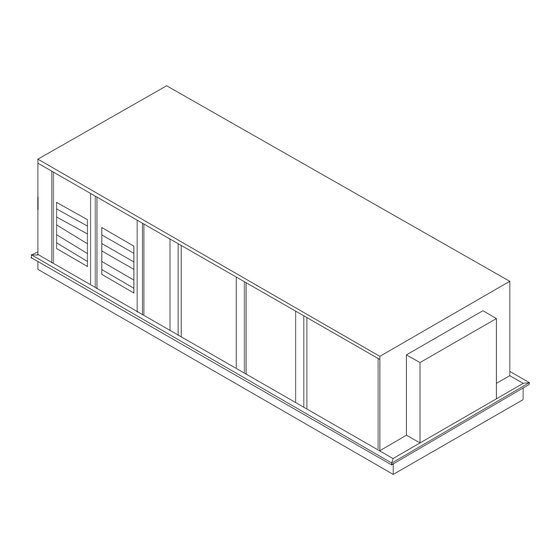
- Page 15 General Information Figure 1. Unit component layout and “ship with” locations RT-SVX35H-EN...
-
Page 16: Unit Inspection
"Starting the Unit". • Verify that the nameplate data matches the data on the Trane will not assume any responsibility for equipment sales order and bill of lading (including electrical data). damage resulting from condensate accumulation on the unit's electrical and/or mechanical components. - Page 17 Installation Figure 2. Typical control module location RT-SVX35H-EN...
- Page 18 Installation Figure 3. Typical W_HE casings 2 through 9 clearances for single or multiple unit installation Legend A = Return Air Opening B = Fresh Air Intake C = Supply Air Opening E = Optional 2’10−3/4” Access Door (180° swing) F = Hinged 2’10−3/4”...
- Page 19 Installation Dimensions (Note) Casing Furnace Size/MBH Length Height Low = 235 195-5/32 "9-5/32" 20 & 25 Ton High = 500 195-5/32 "9-5/32" Note: The length dimension is from the exhaust end of the unit. The height dimension is from the bottom of the unit base rail. Figure 4.
- Page 20 Installation Dimensions Furnace Size/ Casing 3 Length Height Low = 350 195-5/32” 9-5/32” 30 Ton High = 500 195-5/32” 9-5/32” (a) The length dimension is from the exhaust end of the unit. The height dimension is from the bottom of the unit base rail. Figure 5.
- Page 21 Installation Dimensions Furnace Size/ Casing 4 Length Height Low = 350 240-1/8" 9-5/32" 40 Ton High = 850 231-1/8" 9-5/32" (a) The length dimension is from the exhaust end of the unit. The height dimension is from the bottom of the unit base rail. Figure 6.
- Page 22 Installation Dimensions Furnace Size/ Casing 5 Length Height Low = 500 240-1/8" 9-5/32" 50 Ton High = 850 231-1/8" 9-5/32" (a) The length dimension is from the exhaust end of the unit. The height dimension is from the bottom of the unit base rail. Figure 7.
- Page 23 Installation Dimensions Furnace Size/ Casing 6 Length Height Low = 500 240-1/8" 9-5/32" 60-75 Ton High = 850 231-1/8" 9-5/32" (a) The length dimension is from the exhaust end of the unit. The height dimension is from the bottom of the unit base rail. Figure 8.
- Page 24 Installation Dimensions Furnace Size/ Casing 9 Length Height 90-130 Ton 1000 267-3/16" 10-11/32" (a) The length dimension is from the exhaust end of the unit. The height dimension is from the bottom of the unit base rail. Figure 9. W_HE casing 9 (90-130 ton) RT-SVX35H-EN...
- Page 25 Installation Table 4. W_HE center-of-gravity data Units with 100% Exhaust Fan 2 Row 4 Row 6 Row 8 Row Std. DX Coil Chilled Water Chilled Water Chilled Water Chilled Water Unit Casing Model Size 10’ 4” 3’ 4” 10’ 4” 3’...
- Page 26 Installation Table 4. (continued) W_HE center-of-gravity data Units with Supply and Exhaust Fan (VFD) 2 Row 4 Row 6 Row 8 Row Std. DX Coil Chilled Water Chilled Water Chilled Water Chilled Water Unit Casing Model Size 9’ 7” 3’ 4” 9’...
-
Page 27: Roof Curb And Ductwork
Trane's Engineering Bulletin RT-PRB022-EN provides Step-by-step curb assembly and installation instructions additional information concerning duct design and sound ship with each Trane accessory roof curb kit. Refer to the reduction. applicable sections in the current edition of RT-SVN14*-EN for W_HE casings 2 through 9. Follow the instructions... -
Page 28: Unit Rigging & Placement
Due to the accessibility of the electrical entrance, the pitch pocket can be installed after the unit is placed on the curb. If a Trane Curb Accessory Kit is not used: • The ductwork can be attached directly to the factory- provided flanges around the unit’s supply and return... - Page 29 Installation Figure 10. Unit rigging Figure 11. Typical unit base & roof curb cross section RT-SVX35H-EN...
-
Page 30: General Unit Requirements
Check the unit for shipping damage and material wiring poses FIRE and ELECTROCUTION hazards. To shortage; file a freight claim and notify Trane office. avoid these hazards, you MUST follow requirements for field wiring installation and grounding as described in •... -
Page 31: Requirements For Hot Water Heat (Wlhe)
Installation Requirements for Hot Water Heat (WLHE) in the filter section, and the other end routed to a suitable sensing location within the controlled space. • Route properly sized water piping through the base of Condensate Drain Connection the unit into the heating section. •... -
Page 32: Shipping Fasteners
Installation Shipping Fasteners 1. Remove and discard the shipping bolts from the fan assembly rails. Removing Supply and Exhaust Fan Shipping 2. Elevate the fan-and-motor assembly and slide the Channels (Motors >5Hp) shipping channels out from between the fan assembly rails and the unit's base rail. -
Page 33: O/A Sensor & Tubing Installation
Installation Figure 14. Removing fan assembly shipping hardware — W_HE casing 9 Note: Fan assemblies not equipped with rubber or spring isolators have mounting bolts at the same locations and must not be removed. O/A Sensor & Tubing Installation 3. Using the #10-32 x 1/2" screws provided, install the O/ A static pressure sensor vertically to the sensor An Outside Air Pressure Sensor is shipped with all units bracket. -
Page 34: Gas Heat Units (Wfhe)
Installation place, the gas supply line must be field-connected to the elbow located inside the gas heat control compartment. Figure 15. Outside air sensor & tubing WARNING Flammable Vapors! When connecting to existing gas lines be sure to shut off the gas supply ahead of connection point. To avoid explosion or possible fire, always purge all residual gas from piping before cutting into existing line or removing threaded fittings. - Page 35 Installation Note: Gas pressure in excess of 14" w.c. or 0.5 psig will damage the gas train. WARNING Failure to use a pressure regulating device will result in Hazard of Explosion! incorrect gas pressure. This can cause erratic operation due to gas pressure fluctuations as well as damage the gas Never use an open flame to detect gas leaks.
- Page 36 Installation Table 7. Modulating gas heat settings Natural Gas Full Modulation Partial Modulation Valve Actuator Air Damper Air Damper Actuator Voltage Actuator Voltage Left (Coarse) Right (Fine) Heater Size (MBH) Gas Orifice Range (VDC) Range (VDC) Setting Setting 7 - 10 7 - 9.7 6 - 10 6 - 8.7...
-
Page 37: Modulating
Installation Modulating Figure 17. 500 and 850 MBH - unit gas trains (natural gas) Figure 20. Modulating gas valve Pilot Shutoff Valve Pilot Shutoff Valve Burner Nozzle Burner Nozzle Pilot Solenoid Valve Pilot Solenoid Valve Pilot Regulator Valve Pilot Regulator Valve Pilot Shutoff Valve Pilot Shutoff Valve Figure 18. -
Page 38: Steam Heat Units (Wshe)
Installation 7. Install the 3-way valve in an upright position, piped for valve seating against the flow. Ensure that the valve’s Figure 21. Flu assembly location lends itself to serviceability. 8. The Type "W" hot water coil used in WLHE units is self- venting only when the tube water velocity exceeds 1.5 feet per second (fps). - Page 39 Installation Important: The valve actuators are not waterproof. 10. Steam trap selection should be based on the Failure to protect the valve from moisture maximum possible condensate flow and the may result in the loss of heating control. recommended load factors. 1.
- Page 40 Installation Figure 23. Hot water piping configuration for W_HE casing 9 Figure 24. Steam coil piping configuration for W_HE casings 2&3 RT-SVX35H-EN...
-
Page 41: Chilled Water Units
Installation Figure 25. Steam coil piping configuration for W_HE casings 4, 5, 6 and 9 Chilled Water Units without having to open the control panel door. The handle locations and its three positions are shown below; Chilled water coils are factory installed inside the cooling "ON"... -
Page 42: Electric Heat Units (Wehe)
Installation Figure 26. Disconnect switch external handle Note: All field installed wiring must conform to NEC guidelines as well as State and Local codes. WARNING Verify that the power supply available is compatible with Hazardous Voltage! the unit's nameplate ratings for all components. The available power supply must be within 10% of the rated Disconnect all electric power, including remote voltage stamped on the nameplate. - Page 43 Installation Main Unit Power Wiring WARNING Proper Field Wiring and Grounding Required! All field wiring MUST be performed by qualified personnel. Improperly installed and grounded field wiring poses FIRE and ELECTROCUTION hazards. To avoid these hazards, you MUST follow requirements for field wiring installation and grounding as described in NEC and your local/state electrical codes.
- Page 44 Installation Figure 27. Typical field power wiring for W_HE casings 2 through 6 RT-SVX35H-EN...
- Page 45 Installation Figure 28. Typical field power wiring for W_HE casings 9 Note: Refer to Figure 29, p. 46 for Customer Connection Wire Range notes. RT-SVX35H-EN...
- Page 46 Installation Figure 29. Customer connection wire range Table 11. Electrical service sizing data for W_HE casings 2 - 9 200/60/3, Nominal 230/60/3, Nominal 460/60/3, Nominal 575/60/3, Nominal Unit Component(s) (180-220V Utiliz.) (207-253V Utiliz.) (414-506V Utiliz.) (517-633V Utiliz.) Electric Heat (WEHE Only): FLA (1) FLA (1) FLA (1)
-
Page 47: Power Wire Sizing And Electrical Service Sizing Equations
Installation Select a fuse rating equal to the RDE value. If the RDE value does not equal a standard fuse size as listed in NEC 240 - Table 12. Electrical service sizing data — motors — 20- 130 tons 6, select the next higher standard fuse rating. Note: If the selected RDE is greater than the selected MOP Motor HP Supply/Exhaust/Return Fan Motor... - Page 48 Installation (cooling mode) values calculated using calculation #1 Figure 33, p. 57 illustrates the various control options with above. The second set of circuit values shown on the the required number of conductors for a Variable Air nameplate will be for the electric heating circuit as follows. Volume application.
-
Page 49: Constant Volume System Controls
Occupied\Unoccupied programming per day. Either one or all four periods can be programmed. If the power is Units equipped with a Trane Communication Interface interrupted, the program is retained in permanent (TCI), BACnet Communication Interface (BCI), or LonTalk memory. If power is off longer than 2 hours, only the clock communication Interface (LCI) option which utilizes a and day may have to be reset. - Page 50 This electronic analog sensor features single setpoint capability and timed override with override cancellation. It – Supply fan - OFF is used with a Trane Integrated Comfort™ system. Refer – VFD - 0% (if equipped) Table 15 for the Temperature vs. Resistance coefficient.
- Page 51 Installation 4. VOM Mode “D” Priority 4 - Purge: Occupied/Unoccupied output - Energized – Supply fan - ON VO Relay - Energized (with VOM module installed) – VFD - 100% (if equipped) OA Preheater State - Off (with VCM module installed) –...
- Page 52 Generic Building Automation System (1U51) 10.5 The Generic Building Automation System (GBAS) module 87.56 10.25 allows a non-Trane building control system to 74.65 communicate with the rooftop unit and accepts external 63.8 9.76 setpoints in form of analog inputs for cooling, heating, 54.66...
- Page 53 Installation Figure 30. Typical field wiring schematic for W_HE casings 2-9 CV control options. Refer to wiring notes, Figure 32, RT-SVX35H-EN...
- Page 54 Installation Figure 31. Typical ventilation override binary output wiring diagram for W_HE casings 2-9 CV control options. Refer to wiring notes, Figure 32, p. RT-SVX35H-EN...
- Page 55 Installation Figure 31. (continued from previous page) typical ventilation override binary output wiring diagram for W_HE casings 2-9 CV control options. Refer to wiring notes, Figure 32, p. RT-SVX35H-EN...
- Page 56 Installation Figure 32. Wiring notes for CV controls RT-SVX35H-EN...
- Page 57 Installation Figure 33. Typical ventilation override binary output wiring schematic for W_HE casings 2-9 VAV control options. Refer to wiring notes, Figure 35, p. RT-SVX35H-EN...
- Page 58 Installation Figure 34. Typical ventilation override binary output wiring diagram for W_HE casings 2-9 VAV control options. Refer to wiring notes, Figure 35, p. RT-SVX35H-EN...
- Page 59 Installation Figure 34. (continued from previous page) Typical ventilation override binary output wiring diagram for W_HE casings 2-9 VAV control options. Refer to wiring notes, Figure 35, p. RT-SVX35H-EN...
- Page 60 Installation Figure 35. Wiring notes - VAV RT-SVX35H-EN...
- Page 61 Installation Table 16. GBAS voltage vs. setpoint Unit Type Setpoint Input Voltage Setpoint Range Unoccupied Zone Cooling Setpoint 0.5 to 4.5 vdc 50°F to 90°F Occupied Zone Cooling Setpoint 0.5 to 4.5 vdc 50°F to 90°F Occupied Zone Heating Setpoint 0.5 to 4.5 vdc 50°F to 90°F S/A Cooling Setpoint...
- Page 62 Installation Figure 36. (continued from previous page) Typical GBAS analog input wiring schematic for W_HE casings 2 through 9 CV or VAV control options RT-SVX35H-EN...
- Page 63 Installation Table 17. GBAS Voltage vs. Setpoint Setpoint GBAS 0-5 VDC GBAS 0-10 VDC Valid Range Occ Zone Cooling Setpoint(CV only) 0.5 to 4.5 VDC 0.5 to 9.5 VDC 50 to 90°F Unocc Zone Cooling Setpoint 0.5 to 4.5 VDC 0.5 to 9.5 VDC 50 to 90°F Occ Zone Heating Setpoint(CV only)
-
Page 64: System Start-Up
System Start-up Cooling Sequence of Operation (IntelliPak airflow capacity. At Stage 1 of DX Cooling the minimum Fan Speed will be 37% and at Stage 2 of DX Controls Only) Cooling the Fan Speed will be at a minimum of 67%. Time delays are built into the controls to increase 2. -
Page 65: Gas Heating Sequence Of Operation
System Start-up Units equipped with 100% modulating closing "Stage 1" (K10 on SCM or K11 on MCM). After the first functional stage has started, the compressor module exhaust monitors the saturated refrigerant temperature and closes The exhaust dampers are controlled through an Exhaust/ the condenser fan output contact "1A", when the saturated Comparative Enthalpy Module (ECEM). -
Page 66: Modulating Gas Sequence Of Operation
System Start-up Modulating Gas Sequence of Operation On Variable Air Volume systems, the sequencing time delay relay (4DL6) will energize the combustion blower Full and Limited Modulating Gas Furnace motor relay (4K33) which switches the combustion blower motor to high speed and energizes the 2nd stage solenoid A typical electrical schematic for the modulating ignition on the gas valve (4L7) after approximately 60 seconds. - Page 67 System Start-up Flame Failure In the event that IC board 4U18 loses the “proof-of-flame” input signal during furnace operation, it will make one attempt at reignite. If a flame is not reestablished within the 10 second trial period, 4U18 will shut down and lock out the ignition /combustion control circuit.
- Page 68 System Start-up Figure 38. Typical fenwall ignition control system RT-SVX35H-EN...
- Page 69 System Start-up Figure 39. Typical Fenwall ignition control system RT-SVX35H-EN...
- Page 70 System Start-up Figure 40. Typical modulating gas heat schematic & connections diagram RT-SVX35H-EN...
- Page 71 System Start-up Figure 40. (continued from previous page) Typical modulating gas heat schematic & connections diagram RT-SVX35H-EN...
- Page 72 System Start-up Electric Heat Sequence of Operation Freeze Protection A typical electrical schematic for a 3-circuit, 70 kW electric A freezestat (4S12) is mounted inside the heat section of furnace control circuit appears in Figure 41, p. 73. As you WLHE and WSHE units to prevent the “wet”...
- Page 73 System Start-up Figure 41. Typical (3 Circuit) electric furnace schematic Use the checklist provided below in conjunction with the to complete all of the procedures described in this section “General Unit Requirement" checklist” to ensure that the before starting the unit for the first time. unit is properly installed and ready for operation.
-
Page 74: Voltage Supply And Voltage Imbalance
System Start-up WARNING WARNING Hazardous Voltage! Hazardous Voltage! Disconnect all electric power, including remote HIGH VOLTAGE IS PRESENT AT TERMINAL BLOCK 1TB1 disconnects before servicing. Follow proper lockout/ OR UNIT DISCONNECT SWITCH 1S14. Disconnect all tagout procedures to ensure the power can not be electric power, including remote disconnects before inadvertently energized. - Page 75 System Start-up Example: If the voltage readings of the supply power measured 221, 230, and 227, the average volts would be: 221 + 230 + 227 = 226 Avg. VD (reading farthest from average) = 221 The percentage of Imbalance equals: 100 X 226 - 221 = 2.2% The 2.2% imbalance in this example exceeds the maximum allowable imbalance of 2.0%.
-
Page 76: Verifying Proper Fan Rotation
System Start-up Verifying Proper Fan Rotation WARNING 1. Ensure that the "System" selection switch at the remote panel is in the "Off" position and the "Fan" Hazardous Voltage! selection switch for constant volume units is in the Disconnect all electric power, including remote "Auto"... -
Page 77: Variable Air Volume Systems
System Start-up a. Measure the actual fan rpm b. Calculate the Theoretical bhp WARNING i. Actual Motor Amps X Motor (hp) Hazardous Voltage! Motor Nameplate Amps HIGH VOLTAGE IS PRESENT AT TERMINAL BLOCK 1TB1 c. Plot this data onto the appropriate Fan Performance OR UNIT DISCONNECT SWITCH 1S14. -
Page 78: Exhaust Airflow Measurement
System Start-up 4. Open the Human Interface access door, located in the a. Drilling a small hole through the unit casing on each unit control panel, and press the SERVICE MODE key to side of the coil. Coil damage can occur if care is not display the first service screen. -
Page 79: Traq™ Sensor Airflow Measurement
System Start-up designate the delay before the test is to start. This service test will begin after the TEST START key is WARNING pressed and the delay designated in this step has Rotating Components! elapsed. Press the ENTER key to confirm this choice. During installation, testing, servicing and troubleshooting of this product it may be necessary to WARNING... - Page 80 System Start-up Figure 42. W_HE casing 2 supply fan performance curve 1700 RPM W_HE Casing 2 1600 RPM Dual 15 X 15 Fans 25 HP Entrance Losses - without Evap Coil 1500 RPM - without Filters 20 HP - without Return Air Dampers - without Exhaust Fan 1400 RPM Fan Curve Limits...
- Page 81 System Start-up Figure 44. W_HE casing 4 & 5 supply fan performance curve W_HE Casing 4 & 5 Dual 20 X 20 Fans Entrance Losses 40 HP - without Evap Coil 1200 RPM - without Filters - without Return Air Dampers - without Exhaust 30 HP 1100 RPM...
- Page 82 System Start-up Figure 46. W_HE casing 9 supply fan performance curve 10000 20000 30000 40000 50000 60000 Figure 47. Wet airside pressure drop at 0.075 lb/cu.ft. casing 2 - 9 standard evaporator coil Evaporator Wet Airside Pressure Drop at 0.075 lb/cu.ft. Casings 2-9 4000 6000 800010000 20000...
- Page 83 System Start-up Figure 48. Dry airside pressure drop at 0.075 lb/cu.ft. W_HE casings 2 - 9 standard evaporator coil Evaporator Dry Airside Pressure Drop at 0.075 lb/cu.ft. Casings 2-9 4000 6000 8000 10000 20000 40000 Unit Airflow, CFM RT-SVX35H-EN...
- Page 84 System Start-up Table 21. Component static pressure drops (in. W.G.) Evaporator Coil - R-410A Heating System Natural Gas Hot Water Steam Casing CFM Std Electric Size High All kWs High High 4-Row 4000 6000 8000 9000 10000 12000 5-Row 6000 9000 12000 14000...
- Page 85 System Start-up Table 21. Component static pressure drops (in. W.G.) Filters Econ.with Throwaway Cartridge or w/o Casing CFM Std Perm Wire Bag & & Std Roof Exhaust Size Std Fiber High Effic. Mesh Prefilter Prefilter Curb 4000 6000 8000 9000 10000 12000 1.19...
- Page 86 System Start-up Table 22. Supply air fan drive selections — casings 2-6 3 Hp 5 Hp 7½ Hp 10 Hp 15 Hp 20 Hp 25 Hp 30 Hp 40 Hp 50 Hp Casing Drive Drive Drive Drive Drive Drive Drive Drive Drive Drive...
- Page 87 System Start-up Table 24. W_HE casings 2-6 100% modulating exhaust fan performance Negative Static Pressure 0.250 0.500 0.750 1.000 1.2500 1.500 1.750 2.000 Casing Std. Size 4000 0.34 0.70 1.12 1.59 2.10 2.64 6000 0.61 1.03 1.52 2.07 2.66 8000 1.10 1.56 2.11...
- Page 88 System Start-up Table 26. 100% exhaust fan drive selections — casings 2 to 6 3 Hp 5 Hp 7½ Hp 10 Hp 15 Hp 20 Hp Casing Size Drive No Drive No Drive No Drive No Drive No Drive No 1000 1000 1100...
- Page 89 System Start-up Table 28. W_HE casings 2-6 50% modulating exhaust fan performance Negative Static Pressure 0.200 0.400 0.600 0.800 1.000 1.200 1.400 Casing Std. Size 2000 0.14 0.27 0.43 0.60 0.79 1.00 1.21 3000 0.27 0.42 0.61 0.81 1.03 1.27 1.51 4000 0.51...
-
Page 90: Economizer Damper Adjustment
System Start-up Table 30. 50% exhaust fan drive selections (casings 2-9) 3 HP 5 HP 7½ HP 15 HP Casing Size Drive No Drive No Drive No Drive No 1000 4 & 5 Economizer Damper Adjustment overload the supply fan motor and cause building pressurization control problems due to improper cfm Exhaust Air Dampers being delivered to the space. - Page 91 System Start-up 2. Close the disconnect switch or circuit protector switch 11. Remove the drive rod and swivel from the crank that provides the supply power to the unit's terminal arm(s). If only one hole requires changing, loosen only block 1TB1 or the unit mounted disconnect switch that end.
- Page 92 System Start-up Table 32. Fresh air damper pressure drop (inches w.c.) Casing 2 (20 and 25 Ton) Units Casing 5 (50 Ton) Units Damper Position Damper Position 4000 0.03 0.04 0.06 0.13 0.16 0.33 10000 0.03 0.04 0.09 0.18 0.23 0.55 6000 0.03...
-
Page 93: Thermostatic Expansion Valves
System Start-up Tables are based on outdoor ambient between 65°F & 105°F, relative humidity above 40 percent. Measuring the Figure 49. Fresh air & return air linkage adjustment operating pressures can be meaningless outside of these ranges. Top View Measuring Superheat 1. -
Page 94: Gas Furnace Start-Up
System Start-up Electric Heat • Supply Fan (On) WARNING • Variable Frequency Drive (100% Output, if Hazardous Gases and Flammable Vapors! applicable) Exposure to hazardous gases from fuel substances have • RTM Occ/Unocc Output (Unoccupied) been shown to cause cancer, birth defects or other •... - Page 95 System Start-up has a clearly defined shape, and is primarily (75%) blue Note: Do not adjust the combustion air damper while the in color with an orange tip. furnace is operating at low-fire. 5. Check the manifold gas pressure by using the manifold 4.
- Page 96 System Start-up Figure 51. Natural gas combustion curve (ratio of O to C0 in percent) Curve Fuel 1,000 BTU per cu. ft. of Natural Gas. 0 1 2 3 4 5 6 7 8 9 10 11 12 13 14 15 16 17 18 19 20 21 Percent Oxygen Figure 52.
-
Page 97: Heat Exchanger
System Start-up Full Modulating Gas Furnace 4. Once the system has started, check the appearance of the flame through the sight glass provided on the front Full Modulating gas heaters are available for the 500, 850 of the heat exchanger. In appearance, a normal flame and 1000 MBH heater sizes. -
Page 98: Limited Modulating Gas Furnace
System Start-up 13. Press the STOP key at the Human Interface Module in the unit control panel to stop the system operation. Figure 53. Modulating gas regulator Limited Modulating Gas Furnace Limited Modulating gas heaters are available for the 500, 850 and 1000 MBH heater sizes. - Page 99 System Start-up Final Unit Checkout Figure 54. Typical gas furnace damper assembly After completing all of the checkout and start-up procedures outlined in the previous sections (i.e., operating the unit in each of its modes through all available stages of cooling and heating), perform these final checks before leaving the unit: WARNING Hazardous Voltage!
-
Page 100: Service & Maintenance
Service & Maintenance Table 34. Control settings and time delays Control Description Elec. Designation Contacts Open Contacts Closed Combustion Airflow Switch 4S25 see Note 1 0.1 - 0.25" wc rise in press diff (Gas Heat Only) High Limit Cutout 4S26 250 + 15°F 210°F (Gas Heat Only) - Page 101 Service & Maintenance Figure 55. Unit internal fuse replacement data for air-cooled units RT-SVX35H-EN...
- Page 102 Service & Maintenance Table 35. Filter data Cartridge Filters Panel-Type Filters Bag-Type Filters (Box-Type) Panel-Type Prefilters Unit Model Size of each Qty. Size of each Qty.(b) Size of each Qty. Size of each 12 X 24 X 19 24 X 12 X 12 12 X 24 X 2 W_HE-Casing 2 20 X 20 X 2...
-
Page 103: Vfd Programming Parameters
OK button. replacing the drive. Should replacing the a VFD become necessary, the replacement is not configured with all of Trane's operating WARNING parameters. The VFD must be programmed before attempting to operate the unit. -
Page 104: Fan Belt Adjustment
Service & Maintenance (f) Use Up and Down Arrow buttons to select the worn. Units with dual belts require a matched set of belts specific parameter to ensure equal belt length. (g) Press OK When removing or installing the new belts, do not stretch them over the sheaves. - Page 105 Service & Maintenance 6. Recheck the tension of the new belts at least twice during the first 2 to 3 days of operation. Belt tension will decrease rapidly until the new belts are “run in”. Readjust the belt tension as necessary to correct for any stretching that may have occurred.
- Page 106 Service & Maintenance Figure 58. Typical power wiring schematic - power wires - standard - casing 2-9 - air handler with optional controls RT-SVX35H-EN...
- Page 107 Service & Maintenance Figure 58. (continued from previous page) Typical power wiring schematic - power wires - standard - casing 2-9 air handler with optional controls RT-SVX35H-EN...
- Page 108 Service & Maintenance Figure 59. Typical wiring schematic for air handler with DX coil, casing 2-9 RT-SVX35H-EN...
- Page 109 Service & Maintenance Figure 59. (continued from previous page) Typical wiring schematic for air handler with DX coil, casing 2-9 RT-SVX35H-EN...
- Page 110 Service & Maintenance Figure 60. Typical wiring schematic for air handler chilled water with or without preheat, casing 2-9 RT-SVX35H-EN...
- Page 111 Service & Maintenance Figure 60. (continued from previous page) Typical wiring schematic for air handler chilled water with or without preheat, casing 2-9 RT-SVX35H-EN...
-
Page 112: Monthly Maintenance
Service & Maintenance Monthly Maintenance Figure 61. Typical RTM wiring schematic for casing 2 - 9 Before completing the following checks, turn the unit OFF and lock the main power disconnect switch open. RT-SVX35H-EN... - Page 113 Service & Maintenance • Generally inspect the unit for unusual conditions (e.g., loose access panels, leaking piping connections, etc.) WARNING • Make sure that all retaining screws are reinstalled in Hazardous Voltage! the unit access panels once these checks are complete. Disconnect all electric power, including remote Heating Season disconnects before servicing.
- Page 114 8.5), add an inhibitor (contact your local Trane Parts Center for appropriate detergents). Spray the 2. Remove enough panels and components from the unit detergent on the complete surface of the coil, let stand for to gain sufficient access to the coil.
-
Page 115: Wiring Matrix
Wiring Matrix Note: Wiring diagrams can be accessed via e-Library by entering the diagram number in the literature order number search field or by calling technical support. Diagram Number Description 2308-6115 Connection, Control Box - w/Supply VFD Air Handler 2308-6116 Connection, Control Box - w/Exh/Rtn VFD Air Handler 2308-6117 Connection, Control Box - w/Sup &... -
Page 116: Warranty And Liability Clause
Commercial Equipment Rated 20 Tons and Larger and Related Accessories PRODUCTS COVERED - This warranty* is extended by NOTICE: Trane and applies only to commercial equipment rated 20 Tons and larger and related accessories. Equipment Damage From Ultraviolet (UV) The Company warrants for a period of 12 months from... -
Page 117: Index
Index Symbols 4K33 65 auxiliary switch 66 4K34 72 "System" selection switch 76 4K35 72 “Ship with” Locations 15 BACnet 9 4K36 72 Numerics Bag-Type Filters 101 4K37 72 BAYSENS016 50 115 volt control relay 66 4K38 72 BAYSENS021 50 1CB1 11 4K39 72 BAYSENS073 50... - Page 118 Index CO2 Reset Start Value 65 Outputs) 49 electrical entrance 27 CO2 sensor 65 Cooling Season 112 Electrical Phasing 74 Coil Cleaning 112 Cooling Sequence 14 Electrical Service Sizing Equations 42 coil maintenance 113 Cooling Sequence of Operation 64 Electrical Sizing Data (Casings 2- combustion air actuator 66 corrosion 112 9) 46...
- Page 119 Index Flame Failure 67 Gas Valve Adjustment Screw Human Interface Module 9 Locations 95 flame rod 66 gasket 112 Hydronic Heat Actuator 12 flame sensing rod 65 gaskets 112 Float-and-Thermostatic (FT) trap 39 gauge plunger 103 flue assembly 37 IC board 66 GBAS 63 Flue Assembly Installation 37 ignition control board 65...
- Page 120 Index main steam valve 93 Occupied Heating - Supply Air Removing Fan Assembly Shipping Temperature 12 Hardware (Casing 2-6) 32 main supply power entry 27 Occupied Heating Operation 13 Removing Fan Assembly Shipping Main Unit Power Wiring 43 Hardware (Casing 9) 33 Occupied/Unoccupied Contacts manifold gas pressure 93 Requirements for Electric Heat...
- Page 121 98 Steam heating coils 38 Module 9 Unit Nameplate Locations 7 Steam or Hot Water Coils 113 Trane Curb Accessory Kit 28 Unit Power Terminal 74 Steam or Hot Water Heat 93 Trane ICS™ 9 Unit Record Information 3 steam trap connection 39 Trane Tracer Summit™...
- Page 122 Index Voltage Supply 74 Voltage Supply and Voltage Imbalance 74 VOM - Optional 1U51 9 VOM Contacts 50 W_HE Center-of-Gravity Data 25 water carryover 113 WEHE Units w/200V or 230V Electric Heat 30 Weight Information 16 Wet Heat 72 Wet heat actuator 72 Wet Heat Coil Fin Data 101 Wet Heat Sequence of Operation 72 wet heat system 38...
- Page 123 For more information, please visit trane.com or tranetechnologies.com. Trane has a policy of continuous product and product data improvement and reserves the right to change design and specifications without notice. We are committed to using environmentally conscious print practices.
Need help?
Do you have a question about the IntelliPak WEHE Series and is the answer not in the manual?
Questions and answers