Advertisement
Table of Contents
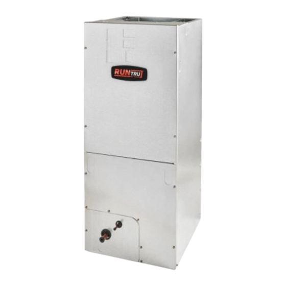
Installer's Guide
Convertible Air Handlers
1–1/2 — 5 Ton
A4AH4E24A1B60A
A4AH4E30A1B30A
A4AH4E36A1C30A
A4AH4E42B1C30A
A4AH4E48B1C30A
A4AH4E60B1C30A
Only qualified personnel should install and service the equipment. The installation, starting up, and servicing of heating, ventilating, and air-conditioning
equipment can be hazardous and requires specific knowledge and training. Improperly installed, adjusted or altered equipment by an unqualified person
could result in death or serious injury. When working on the equipment, observe all precautions in the literature and on the tags, stickers, and labels that
are attached to the equipment.
July 2022
The A4AH4 series air handler is designed for installation in a closet,
utility room, alcove, basement, crawlspace or attic. These versatile
units are applicable to air conditioning and heat pump
applications. Several models are available to meet the specific
requirements of the outdoor equipment. Field installed electric
resistance heaters are available.
S S A A F F E E T T Y Y W W A A R R N N I I N N G G
1 1 8 8 - - G G F F 1 1 6 6 D D 1 1 - - 1 1 A A - - E E N N
Advertisement
Table of Contents


Need help?
Do you have a question about the A4AH4E24A1B60A and is the answer not in the manual?
Questions and answers
What size filter do we need? The previous owner cut one to size…