Advertisement
Installer's Guide
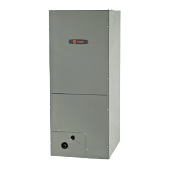
Convertible Air Handlers
1–1/2 — 5 Ton
TEM4B0B24M21SA
TEM4A0B31M31SB
TEM4A0C42S41SC
TEM4B0C37M31SA
TEM4A0C43M41SB
TEM4A0C48S41SC
TEM4A0C49M41SB
TEM4B0C60S51SA
Only qualified personnel should install and service the equipment. The installation, starting up, and servicing of heating, ventilating, and air-conditioning
equipment can be hazardous and requires specific knowledge and training. Improperly installed, adjusted or altered equipment by an unqualified person
could result in death or serious injury. When working on the equipment, observe all precautions in the literature and on the tags, stickers, and labels that
are attached to the equipment.
July 2023
The TEM4 series air handler is designed for installation in a closet, utility
room, alcove, basement, crawlspace or attic. These versatile units are
applicable to air conditioning and heat pump applications. Several models
are available to meet the specific requirements of the outdoor equipment.
Field installed electric resistance heaters are available.
S S A A F F E E T T Y Y W W A A R R N N I I N N G G
1 1 8 8 - - G G F F 7 7 5 5 D D 1 1 - - 1 1 C C - - E E N N
Advertisement

Subscribe to Our Youtube Channel
Related Manuals for Trane TEM4 Series


Summary of Contents for Trane TEM4 Series
- Page 1 TEM4A0C48S41SC TEM4A0C49M41SB TEM4B0C60S51SA The TEM4 series air handler is designed for installation in a closet, utility room, alcove, basement, crawlspace or attic. These versatile units are applicable to air conditioning and heat pump applications. Several models are available to meet the specific requirements of the outdoor equipment.
- Page 2 SAFETY SECTION I I m m p p o o r r t t a a n n t t : : This document contains a wiring diagram, W W A A R R N N I I N N G G a parts list, and service information.
- Page 3 S S A A F F E E T T Y Y S S E E C C T T I I O O N N Features W W A A R R N N I I N N G G Table 1.
-
Page 4: Table Of Contents
Table of Contents Installation Instructions..... 5 Outline Drawing ......15 Field Wiring and Electrical Data. -
Page 5: Installation Instructions
Installation Instructions 1. U U n n p p a a c c k k i i n n g g and piped in accordance with applicable building codes. Carefully unpack the unit and inspect the contents for damage. If any damage is found at the time of The figure shows the operation of a properly delivery, proper notification and claims should be designed trap under normal operating conditions... - Page 6 I I n n s s t t a a l l l l a a t t i i o o n n I I n n s s t t r r u u c c t t i i o o n n s s Vent must be 75 degree C (167 degree F) minimum -This vent pipe MUST...
- Page 7 I I n n s s t t a a l l l l a a t t i i o o n n I I n n s s t t r r u u c c t t i i o o n n s s Circuit R to O energizes the reversing valve to the D D e e f f r r o o s s t t cooling position.
-
Page 8: Field Wiring And Electrical Data
Field Wiring and Electrical Data Figure 1. Field Wiring Diagrams AC SYSTEMS HEAT PUMP SYSTEMS Outdoor Outdoor Thermostat Air Handler Thermostat Air Handler Unit Unit 24 VAC HOT 24 VAC HOT 24 VAC 24 VAC Common Common Blue Blue COOL/HEAT COOLING 1st STAGE HEAT... -
Page 9: Performance And Electrical Data
Performance and Electrical Data Table 3. Air Flow Performance Tables TEM4B0B24M21SA AIRFLOW EXTERNAL STATIC (in w.g) Speed Taps: 208 – 230 VOLTS High Med-High Med † 1140 1078 1087 1017 1034 • Low = Taps 1–2, Med = Tap 3, Med-High= Tap 4, High = Tap 5 TEM4A0B31M31SB AIRFLOW EXTERNAL STATIC... - Page 10 P P e e r r f f o o r r m m a a n n c c e e a a n n d d E E l l e e c c t t r r i i c c a a l l D D a a t t a a TEM4B0C37M31SA, TEM4A0C43M41SB AIRFLOW EXTERNAL STATIC...
- Page 11 P P e e r r f f o o r r m m a a n n c c e e a a n n d d E E l l e e c c t t r r i i c c a a l l D D a a t t a a Table 4.
- Page 12 P P e e r r f f o o r r m m a a n n c c e e a a n n d d E E l l e e c c t t r r i i c c a a l l D D a a t t a a TEM4A0C42S41SC BAYHTR1517BRK with single circuit power...
- Page 13 P P e e r r f f o o r r m m a a n n c c e e a a n n d d E E l l e e c c t t r r i i c c a a l l D D a a t t a a TEM4A0C48S41SC BAYHTR1525BRK- 20500...
-
Page 14: Minimum Airflow Cfm
Minimum Airflow CFM TEM4B0B24M21SA Heater Minimum Heat Speed Tap With Heat Pump Without Heat Pump BAYHTR1504BRK, BAYHTR1504LUG, BAYHTR1505BRK, BAYHTR1505LUG BAYHTR1508BRK, BAYHTR1508LUG, BAYHTR1510BRK, BAYHTR1510LUG, BAYHTR3510LUG High TEM4A0B31M31SB Minimum Heat Speed Tap Heater With Heat Pump Without Heat Pump BAYHTR1504BRK, BAYHTR1504LUG, BAYHTR1505BRK, BAYHTR1505LUG BAYHTR1508BRK, BAYHTR1508LUG, BAYHTR1510BRK, BAYHTR1510LUG Med-High Med-Low... -
Page 15: Outline Drawing
Outline Drawing NOTE: THIS UNIT IS APPROVED FOR INSTALLATION CLEARANCES TO COMBUSTIBLE MATERIAL AS STATED ON THE UNIT RATING NAMEPLATE PRODUCT DIMENSIONS Flow Gas Line Air Handler Model Control Braze TEM4B0B24 45.02 18.50 16.50 16.75 4.68 7.33 18.34 TEM4A0B31 46.77 18.50 16.50 16.75... -
Page 16: Heater Pressure Drop Table
Heater Pressure Drop Table Number of Racks Heater Racks Airflow Heater Model No. of Racks Air Pressure Drop — Inches W.G. BAYHTR1504 1800 0.02 0.04 0.06 0.14 BAYHTR1505 1700 0.02 0.04 0.06 0.14 BAYHTR1508 1600 0.02 0.04 0.06 0.13 BAYHTR1510 1500 0.02 0.04... -
Page 17: Coil Conversion Instructions
Coil Conversion Instructions D D o o w w n n f f l l o o w w 5. On both sides of the cabinet, remove the screws that hold the coil support brackets and retain for I I m m p p o o r r t t a a n n t t : : Restrictions apply to Downflow later use. - Page 18 C C o o i i l l C C o o n n v v e e r r s s i i o o n n I I n n s s t t r r u u c c t t i i o o n n s s 14.
- Page 19 C C o o i i l l C C o o n n v v e e r r s s i i o o n n I I n n s s t t r r u u c c t t i i o o n n s s Figure 8.
- Page 20 C C o o i i l l C C o o n n v v e e r r s s i i o o n n I I n n s s t t r r u u c c t t i i o o n n s s Figure 10.
- Page 21 C C o o i i l l C C o o n n v v e e r r s s i i o o n n I I n n s s t t r r u u c c t t i i o o n n s s Figure 12.
- Page 22 C C o o i i l l C C o o n n v v e e r r s s i i o o n n I I n n s s t t r r u u c c t t i i o o n n s s Figure 14.
- Page 23 C C o o i i l l C C o o n n v v e e r r s s i i o o n n I I n n s s t t r r u u c c t t i i o o n n s s I I m m p p o o r r t t a a n n t t : : Make sure that the coil corner locks in place Figure 17.
-
Page 24: Checkout Procedures
About Trane and American Standard Heating and Air Conditioning Trane and American Standard create comfortable, energy efficient indoor environments for residential applications. For more information, please visit www.trane.com or www.americanstandardair.com. The manufacturer has a policy of continuous data improvement and it reserves the right to change design and specifications without notice. We are committed to using environmentally conscious print practices.
Need help?
Do you have a question about the TEM4 Series and is the answer not in the manual?
Questions and answers
Does this unit have AUX heat?
Yes, the Trane TEM4 Series unit supports field-installed electric resistance heaters, which can provide auxiliary heat.
This answer is automatically generated