Table of Contents
Advertisement
Quick Links
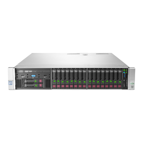
HPE ProLiant DL560 Gen9 Server
Maintenance and Service Guide
Abstract
This guide describes identification and maintenance procedures, diagnostic tools, specifications, and requirements for hardware
components and software. This guide is for an experienced service technician. Hewlett Packard Enterprise assumes you are qualified in the
servicing of computer equipment, trained in recognizing hazards in products, and are familiar with weight and stability precautions.
Part Number: 796439-003
June 2020
Edition: 3
Advertisement
Table of Contents

Related Manuals for HPE ProLiant DL560 Gen9


Summary of Contents for HPE ProLiant DL560 Gen9
- Page 1 HPE ProLiant DL560 Gen9 Server Maintenance and Service Guide Abstract This guide describes identification and maintenance procedures, diagnostic tools, specifications, and requirements for hardware components and software. This guide is for an experienced service technician. Hewlett Packard Enterprise assumes you are qualified in the servicing of computer equipment, trained in recognizing hazards in products, and are familiar with weight and stability precautions.
- Page 2 © Copyright 2015, 2020 Hewlett Packard Enterprise Development LP The information contained herein is subject to change without notice. The only warranties for Hewlett Packard Enterprise products and services are set forth in the express warranty statements accompanying such products and services. Nothing herein should be construed as constituting an additional warranty.
-
Page 3: Table Of Contents
SAS expander card option ............................. 61 AROC controller ..............................66 Power supply backplane ............................67 DIMMs ..................................68 HPE Smart Storage Battery ........................... 69 Heatsink ................................. 70 Processor ................................72 Power supply blank ..............................76 ... - Page 4 Mechanical specifications ............................. 108 Power supply specifications ..........................108 HPE 1500 W Common Slot Platinum Plus Hot-Plug Power Supply (94% efficiency) ....... 109 HPE 1200 W Common Slot Platinum Plus Hot-Plug Power Supply (94% efficiency) ....... 109 ...
-
Page 5: Customer Self Repair
For more information about the Hewlett Packard Enterprise CSR program, contact your local service provider. For the North American program, go to the Hewlett Packard Enterprise CSR website (http://www.hpe.com/support/selfrepair). Parts only warranty service Your Hewlett Packard Enterprise Limited Warranty may include a parts only warranty service. Under the terms of parts only warranty service, Hewlett Packard Enterprise will provide replacement parts free of charge. - Page 6 Pour plus d'informations sur le programme CSR de Hewlett Packard Enterprise, contactez votre Mainteneur Agrée local. Pour plus d'informations sur ce programme en Amérique du Nord, consultez le site Web Hewlett Packard Enterprise (http://www.hpe.com/support/selfrepair). Service de garantie "pièces seules" Votre garantie limitée Hewlett Packard Enterprise peut inclure un service de garantie "pièces seules".
- Page 7 Per ulteriori informazioni sul programma CSR di Hewlett Packard Enterprise, contattare il centro di assistenza di zona. Per il programma in Nord America fare riferimento al sito Web (http://www.hpe.com/support/selfrepair). Servizio di garanzia per i soli componenti La garanzia limitata Hewlett Packard Enterprise può includere un servizio di garanzia per i soli componenti.
- Page 8 Weitere Informationen über das Hewlett Packard Enterprise Customer Self Repair Programm erhalten Sie von Ihrem Servicepartner vor Ort. Informationen über das CSR-Programm in Nordamerika finden Sie auf der Hewlett Packard Enterprise Website unter (http://www.hpe.com/support/selfrepair). Parts-only Warranty Service (Garantieservice ausschließlich für Teile) Ihre Hewlett Packard Enterprise Garantie umfasst möglicherweise einen Parts-only Warranty Service...
- Page 9 Packard Enterprise, póngase en contacto con su proveedor de servicios local. Si está interesado en el programa para Norteamérica, visite la página web de Hewlett Packard Enterprise CSR (http://www.hpe.com/support/selfrepair). Servicio de garantía exclusivo de componentes La garantía limitada de Hewlett Packard Enterprise puede que incluya un servicio de garantía exclusivo de componentes.
- Page 10 Neem contact op met een Service Partner voor meer informatie over het Customer Self Repair programma van Hewlett Packard Enterprise. Informatie over Service Partners vindt u op de Hewlett Packard Enterprise website (http://www.hpe.com/support/selfrepair). Garantieservice "Parts Only" Het is mogelijk dat de Hewlett Packard Enterprise garantie alleen de garantieservice "Parts Only" omvat.
- Page 11 Para obter mais informações sobre o programa de reparo feito pelo cliente da Hewlett Packard Enterprise, entre em contato com o fornecedor de serviços local. Para o programa norte-americano, visite o site da Hewlett Packard Enterprise (http://www.hpe.com/support/selfrepair). Serviço de garantia apenas para peças A garantia limitada da Hewlett Packard Enterprise pode incluir um serviço de garantia apenas para...
- Page 12 Customer self repair 12...
- Page 13 Customer self repair 13...
- Page 14 Customer self repair 14...
-
Page 15: Illustrated Parts Catalog
Illustrated parts catalog Mechanical components Hewlett Packard Enterprise continually improves and changes product parts. For complete and current supported parts information, see the Hewlett Packard Enterprise PartSurfer website (http://www.hpe.com/info/partssurfer). Item Description Spare part number Customer self repair (on page 5) - Page 16 Item Description Spare part number Customer self repair (on page 5) c) Secondary PCI blank cover — — d) Fan blank (2) — — e) Smart Array Controller blank — — Rail kit* — — a) LFF 2U easy install rail kit 744115-001 Mandatory b) Cable management arm...
- Page 17 Obligatorio—Componentes cuya reparación por parte del usuario es obligatoria. Si solicita a Hewlett Packard Enterprise que realice la sustitución de estos componentes, tendrá que hacerse cargo de los gastos de desplazamiento y de mano de obra de dicho servicio. Opcional—Componentes cuya reparación por parte del usuario es opcional. Estos componentes también están diseñados para que puedan ser reparados por el usuario.
-
Page 18: System Components
System components Hewlett Packard Enterprise continually improves and changes product parts. For complete and current supported parts information, see the Hewlett Packard Enterprise PartSurfer website (http://www.hpe.com/info/partssurfer). Item Description Spare part Customer self repair number (on page 5) Processors — —... - Page 19 Power supply, hot-plug 1500 W -48 VDC 794734-001 Mandatory Common Slot* FlexibleLOM — — a) HPE 1GbE 4-port, 331FLR Adapter FIO Kit 634025-001 Mandatory b) HPE 10GbE 2-port, 530FLR Adapter FIO Kit* 649869-001 Mandatory c) HPE Flexfabric 10Gb 2-port, 554FLR-SFP+...
- Page 20 Item Description Spare part Customer self repair number (on page 5) d) 16 GB, 2Rx4, PC4-2133L* 774173-001 Mandatory e) 32 GB, 4Rx4, PC4-2133L* 774174-001 Mandatory DIMMs designed for Intel Xeon E5-4600 v4 — — processors a) 8 GB, PC4-2400R, 1Gx72 819410-001 Mandatory b) 16 GB, PC4-2400T-R, 2Gx72...
- Page 21 Item Description Spare part Customer self repair number (on page 5) y) 800 GB 12G SAS SFF, ME, SC, EM, SSD* 741228-001 Mandatory z) 300 GB 6G SAS 10K SFF, SC, HDD* 653955-001 Mandatory aa) 450 GB 6G SAS 10K SFF, SC, HDD* 653956-001 Mandatory bb) 600 GB 6G SAS 10K SFF, SC, HDD*...
- Page 22 Mandatory *Not shown **All processors in this HPE ProLiant server must have the same cache size, speed, number of cores, and rated maximum power consumption. Mandatory—Parts for which customer self repair is mandatory. If you request Hewlett Packard Enterprise to replace these parts, you will be charged for the travel and labor costs of this service.
- Page 23 Packard Enterprise per la sostituzione, potrebbero essere addebitate spese aggiuntive a seconda del tipo di garanzia in assistenza previsto per il prodotto. No—Alcune parti Hewlett Packard Enterprise non sono progettate la riparazione in autonomia da parte del cliente. In base a quanto previsto dalla garanzia per il cliente, Hewlett Packard Enterprise richiede l'intervento di un tecnico autorizzato per la sostituzione della parte.
- Page 24 Illustrated parts catalog 24...
-
Page 25: Removal And Replacement Procedures
Removal and replacement procedures Required tools You need the following items for some procedures: T-10/T-15 Torx screwdriver HPE Insight Diagnostics software ("HPE Insight Diagnostics" on page 91) Safety considerations Before performing service procedures, review all the safety information. Preventing electrostatic discharge To prevent damaging the system, be aware of the precautions you need to follow when setting up the system or handling parts. -
Page 26: Server Warnings And Cautions
This symbol indicates the presence of a hot surface or hot component. If this surface is contacted, the potential for injury exists. WARNING: To reduce the risk of injury from a hot component, allow the surface to cool before touching. This symbol indicates that the component exceeds the recommended weight for one individual to handle safely. -
Page 27: Extend The Server From The Rack
If the rack environment, cabling configuration, or the server location in the rack creates awkward conditions, remove the server from the rack. Access the product rear panel (on page 30). Access the Systems Insight Display ("Access the Systems Insight Display option"... -
Page 28: Power Down The Server
OS. If an application stops responding, you can use this method to force a shutdown. Use a virtual power button selection through HPE iLO. This method initiates a controlled remote shutdown of applications and the OS before the server enters standby mode. - Page 29 This symbol indicates that the component exceeds the recommended weight for one individual to handle safely. WARNING: To reduce the risk of personal injury or damage to the equipment, 27.66 kg observe local occupational health and safety requirements and guidelines for manual 61.00 lb material handling.
-
Page 30: Access The Product Rear Panel
Access the product rear panel Opening the cable management arm To access the server rear panel: Release the cable management arm. Open the cable management arm. The cable management arm can be right-mounted or left-mounted. Access the Systems Insight Display option Press and release the panel. -
Page 31: Access Panel
After the display fully ejects, rotate the display sideways to view the LEDs. Access panel WARNING: To reduce the risk of personal injury from hot surfaces, allow the drives and the internal system components to cool before touching them. WARNING: To reduce the risk of personal injury, electric shock, or damage to the equipment, remove the power cord to remove power from the server. -
Page 32: Air Baffle
Air baffle WARNING: To reduce the risk of personal injury, electric shock, or damage to the equipment, remove the power cord to remove power from the server. The front panel Power On/Standby button does not completely shut off system power. Portions of the power supply and some internal circuitry remain active until AC power is removed. -
Page 33: Mezzanine Tray Option
Mezzanine tray option Power down the server (on page 28). Remove all power: Disconnect each power cord from the power source. Disconnect each power cord from the server. Extend the server from the rack (on page 27). Remove the access panel ("Access panel"... -
Page 34: Pcie Riser Board
Remove the riser cage. To replace the component, reverse the removal procedure. PCIe riser board WARNING: To reduce the risk of personal injury, electric shock, or damage to the equipment, remove the power cord to remove power from the server. The front panel Power On/Standby button does not completely shut off system power. -
Page 35: Remove The Secondary Pci Riser Cage
Remove the PCIe riser board. To replace the component, reverse the removal procedure. Remove the secondary PCI riser cage Power down the server (on page 28). Remove all power: Disconnect each power cord from the power source. Disconnect each power cord from the server. Extend the server from the rack (on page 27). -
Page 36: Systems Insight Display
Systems Insight Display Power down the server (on page 28). Remove all power: Disconnect each power cord from the power source. Disconnect each power cord from the server. Extend the server from the rack (on page 27). Remove the access panel ("Access panel"... - Page 37 To replace the component: Route the cable through the opening in the front of the server, and then install the SID power switch module. Secure the module using the existing T-10 screw. Using the cable trough, connect the SID module cable to the front panel connector and to the power switch module connector.
-
Page 38: Hot-Plug Fan
The server shuts down in the following temperature-related scenarios: At POST and in the OS, HPE iLO performs an orderly shutdown if a cautionary temperature level is detected. If the server hardware detects a critical temperature level before an orderly shutdown occurs, the server performs an immediate shutdown. -
Page 39: Fan Cage
Remove the hot-plug fan. CAUTION: Do not operate the server for long periods with the access panel open or removed. Operating the server in this manner results in improper airflow and improper cooling that can lead to thermal damage. To replace the component, reverse the removal procedure. Fan cage WARNING: To reduce the risk of personal injury, electric shock, or damage to the equipment, remove the power cord to remove power from the server. -
Page 40: Drive Blank
Remove the fan cage. To replace the component, reverse the removal procedure. Drive blank CAUTION: To prevent improper cooling and thermal damage, do not operate the server unless all bays are populated with either a component or a blank. To remove the component: To replace the component, slide the component into the bay until it clicks. -
Page 41: 8Sff Front Drive Cage
Remove the drive. To replace the component, reverse the removal procedure. 8SFF front drive cage Power down the server (on page 28). Remove all power: Disconnect each power cord from the power source. Disconnect each power cord from the server. Extend the server from the rack (on page 27). -
Page 42: Drive Cage Backplane
Bay 1 Bay 2 To replace the component, reverse the removal procedure. Drive cage backplane Power down the server (on page 28). Remove all power: Disconnect each power cord from the power source. Disconnect each power cord from the server. Extend the server from the rack (on page 27). -
Page 43: 2Sff Drive Cage Backplane
Remove the air baffle ("Air baffle" on page 32). Remove the mezzanine tray ("Mezzanine tray option" on page 33). Disconnect all cables, and then remove the backplane. To replace the component, reverse the removal procedure. 2SFF drive cage backplane Power down the server (on page 28). Remove all power: Disconnect each power cord from the power source. -
Page 44: Universal Media Bay
Disconnect all cables, and then remove the backplane. To replace the component, reverse the removal procedure. Universal media bay Power down the server (on page 28). Remove all power: Disconnect each power cord from the power source. Disconnect each power cord from the server. Extend the server from the rack (on page 27). - Page 45 Disconnect the USB/VGA cables through the universal media bay opening, and then remove the universal media bay. To replace the component: Route the USB/VGA cables through the universal media bay opening, and then install the universal media bay. Removal and replacement procedures 45...
-
Page 46: Universal Media Bay With Two-Bay Sff Drive Cage
Using the cable trough, connect the cable to the front VGA/USB 2.0 connector on the system board. Depending on the server options installed, do one of the following: Install the air baffle ("Air baffle" on page 32). Install the mezzanine tray ("Mezzanine tray option"... - Page 47 Remove all drives ("Hot-plug drive" on page 40). Disconnect the drive cage power cables. Disconnect the USB/VGA through the universal media bay opening, and then remove the universal media bay. To replace the component: Route the USB/VGA through the universal media bay opening, and then install the universal media bay.
- Page 48 Connect the drive cage power cable. Use the cable trough and routing clips on the mezzanine support bracket to route the drive cage data cable. Removal and replacement procedures 48...
- Page 49 Using the cable trough, connect the cable to the front VGA/USB 2.0 connector on the system board. Connect the data cable: Drive cage SAS cable: Removal and replacement procedures 49...
- Page 50 — Configuration 1—Connecting to a controller Removal and replacement procedures 50...
- Page 51 — Configuration 2—Connecting to the system board Removal and replacement procedures 51...
- Page 52 — Configuration 3—Connecting to a PCI card in slot 7 Removal and replacement procedures 52...
-
Page 53: Optical Disk Drive Option
— Configuration 4—Connecting to the system board Install drive blanks or drives. CAUTION: To prevent improper cooling and thermal damage, do not operate the server unless all bays are populated with either a component or a blank. Install the fan cage ("Fan cage"... -
Page 54: Flexiblelom
Disconnect each power cord from the server. Extend the server from the rack (on page 27). Remove the access panel ("Access panel" on page 31). Remove the fan cage ("Fan cage" on page 39). Depending on the server options installed, do one of the following: Remove the air baffle ("Air baffle"... -
Page 55: Ear Bezels
Remove the FlexibleLOM. To replace the component, reverse the removal procedure. Ear bezels Power down the server (on page 28). Remove all power: Disconnect each power cord from the power source. Disconnect each power cord from the server. Extend the server from the rack (on page 27). Remove the access panel ("Access panel"... -
Page 56: Location Discovery Services Ear Option
Location Discovery Services Ear option Power down the server (on page 28). Remove all power: Disconnect each power cord from the power source. Disconnect each power cord from the server. Extend the server from the rack (on page 27). Remove the access panel ("Access panel"... - Page 57 Remove the Location Discovery Services ear. Removal and replacement procedures 57...
- Page 58 To replace the component: Install the Location Discovery Services Ear option and route the Location Discovery Services cable through the side channel. Removal and replacement procedures 58...
-
Page 59: Expansion Slot Blanks
Install the cable protection panel. Connect the Location Discovery Services cable. Install the fan cage ("Fan cage" on page 39). Install the access panel ("Access panel" on page 31). Slide the server into the rack. Connect each power cord to the server. Connect each power cord to the power source. -
Page 60: Expansion Boards
CAUTION: For proper cooling, do not operate the server without the access panel, baffles, expansion slot covers, blanks, or the optional mezzanine tray installed. If the server supports hot-plug components, minimize the amount of time the access panel is open. To remove the component: Power down the server (on page 28). -
Page 61: Sas Expander Card Option
Remove the expansion board. To replace the component, reverse the removal procedure. SAS expander card option Power down the server (on page 28). Remove all power: Disconnect each power cord from the power source. Disconnect each power cord from the server. Extend the server from the rack (on page 27). - Page 62 Using the labels on the cables to determine the correct connections, connect the cables from the SAS expander card to the controller: HPE Flexible Smart Array Controller with 2 x4 connectors (Group B SAS cables) Removal and replacement procedures 62...
- Page 63 PCI slot-based Smart Array controller with x8 connector (Group A SAS cables) Connect the cables to the drive cage backplanes: IMPORTANT: You might need to remove the far right DIMM to route cables through the cable trough. After the cables have been routed, install the DIMM. Removal and replacement procedures 63...
- Page 64 24SFF backplanes (Group C SAS cables) Removal and replacement procedures 64...
- Page 65 18SFF backplanes (Group C SAS cables) Removal and replacement procedures 65...
-
Page 66: Aroc Controller
16SFF backplanes (Group C SAS cables) Install the fan cage ("Fan cage" on page 39). Depending on the server options installed, do one of the following: Install the air baffle ("Air baffle" on page 32). Install the mezzanine tray ("Mezzanine tray option"... -
Page 67: Power Supply Backplane
To remove the component: Power down the server (on page 28). Remove all power: Disconnect each power cord from the power source. Disconnect each power cord from the server. Extend the server from the rack (on page 27). Remove the access panel ("Access panel"... -
Page 68: Dimms
Remove the power supply backplane. To replace the component, reverse the removal procedure. DIMMs WARNING: To reduce the risk of personal injury, electric shock, or damage to the equipment, remove the power cord to remove power from the server. The front panel Power On/Standby button does not completely shut off system power. -
Page 69: Hpe Smart Storage Battery
Remove the DIMM. To replace the component, reverse the removal procedure. For DIMM configuration information, see the server user guide. HPE Smart Storage Battery Power down the server (on page 28). Remove all power: Disconnect each power cord from the power source. -
Page 70: Heatsink
Remove the HPE Smart Storage battery. To replace the component, reverse the removal procedure. Heatsink WARNING: To reduce the risk of personal injury from hot surfaces, allow the drives and the internal system components to cool before touching them. WARNING: To reduce the risk of personal injury, electric shock, or damage to the equipment, remove the power cord to remove power from the server. - Page 71 Remove the heatsink. To replace the component: Remove the thermal interface protective cover from the heatsink. Removal and replacement procedures 71...
-
Page 72: Processor
Install the heatsink. Depending on the server options installed, do one of the following: Install the air baffle ("Air baffle" on page 32). Install the mezzanine tray ("Mezzanine tray option" on page 33). Install the access panel ("Access panel" on page 31). Slide the server into the rack. - Page 73 To remove the component: Power down the server (on page 28). Remove all power: Disconnect each power cord from the power source. Disconnect each power cord from the server. Extend the server from the rack (on page 27). Remove the access panel ("Access panel"...
- Page 74 CAUTION: To avoid damage to the processor, do not touch the bottom of the processor, especially the contact area. To replace the component: Install the processor. Verify that the processor is fully seated in the processor retaining bracket by visually inspecting the processor installation guides on either side of the processor. THE PINS ON THE SYSTEM BOARD ARE VERY FRAGILE AND EASILY DAMAGED.
- Page 75 Press and hold the processor retaining bracket in place, and then close each processor locking lever. Press only in the area indicated on the processor retaining bracket. Install the heatsink. Depending on the server options installed, do one of the following: Install the air baffle ("Air baffle"...
-
Page 76: Power Supply Blank
Power supply blank Remove the component as indicated. To replace the component, reverse the removal procedure. AC power supply CAUTION: To prevent improper cooling and thermal damage, do not operate the server unless all bays are populated with either a component or a blank. To remove the component: Power down the server (on page 28). -
Page 77: System Board
If installed, remove the secondary PCIe riser cage ("Remove the secondary PCI riser cage" on page 35). Remove the Smart Storage Battery ("HPE Smart Storage Battery" on page 69). Remove the FlexibleLOM ("FlexibleLOM" on page 54). Remove all DIMMs ("DIMMs" on page 68). Remove the power supplies ("AC power... - Page 78 Remove the system board. To replace the component: Install the spare system board. Removal and replacement procedures 78...
- Page 79 Open each of the processor locking levers in the order indicated in the following illustration, and then open the processor retaining bracket. Remove the clear processor socket cover. Retain the processor socket cover for future use. CAUTION: THE PINS ON THE SYSTEM BOARD ARE VERY FRAGILE AND EASILY DAMAGED.
- Page 80 Install the processor. Verify that the processor is fully seated in the processor retaining bracket by visually inspecting the processor installation guides on either side of the processor. THE PINS ON THE SYSTEM BOARD ARE VERY FRAGILE AND EASILY DAMAGED. Close the processor retaining bracket.
- Page 81 Press and hold the processor retaining bracket in place, and then close each processor locking lever. Press only in the area indicated on the processor retaining bracket. Install the processor socket cover onto the processor socket of the failed system board. Clean the old thermal grease from the heatsink and the top of the processor with the alcohol swab.
- Page 82 Install the heatsink. IMPORTANT: Install all components with the same configuration that was used on the failed system board. Install all components removed from the failed system board. Install the access panel ("Access panel" on page 31). Install the power supplies ("AC power supply"...
-
Page 83: System Battery
Setting the server power supply requirements The server supports one power supply redundancy mode in UEFI System Utilities. To determine if your current server hardware configuration can support a specific redundancy setting, use the HPE Power Advisor on the Hewlett Packard Enterprise website (http://www.hpe.com/info/poweradvisor/online). -
Page 84: Hp Trusted Platform Module
Remove the battery. To replace the component, reverse the removal procedure. For more information about battery replacement or proper disposal, contact an authorized reseller or an authorized service provider. HP Trusted Platform Module The TPM is not a customer-removable part. CAUTION: Any attempt to remove an installed TPM from the system board breaks or disfigures the TPM security rivet. -
Page 85: Troubleshooting
Simplified Chinese (http://www.hpe.com/support/Gen9_TSG_zh_cn) The HPE ProLiant Gen9 Troubleshooting Guide, Volume II: Error Messages provides a list of error messages and information to assist with interpreting and resolving error messages on ProLiant servers and server blades. To view the guide, select a language: ... -
Page 86: Diagnostic Tools
QuickSpecs on the Hewlett Packard Enterprise website (http://www.hpe.com/info/qs). HPE iLO iLO is a remote server management processor embedded on the system boards of HPE ProLiant and Synergy servers. iLO enables the monitoring and controlling of servers from remote locations. HPE iLO management is a powerful tool that provides multiple ways to configure, update, monitor, and repair servers remotely. -
Page 87: Hpe Proliant Pre-Boot Health Summary
The Agentless Management Service is available in the SPP, which can be downloaded from the Hewlett Packard Enterprise website (http://www.hpe.com/servers/spp/download). The Active Health System log can be downloaded manually from iLO 4 or HPE Intelligent Provisioning and sent to Hewlett Packard Enterprise. -
Page 88: Using Uefi System Utilities
Launching other pre-boot environments such as the Embedded UEFI Shell and Intelligent Provisioning For more information on the UEFI System Utilities, see the HPE UEFI System Utilities User Guide for HPE ProLiant Gen9 Servers on the Hewlett Packard Enterprise website (http://www.hpe.com/info/uefi/docs). -
Page 89: Restoring And Customizing Configuration Settings
User Defined Defaults feature in UEFI System Utilities to override the factory default settings. For more information, see the HPE UEFI System Utilities User Guide for HPE ProLiant Gen9 Servers on the Hewlett Packard Enterprise website (http://www.hpe.com/info/uefi/docs). Restoring and customizing configuration settings You can reset all configuration settings to the factory default settings, or you can restore system default configuration settings, which are used instead of the factory default settings. -
Page 90: Embedded Diagnostics Option
This feature is supported on servers that support external video and have a UID button or an SUV connector. When power is available to the server but the server is not powered on, iLO runs on auxiliary power and can take control of the server video adapter to display the HPE ProLiant Pre-boot Health Summary. -
Page 91: Hpe Insight Diagnostics
SPP. HPE Insight Diagnostics survey functionality HPE Insight Diagnostics (on page 91) provides survey functionality that gathers critical hardware and software information on ProLiant servers. This functionality supports operating systems that are supported by the server. For operating systems supported by the server, see the Hewlett Packard Enterprise website (http://www.hpe.com/info/supportos). -
Page 92: External Usb Functionality
ProLiant Gen8 servers, HPE SSA replaces ACU with an enhanced GUI and additional configuration features. The HPE SSA exists in three interface formats: the HPE SSA GUI, the HPE SSA CLI, and HPE SSA Scripting. Although all formats provide support for configuration tasks, some of the advanced tasks are available in only one format. -
Page 93: Automatic Server Recovery
ASR is a feature that causes the system to restart when a catastrophic operating system error occurs, such as a blue screen, ABEND (does not apply to HPE ProLiant DL980 Servers), or panic. A system fail-safe timer, the ASR timer, starts when the System Management driver, also known as the Health Driver, is loaded. -
Page 94: Component Identification
Component identification Front panel components Item Description Bay 1 — Optional hard drive or universal media bay Bay 2 — Optional hard drive bay Bay 3 — Fixed 8SFF drive bay Front USB 3.0 connector Serial label pull tab Front panel LEDs Item Description Status... -
Page 95: Power Fault Leds
3 flashes Memory 4 flashes Riser board PCIe slots 5 flashes FlexibleLOM 6 flashes Removable HPE Flexible Smart Array controller/Smart SAS HBA controller 7 flashes System board PCIe slots 8 flashes Power backplane or storage backplane 9 flashes Power supply... -
Page 96: Systems Insight Display Option Leds
Systems Insight Display option LEDs The HPE Systems Insight Display LEDs represent the system board layout. The display enables diagnosis with the access panel installed. Item Description Status NIC link/activity Off = No link to network. If the power is off, view the rear panel RJ-45 LEDs for status. - Page 97 Systems Insight Health LED System power Status Display LED and color Amber One or more of the following conditions Processor (amber) might exist: Processor in socket X has failed. Processor X is not installed in the socket. Processor X is unsupported.
-
Page 98: Rear Panel Components
Rear panel components Item Description PCIe slots 1 to 3 (top to bottom) PCIe slots 4 to 6 (top to bottom) PCIe slot 7 Power supply 1 power connector Power supply 2 power connector Serial connector iLO connector VGA connector USB 2.0 connectors (2) USB 3.0 connectors (2) FlexibleLOM ports (Shown: 4x1Gb/Optional: 2x10Gb);... -
Page 99: System Board Components
"Primary" denotes that the riser cage is installed in the primary riser connector. "Secondary" denotes that the riser cage is installed in the secondary riser connector. Installing the riser cages listed in the table above in either the primary or secondary riser connectors determines the form factor of the PCIe cards supported by those riser cages. -
Page 100: System Maintenance Switch
Bay 2 drive backplane power connector Fan 2 connector Bay 1 sideband connector Fan 1 connector Bay 1 drive backplane power connector HPE Smart Storage Battery connector Optional Location Discovery Services connector Optional front VGA/USB 2.0 connector microSD card slot Internal USB 3.0 connector Internal USB 2.0 connector... -
Page 101: Nmi Functionality
To force the OS to invoke the NMI handler and generate a crash dump log, the administrator can use the iLO Virtual NMI feature. For more information, see the Hewlett Packard Enterprise website (http://www.hpe.com/support/NMI-CrashDump). Component identification 101... -
Page 102: Dimm Slot Locations
DIMM slot locations DIMM slots are numbered sequentially (1 through 12) for each processor. The supported AMP modes use the letter assignments for population guidelines. Hot-plug drive bay numbering Component identification 102... -
Page 103: Hot-Plug Drive Led Definitions
Hot-plug drive LED definitions Item Status Definition Locate Solid blue The drive is being identified by a host application. Flashing blue The drive carrier firmware is being updated or requires an update. Activity ring Rotating green Drive activity No drive activity Do not remove Solid white Do not remove the drive. - Page 104 The server shuts down in the following temperature-related scenarios: At POST and in the OS, HPE iLO performs an orderly shutdown if a cautionary temperature level is detected. If the server hardware detects a critical temperature level before an orderly shutdown occurs, the server performs an immediate shutdown.
-
Page 105: Storage And Expansion Diagram
Storage and expansion diagram Component identification 105... -
Page 106: Cabling
For more information about product features, specifications, options, configurations, and compatibility, see the product QuickSpecs on the Hewlett Packard Enterprise website (http://www.hpe.com/info/qs). SAS drive cabling IMPORTANT: You might need to remove the far right DIMM to route cables through the cable trough. -
Page 107: Sas Expander Card Option Cabling
SAS expander card option cabling Cabling groups: Group A — Controller to SAS expander card Cable Description Connection to SAS Connection to expander controller 2x4 SAS cable, H240 HBA connector Port 1, Port 2 793961-001 2x4 SAS cable, H240 HBA connector Port 1, Port 2 Slot 7 793962-001 1x8 SAS cable, P440/P840 controller... -
Page 108: Specifications
Platinum Plus Hot-Plug Power Supply (94% efficiency)" on page 109) HPE 1200 W Common Slot Platinum Plus Hot-plug Power Supply (94% efficiency) (on page 109) HPE 1500 W Common Slot -48 VDC Hot-plug Power Supply (on page 110) -
Page 109: Hpe 1500 W Common Slot Platinum Plus Hot-Plug Power Supply (94% Efficiency)
For detailed power supply specifications, see the QuickSpecs on the Hewlett Packard Enterprise website (http://www.hpe.com/info/proliant/powersupply). HPE 1500 W Common Slot Platinum Plus Hot-Plug Power Supply (94% efficiency) Specification Value Input requirements 200 to 240 VAC Rated input voltage 50 Hz to 60 Hz Rated input frequency 8.3 A at 200 VAC... -
Page 110: Hpe 1500 W Common Slot -48 Vdc Hot-Plug Power Supply
800 W at 100 VAC input 900 W at 120 VAC input 1200 W at 200 V to 240 VAC input HPE 1500 W Common Slot -48 VDC Hot-plug Power Supply Specification Value Input requirements -40 VDC to -72 VDC Rated input voltage Rated input current ... -
Page 111: Hot-Plug Power Supply Calculations
Hot-plug power supply calculations For hot-plug power supply specifications and calculators to determine electrical and heat loading for the server, see the Hewlett Packard Enterprise Power Advisor website (http://www.hpe.com/info/poweradvisor/online). Specifications 111... -
Page 112: Acronyms And Abbreviations
Acronyms and abbreviations double data rate enterprise value (HPE SSD endurance class) FBWC flash-backed write cache Integrated Lights-Out Integrated Management Log midline (HPE Midline drive family) multilevel cell (NAND memory type used in SSDs) nonmaskable interrupt NVRAM nonvolatile memory PCIe... - Page 113 serial attached SCSI SATA serial ATA Smart Carrier small form factor Trusted Platform Module unit identification universal serial bus Write Intensive Acronyms and abbreviations 113...
-
Page 114: Documentation Feedback
Hewlett Packard Enterprise is committed to providing documentation that meets your needs. To help us improve the documentation, send any errors, suggestions, or comments to Documentation Feedback (mailto:docsfeedback@hpe.com). When submitting your feedback, include the document title, part number, edition, and publication date located on the front cover of the document. For online help content, include the product name, product version, help edition, and publication date located on the legal notices page. -
Page 115: Index
HPE Insight Diagnostics survey functionality 91 DIMMs 68 HPE ProLiant Pre-boot Health Summary 87 documentation feedback 114 HPE Smart Storage Administrator (HPE SSA) 92 drive 40 HPE Smart Storage Battery 69, 83 drive bays 41 HPE SSA (HPE Smart Storage Administrator) 92... - Page 116 Insight Diagnostics 91 ProLiant Pre-boot Health Summary 87 Integrated Management Log (IML) 87 Intelligent Provisioning 87, 88, 91 Q internal USB connector 91 QuickSpecs 86 internal USB functionality 92 R L rack, extending server from 25, 27 LEDs 94, 96, 103 RAID configuration 92 LEDs, front panel 94, 103 rear components 98...
- Page 117 W warnings 26 warranty 5 warranty information 5 Index 117...
Need help?
Do you have a question about the ProLiant DL560 Gen9 and is the answer not in the manual?
Questions and answers