Table of Contents
Advertisement
Quick Links
Download this manual
See also:
User Manual
HPE ProLiant DL560 Gen10 Server
Maintenance and Service Guide
Abstract
This document is for the person who installs, administers, and troubleshoots servers and storage systems.
Hewlett Packard Enterprise assumes that you are qualified in the servicing of computer equipment, and trained in
recognizing hazards in products with hazardous energy levels.
Part Number: 876291-401
Published: December 2019
Edition: 10
Advertisement
Table of Contents

Subscribe to Our Youtube Channel
Related Manuals for HPE ProLiant DL560 Gen10


Summary of Contents for HPE ProLiant DL560 Gen10
- Page 1 HPE ProLiant DL560 Gen10 Server Maintenance and Service Guide Abstract This document is for the person who installs, administers, and troubleshoots servers and storage systems. Hewlett Packard Enterprise assumes that you are qualified in the servicing of computer equipment, and trained in recognizing hazards in products with hazardous energy levels.
- Page 2 © Copyright 2017—2019 Hewlett Packard Enterprise Development LP Notices The information contained herein is subject to change without notice. The only warranties for Hewlett Packard Enterprise products and services are set forth in the express warranty statements accompanying such products and services. Nothing herein should be construed as constituting an additional warranty.
-
Page 3: Table Of Contents
2U bezel ear spare parts.......................................8 2U bezel spare part......................................... 8 Fan spare parts.......................................... 9 Mezzanine bracket spare part...................................9 HPE Smart Storage Battery latch and retainer spare part.......................9 Miscellaneous blank spare parts..................................9 Rack mounting and cable management spare parts..........................9 System components..........................................10 DIMM spare parts........................................ - Page 4 Removing and replacing an expansion board................................ 72 Removing and replacing a GPU card................................... 72 Removing and replacing the HPE 12G SAS Expander Card..........................73 Removing and replacing a 940QSFP 56 x16 adapter and auxiliary card....................74 Removing and replacing a riser board..................................78 Removing and replacing the FlexibleLOM................................79...
- Page 5 Replacing the system battery......................................92 Removing and replacing the system board................................93 Re-entering the server serial number and product ID........................97 Setting the server power supply requirements............................98 HPE Trusted Platform Module 2.0 Gen10 Option.............................. 99 Troubleshooting......................... 100 Troubleshooting resources......................................100 Diagnostic tools........................101 Product QuickSpecs..........................................101...
- Page 6 System Inlet Temperature, Extended Ambient Operating Support..................158 Mechanical specifications........................................158 Power supply specifications......................................158 HPE 800W Flex Slot Platinum Hot-plug Low Halogen Power Supply................159 HPE 800W Flex Slot Titanium Hot-plug Low Halogen Power Supply................160 HPE 800W Flex Slot Universal Hot-plug Low Halogen Power Supply................160 HPE 800W Flex Slot -48VDC Hot-plug Low Halogen Power Supply..................161...
-
Page 7: Illustrated Parts Catalog
Illustrated parts catalog Mechanical components Hewlett Packard Enterprise continually improves and changes product parts. For complete and current supported parts information, see the Hewlett Packard Enterprise PartSurfer website (http://www.hpe.com/info/partssurfer). Item Description Access panel spare part Air baffle spare part Fan cage spare parts... -
Page 8: Air Baffle Spare Part
Description Spare part number Access panel with label 877954-001 Air baffle spare part Customer self repair: mandatory Description Spare part number Air baffle 878414-001 Fan cage spare parts Customer self repair: mandatory Description Spare part number Fan cage with louvers 877953-001 Louver 878409-001... -
Page 9: Fan Spare Parts
Customer self repair: mandatory Description Spare part number Mezzanine front and rear bracket kit 878408-001 HPE Smart Storage Battery latch and retainer spare part Customer self repair: mandatory Description Spare part number HPE Smart Storage Battery latch and retainer kit... -
Page 10: System Components
System components Hewlett Packard Enterprise continually improves and changes product parts. For complete and current supported parts information, see the Hewlett Packard Enterprise PartSurfer website (http://www.hpe.com/info/partssurfer). Item Description DIMM spare parts Processor spare parts Heatsink spare parts Power supply spare parts... -
Page 11: Hpe 16Gb Nvdimm Spare Part
HPE 16GB NVDIMM spare part Customer self repair: mandatory Description Spare part number NVDIMM 16GB 1Rx4 NN4-2666V-R 874540-001 HPE Persistent Memory module spare parts Customer self repair: Mandatory Description Spare part number HPE Persistent Memory module, 128 GB 844071-001 HPE Persistent Memory module, 256 GB... - Page 12 51XX processors Description Spare part number 2.4-GHz Intel Xeon-G 5115 processor 878082-001 2.3-GHz Intel Xeon-G 5118 processor 875717-001 2.2-GHz Intel Xeon-G 5120 processor 875718-001 3.6-GHz Intel Xeon-G 5122 processor 875719-001 61XX processors Description Spare part number 2.6-GHz Intel Xeon-G 6126 processor 875720-001 3.4-GHz Intel Xeon-G 6128 processor 875721-001...
- Page 13 Description Spare part number 2.0 GHz Intel Xeon-P 8164 processor 875729-001 2.7 GHz Intel Xeon-P 8168 processor 875730-001 2.1 GHz Intel Xeon-P 8170 processor 874728-001 2.1 GHz Intel Xeon-P 8170M processor 878087-001 2.1 GHz Intel Xeon-P 8176 processor 874727-001 2.1 GHz Intel Xeon-P 8176M processor 878088-001 2.5 GHz Intel Xeon-P 8180 processor 875731-001...
-
Page 14: Heatsink Spare Parts
Description Spare part number 2.1 GHz Intel Xeon-G 6238M processor P12014-001 2.6 GHz Intel Xeon-G 6240 processor P11615-001 2.6 GHz Intel Xeon-G 6240L processor P12015-001 2.6 GHz Intel Xeon-G 6240M processor P12013-001 2.6/2.8/3.1 GHz Intel Xeon-G 6240Y processor P11637-001 2.8 GHz Intel Xeon-G 6242 processor P11616-001 3.6 GHz Intel Xeon-G 6244 processor P11617-001... -
Page 15: Power Supply Spare Parts
Smart Array SAS controllers Description Spare part number HPE Smart Array P816i-a SR Gen10 Controller 836261-001 HPE Smart Array P816i-a LH SR Gen10 Controller 871041-001 HPE Smart Array E208i-a SR Gen10 Controller 836259-001 HPE Smart Array E208i-p SR Gen10 Controller... - Page 16 Description Spare part number HPE SN1200E 16Gb 1P FC HBA 870001-001 HPE SN1200E 16Gb 2P FC HBA 870002-001 HPE SN1600E 32Gb 1P FC HBA 869999-001 HPE SN1600E 32Gb 2P FC HBA 870000-001 HPE SN1600Q 32Gb 1P FC HBA 868140-001 HPE SN1600Q 32Gb 2P FC HBA...
- Page 17 HPE 100Gb 1P OP101 QSFP28 x8 OPA adapter 841702-001 HPE InfiniBand HDR/Ethernet 200Gb 1-port 940 QSFP 56 P08354-001 x16 Adapter HPE InfiniBand HDR PCIe G3 Auxiliary card with 350 mm P10331-001 cable kit HPE InfiniBand HDR100/Ethernet 1-port 940 QSFP 56 x16 P08356-001...
-
Page 18: Pcie Riser Board Spare Parts
3 x8 Slimline riser 877950-001 FlexibleLOM adapter spare parts Customer self repair: mandatory Description Spare part number HPE Infiniband FDR/EN 40Gb 2-port, 544+ FLR-QSFP Adapter 764737-001 HPE Infiniband FDR/EN 40Gb 2-port, 544+ QSFP Adapter 764736-001 HPE Infiniband EDR 100Gb 1P 841QSFP28 Adapter 878578-001... -
Page 19: Server Options
Server options Hewlett Packard Enterprise continually improves and changes product parts. For complete and current supported parts information, see the Hewlett Packard Enterprise PartSurfer website (http://www.hpe.com/info/partssurfer). Item Description Drive spare parts Drive cage backplane spare parts Processor mezzanine tray spare part... - Page 20 Hot-plug drive spare parts Customer self repair: mandatory Description Spare part number 300GB SAS 10K SFF SC DS HDD 872735-001 300GB SAS 15K SFF SC DS HDD 870792-001 600GB SAS 10K SFF SC DS HDD 872736-001 600GB SAS 15K SFF SC DS HDD 870794-001 600GB SAS 15K SFF SC 512e DS HDD 870797-001...
- Page 21 Description Spare part number 800 GB NVMe x4 MU SFF SCN DS SSD P13826-001 960 GB NVMe x4 RI SFF SCN DS SSD P10645-001 960 GB NVMe x4 RI SFF SCN DS SSD P10652-001 960 GB NVMe x4 RI SFF SCN DS SSD P13831-001 1.2 TB NVMe x4 RI SFF SCN SSD 765068-001...
- Page 22 Description Spare part number 6.4 TB NVMe x4 MU SFF SCN DS SSD P13829-001 7.68 TB NVMe x4 RI SFF SCN DS SSD P10468-001 7.68 TB NVMe x4 RI SFF SCN DS SSD P10655-001 7.68 TB NVMe x4 RI SFF SCN DS SSD P13834-001 15.36 TB NVMe x4 RI SFF SCN DS SSD P10656-001...
- Page 23 Description Spare part number 400 GB SAS WI SFF SC DS SSD P06600-001 400 GB SAS WI SFF SC DS SSD P09947-001 800 GB SAS 12G MU SFF SC DS SSD 872506-001 800 GB SAS 12G MU SFF SC DS SSD 873569-001 800 GB SAS 12G WI SFF SC DS SSD 873564-001...
- Page 24 Description Spare part number 3.2 TB SAS MU SFF SC SSD P20840-001 3.2 TB SAS WI SFF SC DS SSD P06605-001 3.84 TB SAS 12G RI SFF SC DS SSD 872434-001 3.84 TB SAS MU SFF SC VS DS SSD P10610-001 3.84 TB SAS RI SFF SC DS SSD 875686-001...
- Page 25 Description Spare part number 240 GB SATA RI SFF SC DS SSD P05319-001 240 GB SATA RI SFF SC DS SSD P08565-001 240 GB SATA RI SFF SC MV SSD P18481-001 400 GB SATA 6G WI SFF SC DS SSD 872512-001 400 GB SATA WI SFF SC SSD 805387-001...
- Page 26 Description Spare part number 960 GB SATA MU SFF SC MV SSD P18478-001 960 GB SATA RI SFF SC DS SSD 878849-001 960 GB SATA RI SFF SC DS SSD 875656-001 960 GB SATA RI SFF SC DS SSD P05321-001 960 GB SATA RI SFF SC DS SSD P06572-001 960 GB SATA RI SFF SC DS SSD...
-
Page 27: Drive Cage Backplane Spare Parts
HPE NVIDIA Tesla T4 16 GB Module P09571-001 HPE NVIDIA Quadro P2200 GPU Module P16021-001 PCIe accelerators Description Spare part number HPE 750GB PCIe x4 WI HH DS Card P03580-001 HPE 375GB PCIe x4 WI HH DS Spl Card 882007-001 Table Continued Illustrated parts catalog... -
Page 28: 12G Sas Expander Board Spare Part
HPE 1.6TB PCIe x4 WI HH Card 804567-001 HPE 1.6TB PCIe x4 MU HH Card 804569-001 HPE 1.6TB PCIe x8 MU HH DS Card 879772-001 HPE 1.6TB NVMe x8 MU HH DS Card P10670-001 HPE 2.0TB PCIe x4 MU HH Card 804570-001 HPE 3.2TB PCIe x8 MU HH DS Card... -
Page 29: Universal Media Bay Spare Part
4-port NVMe mezzanine card 877951-001 HPE Trusted Platform Module 2.0 spare part Customer self repair: no Description Spare part number HPE Trusted Platform Module 2.0 Gen 10 kit, TAA 872159-001 microSD spare parts Customer self repair: mandatory Description Spare part number... -
Page 30: Cable Spare Parts
Cable spare parts Customer self repair: mandatory Description Spare part number SATA data cable assembly 877957-001 Flex bay cable assembly 877958-001 Bay 3 8SFF power cable 877960-001 2SFF cable kit 877963-001 MiniSAS cable kit (8SFF) 877980-001 MiniSAS cable kit (SAS Expander) 877981-001 NVMe bay 2–Colossus LFT/RHT cable kit 877982-001... -
Page 31: Customer Self Repair
Customer self repair Hewlett Packard Enterprise products are designed with many Customer Self Repair (CSR) parts to minimize repair time and allow for greater flexibility in performing defective parts replacement. If during the diagnosis period Hewlett Packard Enterprise (or Hewlett Packard Enterprise service providers or service partners) identifies that the repair can be accomplished by the use of a CSR part, Hewlett Packard Enterprise will ship that part directly to you for replacement. - Page 32 REMARQUE: Certaines pièces Hewlett Packard Enterprise ne sont pas conçues pour permettre au client d'effectuer lui-même la réparation. Pour que la garantie puisse s'appliquer, Hewlett Packard Enterprise exige que le remplacement de la pièce soit effectué par un Mainteneur Agréé. Ces pièces sont identifiées par la mention "Non" dans le Catalogue illustré. Les pièces CSR sont livrées le jour ouvré...
- Page 33 Servizio di garanzia per i soli componenti La garanzia limitata Hewlett Packard Enterprise può includere un servizio di garanzia per i soli componenti. Nei termini di garanzia del servizio per i soli componenti, Hewlett Packard Enterprise fornirà gratuitamente le parti di ricambio. Per il servizio di garanzia per i soli componenti è...
- Page 34 componente CSR, Hewlett Packard Enterprise le enviará dicho componente directamente para que realice su sustitución. Los componentes CSR se clasifican en dos categorías: • Obligatorio—Componentes cuya reparación por parte del usuario es obligatoria. Si solicita a Hewlett Packard Enterprise que realice la sustitución de estos componentes, tendrá que hacerse cargo de los gastos de desplazamiento y de mano de obra de dicho servicio.
- Page 35 OPMERKING: Sommige Hewlett Packard Enterprise onderdelen zijn niet ontwikkeld voor reparatie door de klant. In verband met de garantievoorwaarden moet het onderdeel door een geautoriseerde Service Partner worden vervangen. Deze onderdelen worden in de geïllustreerde onderdelencatalogus aangemerkt met "Nee". Afhankelijk van de leverbaarheid en de locatie worden CSR-onderdelen verzonden voor levering op de eerstvolgende werkdag. Levering op dezelfde dag of binnen vier uur kan tegen meerkosten worden aangeboden, indien dit mogelijk is gezien de locatie.
- Page 36 Serviço de garantia apenas para peças A garantia limitada da Hewlett Packard Enterprise pode incluir um serviço de garantia apenas para peças. Segundo os termos do serviço de garantia apenas para peças, a Hewlett Packard Enterprise fornece as peças de reposição sem cobrar nenhuma taxa.
- Page 37 Customer self repair...
- Page 38 Customer self repair...
- Page 39 Customer self repair...
-
Page 40: Removal And Replacement Procedures
Removal and replacement procedures Required tools You need the following items for some procedures: • T-10 Torx screwdriver • T-15 Torx screwdriver • T-30 Torx screwdriver Safety considerations Before performing service procedures, review all the safety information. Symbols on equipment The following symbols might be found on the equipment to indicate the presence of potentially hazardous conditions. -
Page 41: Server Warnings And Cautions
These symbols, on power supplies or systems, indicate that the equipment is supplied by multiple sources of power. WARNING: To reduce the risk of injury from electric shock, remove all power cords to disconnect power from the system completely. Server warnings and cautions WARNING: This server is heavy. -
Page 42: Preventing Electrostatic Discharge
Preventing electrostatic discharge To prevent damaging the system, be aware of the precautions you must follow when setting up the system or handling parts. A discharge of static electricity from a finger or other conductor may damage system boards or other static-sensitive devices. This type of damage may reduce the life expectancy of the device. -
Page 43: Removing The Server From The Rack
3. After performing the installation or maintenance procedure, slide the server back into the rack, and then press the server firmly into the rack to secure it in place. WARNING: To reduce the risk of personal injury, be careful when pressing the server rail-release latches and sliding the server into the rack. -
Page 44: Release The Cable Management Arm
Release the cable management arm Release the cable management arm and then swing the arm away from the rack. Removing the access panel WARNING: To reduce the risk of personal injury from hot surfaces, allow the drives and the internal system components to cool before touching them. -
Page 45: Removing The Bezel
Prerequisites A T-15 Torx screwdriver might be required to unlock the access panel. Procedure 1. Power down the server. 2. Remove all power: a. Disconnect each power cord from the power source. b. Disconnect each power cord from the server. 3. -
Page 46: Removing And Replacing A Drive Blank
Removing and replacing a drive blank Procedure 1. Press the drive release button. 2. Remove the drive. CAUTION: To prevent improper cooling and thermal damage, do not operate the compute module unless all bays are populated with either a component or a blank. To replace the component, reverse the removal procedure. -
Page 47: Removing And Replacing A Hot-Plug Sas Or Sata Drive
Removing and replacing a hot-plug SAS or SATA drive Procedure 1. Determine the status of the drive from the drive LED definitions (Hot-plug drive LED definitions). 2. Back up all data on the drive. 3. Remove the drive. To replace the drive, slide the drive into the bay until it is fully seated, and then close the latch handle. Removing and replacing an NVMe drive Procedure 1. - Page 48 4. Prepare the replacement drive. 5. Install the drive. 6. Observe the LED status of the drive. Removal and replacement procedures...
-
Page 49: Removing And Replacing The Air Baffle
Removing and replacing the air baffle The air baffle must be installed in one- and two-processor configurations. CAUTION: For proper cooling, do not operate the server without the access panel, baffles, expansion slot covers, or blanks installed. If the server supports hot-plug components, minimize the amount of time the access panel is open. Procedure 1. -
Page 50: Removing And Replacing The Fan Cage
Removing and replacing the fan cage Procedure 1. Power down the server. 2. Remove all power: a. Disconnect each power cord from the power source. b. Disconnect each power cord from the server. 3. Do one of the following: Extend the server from the rack (Extend the server from the rack). •... -
Page 51: Removing And Replacing The Hot-Plug Fan
a. Disconnect each power cord from the power source. b. Disconnect each power cord from the server. 3. Do one of the following: Extend the server from the rack (Extend the server from the rack). • • Remove the server from the rack (Removing the server from the rack). 4. -
Page 52: Removing And Replacing The Processor Mezzanine Tray
To replace the component, reverse the removal procedure. Removing and replacing the processor mezzanine tray Procedure 1. Power down the server. 2. Remove all power: a. Disconnect each power cord from the power source. b. Disconnect each power cord from the server. 3. -
Page 53: Removing And Replacing A Processor
Before performing this procedure, Hewlett Packard Enterprise recommends identifying the processor, heatsink, and socket components. IMPORTANT: Existing HPE ProLiant and HPE Synergy Gen10 server products containing first-generation Intel Xeon Scalable processors may not be upgraded to second-generation Intel Xeon Scalable processors at this time. - Page 54 CAUTION: THE CONTACTS ARE VERY FRAGILE AND EASILY DAMAGED. To avoid damage to the socket or processor, do not touch the contacts. Power down the server. Remove all power: a. Disconnect each power cord from the power source. b. Disconnect each power cord from the server. Do one of the following: •...
- Page 55 c. Lift the processor heatsink assembly up and away from the system board. d. Turn the assembly over and place it on a work surface with the processor facing up. e. Install the dust cover. Install the processor heatsink assembly: a.
- Page 56 c. Using a T-30 Torx screwdriver, fully tighten each heatsink nut until it no longer turns. CAUTION: Be sure to tighten each heatsink nut fully in the order indicated. Otherwise, boot failure or intermittent shutdowns might occur. If removed, do the following: a.
-
Page 57: Removing And Replacing A Dimm
DIMM handling guidelines in the troubleshooting guide for your product on the Hewlett Packard Enterprise website: • HPE ProLiant Gen10 (https://www.hpe.com/info/gen10-troubleshooting) • HPE Synergy (https://www.hpe.com/info/synergy-troubleshooting) For specific DIMM population information, see the DIMM population guidelines on the Hewlett Packard Enterprise website (http://www.hpe.com/docs/memory-population-rules). -
Page 58: Removing And Replacing An Nvdimm
To identify NVDIMMs installed in the server, see NVDIMM identification Prerequisites Before replacing memory, read the memory configuration and population guidelines in the server user guide. NOTE: To support NVDIMMs, you must install two HPE Smart Storage batteries. Procedure 1. Observe NVDIMM relocation guidelines. -
Page 59: Dimm And Nvdimm Population Information
DIMM and NVDIMM population information For specific DIMM and NVDIMM population information, see the DIMM population guidelines on the Hewlett Packard Enterprise website (http://www.hpe.com/docs/memory-population-rules). NVDIMM sanitization Media sanitization is defined by NIST SP800-88 Guidelines for Media Sanitization (Rev 1, Dec 2014) as "a general term referring to the actions taken to render data written on media unrecoverable by both ordinary and extraordinary means."... -
Page 60: Nvdimm Relocation Guidelines
The NVDIMM-N Sanitize options are intended to meet the Purge level. For more information on sanitization for NVDIMMs, see the following sections in the HPE 16GB NVDIMM User Guide on the Hewlett Packard Enterprise website (http://www.hpe.com/info/nvdimm-docs): • NVDIMM sanitization policies •... -
Page 61: Configuring The Server For Nvdimms
Extend or remove the server. Remove the access panel. Remove all components necessary to access the server DIMM slots and the HPE Smart Storage Battery. For more information, see the server maintenance and service guide on the Hewlett Packard Enterprise website (http:// www.hpe.com/info/enterprise-docs). -
Page 62: Removing And Replacing An Hpe Persistent Memory Module
F9 key during POST. For more information about UEFI System Utilities, see the Hewlett Packard Enterprise website (http://www.hpe.com/info/uefi/docs). iLO RESTful API for HPE iLO 5—For more information about configuring the system for NVDIMMs, see https:// •... -
Page 63: Hpe Persistent Memory Module-Processor Compatibility
8. Install the new HPE Persistent Memory module, and review the persistent memory configuration of the server. For more information, see Configuring the server for HPE Persistent Memory. 9. If you are relocating the HPE Persistent Memory module to or from another server, see the HPE Persistent Memory module relocation guidelines. - Page 64 • All System Utilities settings in the destination server must match the original System Utilities settings in the original server. If HPE Persistent Memory modules are used with Persistent Memory Interleaving set to Enabled in the original server, do •...
-
Page 65: Hpe Persistent Memory Module Sanitization
HPE ProLiant and HPE Synergy Gen10 server products support sanitizing HPE Persistent Memory modules during POST. Use the HPE RESTful Interface Tool or UEFI System Utilities to schedule sanitization on the next boot. For more information, see the following sections in the HPE Persistent Memory User Guide on the Hewlett Packard Enterprise website (https://www.hpe.com/info/persistentmemory-docs): •... - Page 66 3. Do one of the following: Extend the server from the rack (Extend the server from the rack). • Remove the server from the rack (Removing the server from the rack). • 4. Remove the access panel (Removing the access panel). CAUTION: Do not operate the server for long periods with the access panel open or removed.
-
Page 67: Removing And Replacing A 4-Port Nvme Mezzanine Card
8. Remove the bracket to access the board, and then remove the board. To replace the component, reverse the removal procedure. Removing and replacing a 4-port NVMe mezzanine card Procedure 1. Power down the server. 2. Remove all power: a. Disconnect each power cord from the power source. b. -
Page 68: Removing And Replacing A Systems Insight Display Or Power Switch Module
Extend the server from the rack (Extend the server from the rack). • Remove the server from the rack (Removing the server from the rack). • 4. Remove the access panel (Removing the access panel). CAUTION: Do not operate the server for long periods with the access panel open or removed. Operating the server in this manner results in improper airflow and improper cooling that can lead to thermal damage. -
Page 69: Removing And Replacing A Pcie Riser Cage
CAUTION: Do not operate the server for long periods with the access panel open or removed. Operating the server in this manner results in improper airflow and improper cooling that can lead to thermal damage. 5. If installed, do the following: a. - Page 70 Extend the server from the rack (Extend the server from the rack). • Remove the server from the rack (Removing the server from the rack). • 4. Remove the access panel (Removing the access panel). CAUTION: Do not operate the server for long periods with the access panel open or removed. Operating the server in this manner results in improper airflow and improper cooling that can lead to thermal damage.
-
Page 71: Removing An Expansion Slot Blank
To replace the component, reverse the removal procedure. Removing an expansion slot blank WARNING: To reduce the risk of personal injury, electric shock, or damage to the equipment, remove the power cord to remove power from the server. The front panel Power On/Standby button does not shut off system power. Portions of the power supply and some internal circuitry remain active until AC power is removed. -
Page 72: Removing And Replacing An Expansion Board
Removing and replacing an expansion board CAUTION: To prevent damage to the server or expansion boards, power down the server and remove all AC power cords before removing or installing the PCIe riser cage. Procedure 1. Power down the server. 2. -
Page 73: Removing And Replacing The Hpe 12G Sas Expander Card
6. Remove the PCIe riser cage (Removing and replacing a PCIe riser cage). 7. Remove the GPU card. To replace the component, reverse the removal procedure. Removing and replacing the HPE 12G SAS Expander Card Procedure 1. Power down the server. -
Page 74: Removing And Replacing A 940Qsfp 56 X16 Adapter And Auxiliary Card
a. Disconnect each power cord from the power source. b. Disconnect each power cord from the server. 3. Do one of the following: Extend the server from the rack (Extend the server from the rack). • • Remove the server from the rack (Removing the server from the rack). 4. - Page 75 a. Disconnect each power cord from the power source. b. Disconnect each power cord from the server. Do one of the following: Extend the server from the rack (Extend the server from the rack). • • Remove the server from the rack (Removing the server from the rack). Remove the access panel (Removing the access panel).
- Page 76 The white and black cables from the auxiliary card connect to the expansion board ports labeled WHITE CABLE and BLACK CABLE, respectively. The cable latch door must be open when connecting the cables. CAUTION: The connector pins are fragile and easily damaged. To avoid damaging the connector pins, do not use excessive force when connecting the cables.
- Page 77 Install the adapter and auxiliary cards into x16 slots. Install the riser cages into the server, and observe the following cable routing: Primary riser cage Removal and replacement procedures...
-
Page 78: Removing And Replacing A Riser Board
Secondary riser cage Install the access panel. 10. Connect each power cord to the server. 11. Connect each power cord to the power source. 12. Power up the server. Removing and replacing a riser board CAUTION: To prevent damage to the server or expansion boards, power down the server and remove all AC power cords before removing or installing the PCIe riser cage. -
Page 79: Removing And Replacing The Flexiblelom
Procedure 1. Power down the server. 2. Remove all power: a. Disconnect each power cord from the power source. b. Disconnect each power cord from the server. 3. Do one of the following: Extend the server from the rack (Extend the server from the rack). •... -
Page 80: Removing And Replacing An Energy Pack
To replace the component, reverse the removal procedure. Removing and replacing an energy pack This server supports two HPE Smart Storage batteries or one HPE Smart Storage Hybrid Capacitor. To support P-series Smart Array controllers, an energy pack must be installed. -
Page 81: Removing And Replacing An Eight-Bay Sff Hdd Cage
Procedure 1. Power down the server. 2. Remove all power: a. Disconnect each power cord from the power source. b. Disconnect each power cord from the server. 3. Do one of the following: Extend the server from the rack (Extend the server from the rack). •... - Page 82 a. Disconnect each power cord from the power source. b. Disconnect each power cord from the server. 3. Do one of the following: Extend the server from the rack (Extend the server from the rack). • • Remove the server from the rack (Removing the server from the rack). 4.
-
Page 83: Removing And Replacing An Eight-Bay Nvme Ssd Drive Cage
Removing and replacing an eight-bay NVMe SSD drive cage Procedure 1. Power down the server. 2. Remove all power: a. Disconnect each power cord from the power source. b. Disconnect each power cord from the server. 3. Do one of the following: Extend the server from the rack (Extend the server from the rack). -
Page 84: Removing And Replacing A Universal Media Bay
Removing and replacing a universal media bay Procedure 1. Power down the server. 2. Remove all power: a. Disconnect each power cord from the power source. b. Disconnect each power cord from the server. 3. Do one of the following: Extend the server from the rack (Extend the server from the rack). -
Page 85: Removing And Replacing A Two-Bay Sff Drive Cage
Removing and replacing a two-bay SFF drive cage Procedure 1. Power down the server. 2. Remove all power: a. Disconnect each power cord from the power source. b. Disconnect each power cord from the server. 3. Do one of the following: Extend the server from the rack (Extend the server from the rack). -
Page 86: Removing And Replacing The Optical Drive
Removing and replacing the optical drive Procedure Power down the server (Power down the server). Remove all power: a. Disconnect each power cord from the power source. b. Disconnect each power cord from the server. Do one of the following: Extend the server from the rack (Extend the server from the rack). - Page 87 10. Before replacing the component, install the optical drive bracket, retained from the optical drive you are replacing. To replace the component, reverse the removal procedure. Removal and replacement procedures...
-
Page 88: Removing And Replacing A Power Supply Blank
Removing and replacing a power supply blank WARNING: To reduce the risk of personal injury from hot surfaces, allow the power supply or power supply blank to cool before touching it. CAUTION: To prevent improper cooling and thermal damage, do not operate the server unless all bays are populated with either a component or a blank. -
Page 89: Removing And Replacing A Smart Array Controller
To replace the component, reverse the removal procedure. Removing and replacing a Smart Array controller Removing and replacing a type-a controller CAUTION: Hewlett Packard Enterprise recommends performing a backup of all server data before installing or removing a controller or adapter. Procedure 1. -
Page 90: Removing And Replacing A Type-P Controller
a. Remove the air baffle (Removing and replacing the air baffle). b. Remove the processor mezzanine tray (Removing and replacing the processor mezzanine tray). c. Remove the CPU Mezzanine UPI performance kit (Removing and replacing the CPU Mezzanine UPI performance kit). 7. -
Page 91: Removing And Replacing An Intrusion Detection Switch
CAUTION: Do not operate the server for long periods with the access panel open or removed. Operating the server in this manner results in improper airflow and improper cooling that can lead to thermal damage. 5. Disconnect the SAS cables. 6. -
Page 92: Replacing The System Battery
a. Disconnect each power cord from the power source. b. Disconnect each power cord from the server. 3. Do one of the following: Extend the server from the rack (Extend the server from the rack). • • Remove the server from the rack (Removing the server from the rack). 4. -
Page 93: Removing And Replacing The System Board
For more information about battery replacement or proper disposal, contact an authorized reseller or an authorized service provider. Removing and replacing the system board Prerequisites If HPE Persistent Memory modules are installed in the server and are encrypted with local key management, do one of the following: Removal and replacement procedures... - Page 94 • Export a password file to a USB key. Hewlett Packard Enterprise recommends exporting the password file to a USB key. For more information, see the HPE Persistent Memory User Guide on the Hewlett Packard Enterprise website (https:// www.hpe.com/info/persistentmemory-docs). Procedure Power down the server (Power down the server).
- Page 95 IMPORTANT: Install all components with the same configuration that was used on the failed system board. Install all components removed from the failed system board. Be sure to install the DIMMs and HPE Persistent Memory modules in the same DIMM slots as the failed system board. 15. Install the fan cage.
- Page 96 a. Install the air baffle. b. Install the processor mezzanine tray. c. Install the CPU Mezzanine UPI performance kit. 17. Install the access panel. 18. Install the server into the rack. 19. Connect the power cord to the power supply. CAUTION: Connect the power cords using only the following supported configurations.
-
Page 97: Re-Entering The Server Serial Number And Product Id
Persistent Memory module passwords in the System Utilities or import the password file from the USB key. • If HPE Persistent Memory modules are encrypted with remote key management, enroll the server iLO in the key management server to provide access to the data on the HPE Persistent Memory modules. -
Page 98: Setting The Server Power Supply Requirements
Setting the server power supply requirements The server supports four power supply redundancy modes in UEFI System Utilities. To determine if your current server hardware configuration can support a specific redundancy setting, use the HPE Power Advisor on the Hewlett Packard Enterprise website (http://www.hpe.com/info/poweradvisor/online). -
Page 99: Hpe Trusted Platform Module 2.0 Gen10 Option
HPE Trusted Platform Module 2.0 Gen10 Option The HPE Trusted Platform Module 2.0 Gen10 Option is not a customer-removable part. CAUTION: If the TPM is removed from the original server and powered up on a different server, data stored in the TPM including keys will be erased. -
Page 100: Troubleshooting
• Error Message Guide for HPE ProLiant Gen10 servers and HPE Synergy provides a list of error messages and information to assist with interpreting and resolving error messages. -
Page 101: Diagnostic Tools
Product QuickSpecs For more information about product features, specifications, options, configurations, and compatibility, see the product QuickSpecs on the Hewlett Packard Enterprise website (https://www.hpe.com/info/qs). UEFI System Utilities The UEFI System Utilities is embedded in the system ROM. Its features enable you to perform a wide range of configuration activities, including: •... -
Page 102: Secure Boot
Operating systems must support Secure Boot and have an EFI boot loader signed with one of the authorized keys to boot. For more information about supported operating systems, see https://www.hpe.com/servers/ossupport. You can customize the certificates embedded in the UEFI BIOS by adding or removing your own certificates, either from a management console directly attached to the server, or by remotely connecting to the server using the iLO Remote Console. -
Page 103: Intelligent Provisioning
Intelligent Provisioning simplifies server setup, providing a reliable and consistent way to deploy servers. Intelligent Provisioning 3.30 and later includes HPE Rapid Setup Software. When you launch F10 mode from the POST screen, you are prompted to select whether you want to enter the Intelligent Provisioning or HPE Rapid Setup Software mode. -
Page 104: Hpe Insight Remote Support
Hewlett Packard Enterprise strongly recommends that you register your device for remote support to enable enhanced delivery of your Hewlett Packard Enterprise warranty, HPE support services, or Hewlett Packard Enterprise contractual support agreement. Insight Remote Support supplements your monitoring continuously to ensure maximum system availability by providing intelligent event diagnosis, and automatic, secure submission of hardware event notifications to Hewlett Packard Enterprise, which will initiate a fast and accurate resolution, based on your product’s service level. -
Page 105: External Usb Functionality
HPE Smart Storage Administrator HPE SSA is the main tool for configuring arrays on HPE Smart Array SR controllers. It exists in three interface formats: the HPE SSA GUI, the HPE SSA CLI, and HPE SSA Scripting. All formats provide support for configuration tasks. Some of the advanced tasks are available in only one format. -
Page 106: Hpe Infosight For Servers
For more information about the MR Storage Administrator, see MR Storage Administrator User Guide on the Hewlett Packard Enterprise website https://www.hpe.com/info/P824i-pdocs. HPE InfoSight for servers The HPE InfoSight portal is a secure web interface hosted by HPE that allows you to monitor supported devices through a graphical interface. HPE InfoSight for servers: •... -
Page 107: Component Identification
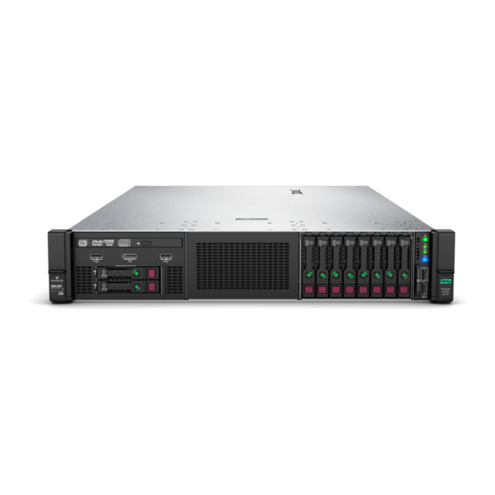
Component identification Front panel components Item Description Box 1 — Supported options: • Universal media bay components • Eight-bay SFF HDD drive cage Two-bay NVMe/Six-bay SFF HDD drive cage • Box 2 — Supported options: • Eight-bay SFF HDD drive cage •... -
Page 108: Universal Media Bay Components
Universal media bay components Item Description USB 2.0 port Video display port Optical disk drive (optional) Drives (optional) Requires the two-bay SFF (Premium) drive cage Drive bay numbering Eight-bay SFF HDD drive cage Component identification... - Page 109 Eight-bay SFF NVMe drive cage Two-bay NVMe/Six-bay SFF HDD drive cage Component identification...
-
Page 110: Front Panel Leds And Buttons
Front panel LEDs and buttons Power switch module Systems Insight Display module (optional) Item Description Status Power On/Standby button and Solid green = System on system power LED Flashing green (1 Hz/cycle per sec) = Performing power on sequence Solid amber = System in standby Off = No power present Health LED Solid green = Normal... -
Page 111: Uid Button Functionality
The UID button can be used to display the Server Health Summary when the server will not power on. For more information, see the latest HPE iLO 5 User Guide on the Hewlett Packard Enterprise website. Front panel LED power fault codes The following table provides a list of power fault codes, and the subsystems that are affected. -
Page 112: Systems Insight Display Leds
Subsystem LED behavior Removable HPE Smart Array SR Gen10 controller 6 flashes System board PCIe slots 7 flashes Power backplane or storage backplane 8 flashes Power supply 9 flashes Systems Insight Display LEDs The Systems Insight Display LEDs represent the system board layout. The display enables diagnosis with the access panel installed. -
Page 113: Systems Insight Display Combined Led Descriptions
Description Status NIC LEDs Off = No link to network Solid green = Network link Flashing green = Network link with activity If power is off, the front panel LED is not active. For status, see Rear panel LEDs. Power supply LEDs Off = Normal Solid amber = Power subsystem degraded, power supply failure, or input power lost. - Page 114 Systems Insight Display LED Health LED System power Status and color Processor (amber) Amber One or more of the following conditions might exist: • Processor in socket X has failed. • Processor X is not installed in the socket. • Processor X is unsupported.
-
Page 115: Drives
Systems Insight Display LED Health LED System power Status and color Power cap (off) — Amber Standby. Power cap (green) — Flashing green Waiting for power. Power cap (green) — Green Power is available. Power cap (flashing amber) — Amber Power is not available. -
Page 116: Hot-Plug Drive Led Definitions
Item Status Definition The drive is doing one of the following: Flashing green • Rebuilding • Performing a RAID migration • Performing a stripe size migration • Performing a capacity expansion • Performing a logical drive extension • Erasing Flashing amber/ The drive is a member of one or more logical drives and predicts the drive will fail. -
Page 117: Drive Guidelines
Item Status Definition No drive activity. Do not remove Solid white Do not remove the drive. Removing the drive causes one or more of the logical drives to fail. Removing the drive does not cause a logical drive to fail. Drive status Solid green The drive is a member of one or more logical drives. -
Page 118: Rear Panel Components
Rear panel components Rear panel with optional tertiary riser Item Description Primary PCIe riser slots 1-3 Secondary PCIe riser slot bays 4-6 (Optional) Tertiary PCIe riser slots 7-8 (Optional) Power supply 2 (PS2) Power supply 1 (PS1) Serial port iLO Management Port Video port Rear USB 2.0 ports (2) Rear USB 3.0 ports (2) -
Page 119: Rear Panel Leds
Item Description Power supply 2 (PS2) Power supply 3 (PS3, optional) Power supply 1 (PS1) Serial port iLO Management Port Video port Rear USB 2.0 ports (2) Rear USB 3.0 ports (2) FlexibleLOM (optional) Rear panel LEDs Component identification... -
Page 120: Power Supply Leds
Item Description Status Activity LED Off = No network activity Solid green = Link to network Flashing green = Network activity Link LED Off = No network link Green = Network link UID LED Solid blue = Activated Flashing blue: •... -
Page 121: Fan Bay Numbering
LED Status Description System is off or power supply has failed. Solid Green Normal Fan bay numbering Component identification... -
Page 122: System Board Components
System board components Item Description FlexibleLOM connector Primary PCIe riser connector (processor 1 required) x4 SATA port 1 x4 SATA port 2 Upper processor mezzanine connector — Power (2) Upper processor mezzanine connector — Signals (2) USB 3.0 (2) x1 SATA port x1 SATA port/optical port System maintenance switch Front USB 3.0 connector... -
Page 123: System Maintenance Switch Descriptions
Reserved (2) This connector can be used for the HPE Smart Storage Battery or the HPE Smart Storage Hybrid Capacitor. The energy pack connected to this connector provides backup power to the DIMM slots and controllers installed on the system board. -
Page 124: Processor, Heatsink, And Socket Components
Position Default Function 1, 2, 3 Off = No function On = Restore default manufacturing settings Reserved — Reserved — Reserved — Reserved — Reserved — Reserved To access the redundant ROM, set S1, S5, and S6 to On. When the system maintenance switch position 6 is set to the On position, the system is prepared to restore all configuration settings to their manufacturing defaults. -
Page 125: Dimm Slot Locations
DIMM slots are numbered sequentially (1 through 12) for each processor on the system and mezzanine boards. For specific DIMM population information, see the DIMM population guidelines on the Hewlett Packard Enterprise website (http://www.hpe.com/docs/memory-population-rules). System board DIMM slots Processor mezzanine board DIMM slots DIMM label identification To determine DIMM characteristics, see the label attached to the DIMM. - Page 126 Item Description Example Capacity 8 GB 16 GB 32 GB 64 GB 128 GB Rank 1R = Single rank 2R = Dual rank 4R = Quad rank 8R = Octal rank Data width on DRAM x4 = 4-bit x8 = 8-bit x16 = 16-bit Memory generation PC4 = DDR4...
-
Page 127: Hpe Persistent Memory Module Label Identification
R = RDIMM (registered) L = LRDIMM (load reduced) E = Unbuffered ECC (UDIMM) For more information about product features, specifications, options, configurations, and compatibility, see the HPE DDR4 SmartMemory QuickSpecs on the Hewlett Packard Enterprise website (https://www.hpe.com/support/ DDR4SmartMemoryQS). HPE Persistent Memory module label identification... -
Page 128: Nvdimm Identification
For more information about product features, specifications, options, configurations, and compatibility, see the product QuickSpecs on the Hewlett Packard Enterprise website (https://www.hpe.com/support/persistentmemoryQS). NVDIMM identification NVDIMM boards are blue instead of green. This change to the color makes it easier to distinguish NVDIMMs from DIMMs. -
Page 129: Nvdimm Led Identification
• (P) is the module part number. • (L) is the technical details shown on the label. • (S) is the module serial number. Example: (P)HMN82GR7AFR4N-VK (L)16GB 1Rx4 NN4-2666V-RZZZ-10(S)80AD-01-1742-11AED5C2 NVDIMM LED identification Item LED description LED color Power LED Green Function LED Blue NVDIMM-N LED combinations... -
Page 130: Drive Cage Backplane Identification
State Definition NVDIMM-N Function LED The restore operation is in progress. Flashing The restore operation is successful. Solid or On Erase is in progress. Flashing The erase operation is successful. Solid or On The NVDIMM-N is armed, and the NVDIMM-N is in normal Solid or On operation. - Page 131 Eight-bay SFF NVMe SSD drive cage backplane Two-bay NVMe/Six-bay SFF HDD (Premium) drive cage backplane Component identification...
-
Page 132: Riser Components
Two-bay SFF (Premium) drive cage backplane Riser components 4-port NVMe Slimline riser Item Description 1–4 x8 Slimline NVMe connectors Component identification... - Page 133 Three-slot with NVMe Slimline riser Item Description x8 Slimline NVMe connector Controller backup power connectors (3) 3–5 x8 PCIe slots Three-slot with M.2 riser Item Description GPU power cable connector Controller backup power connectors (3) M.2 SSD drive connectors x8 PCIe slot x16 PCIe slot x8 PCIe slot The riser supports installation of a second M.2 SSD drive on the reverse side.
- Page 134 Three-slot GPU riser Item Description GPU power cable connector Controller backup power connectors (3) x8 PCIe slot x16 PCIe slot x8 PCIe slot Two-slot GPU riser Item Description GPU power cable connector Controller backup power connectors (2) x16 PCIe slot x16 PCIe slot Component identification...
- Page 135 Two-slot x8 riser (tertiary) Item Description x8 PCIe slot x8 PCIe slot Controller backup power connectors (2) x8 riser (tertiary) Item Description x8 PCIe slot x8 Slimline NVMe connector Controller backup power connector Component identification...
-
Page 136: Hpe 12G Sas Expander Card Port Numbering
Dual Slimline riser (tertiary) Item Description x8 Slimline NVMe connector x8 Slimline NVMe connector HPE 12G SAS Expander Card port numbering Component identification... -
Page 137: Hpe Smart Array P824I-P Mr Gen10 Controller
HPE Smart Array P824i-p MR Gen10 Controller Components Item Description Internal SAS port 1i Internal SAS port 2i Internal SAS port 3i Internal SAS port 4i Controller backup power cable connector Internal SAS port 5i Internal SAS port 6i Component identification... -
Page 138: Hpe Infiniband Hdr/Ethernet 940Qsfp 56X16 Adapter Leds
HPE InfiniBand HDR/Ethernet 940QSFP 56x16 adapter LEDs Link LED status Description A link has not been established. Solid amber Active physical link exists Blinking amber 4 Hz blinking amber indicates a problem with the physical link. Solid green A valid logical (data activity) link exists with no active traffic. -
Page 139: Cabling
Cabling Cabling overview This section provides guidelines that help you make informed decisions about cabling the server and hardware options to optimize performance. CAUTION: When routing cables, always be sure that the cables are not in a position where they can be pinched or crimped. - Page 140 Option kit Cable part number* From Power cable part number 6 SFF HDD/2 SFF NVMe drive cage 869964-001 Drive backplane Primary riser 869953-001 (drive box 2) System board (SATA ports 1 and 2) P408i-a controller 6 SFF HDD/2 SFF NVMe drive cage 869973-001 Drive backplane Secondary riser...
- Page 141 12G SAS Expander 880028-001 Secondary riser — Ports 1 and 2 12G SAS Expander 880029-001 Tertiary riser — Ports 1 and 2 HPE Smart Array p824i-p MR Gen 10 — Controller Riser 881582-001 controller P00511-001 Drive backplane Primary riser, —...
- Page 142 * To order spare cables, use the following kits and spare part numbers. 2 SFF cable kit (877963-001) Small form factor (SFF) power cable (877960-001) MiniSAS cable kit (SFF) (877980-001) MiniSAS cable kit (SAS Expander) (877981-001) 28 AWG, 3 Pin, PCI to Controller power cable, short (878645-001) MiniSAS to MiniSAS HD, 12G cable kit (P03215-001) NVMe kits Option kit...
-
Page 143: Power Switch And Systems Insight Display Module Cabling
* To order spare cables, use the following kits and spare part numbers. Optical drive cable (784623-001) Power switch and Systems Insight Display module cabling HPE 12G SAS expander card cabling 24 SFF backplanes (Group C SAS cables) Cabling... - Page 144 18 SFF backplanes (Group C SAS cables) Cabling...
- Page 145 16 SFF backplanes (Group C SAS cables) Cabling...
-
Page 146: Eight-Bay Sff Hdd Drive Cage Cabling
Eight-bay SFF HDD drive cage cabling Drive box 1 cabling Connected to the system board (SATA ports 1 and 2) Cabling... - Page 147 Connected to the HPE P816i-a Smart Array controller Connected to the HPE P408i-a Smart Array controller Connected to the system board (SATA ports 1 and 2) Cabling...
- Page 148 Connected to the Smart Array controller Drive box 3 cabling Connected to the system board (SATA ports 1 and 2) Cabling...
-
Page 149: Eight-Bay Nvme Ssd Drive Cage Cabling
Connected to an HPE Smart Array controller Eight-bay NVMe SSD drive cage cabling Drive box 2 connected to the quad slimline riser installed in the primary PCIe riser cage Cabling... - Page 150 Drive box 2 connected to the quad slimline riser installed in the secondary PCIe riser cage Drive box 2 connected to the 4-port NVMe mezzanine card Cabling...
-
Page 151: Two-Bay Nvme/Six-Bay Sff Hdd Drive Cage Cabling
Two-bay NVMe/Six-bay SFF HDD drive cage cabling Quad slimline riser installed in the primary PCIe riser cage Quad slimline riser installed in the secondary PCIe riser cage Cabling... - Page 152 Tertiary riser Drive boxes 1–3 connected to the 4-port NVMe mezzanine card Cabling...
-
Page 153: Universal Media Bay Cabling
Universal media bay cabling Box 1 Universal media bay with optional optical drive cable (blue) Cabling... -
Page 154: Two-Bay Sff Hdd Drive Cage Cabling
Two-bay SFF HDD drive cage cabling Cabling... -
Page 155: Odd Drive Cabling
Orange System board energy pack cable This energy pack provides backup power to the components on the processor mezzanine tray. The energy pack used must be an HPE Smart Storage Battery. This energy pack provides backup power to the DIMM slots and controllers installed on the system board. The energy pack used can be either the HPE Smart Storage Battery or the HPE Smart Storage Hybrid Capacitor. -
Page 156: Hpe Smart Array Mr Gen10 Controller Cabling
HPE Smart Array MR Gen10 Controller cabling From the drive cage backplane to the controller in the primary PCIe riser cage From the drive cage backplane to the controller in the secondary PCIe riser cage Cabling... -
Page 157: Specifications
Specifications Environmental specifications Specification Value System Inlet Temperature, Standard Operating Support — Operating 10°C to 35°C (50°F to 95°F) Non-operating -30°C to 60°C (-22°F to 140°F) Relative humidity (non-condensing) — Operating Minimum to be the higher (more moisture) of -12°C (10.4°F) dew point or 8% relative humidity Maximum to be 24°C (75.2°F) dew point or 90% relative humidity... -
Page 158: System Inlet Temperature, Extended Ambient Operating Support
Power supply specifications Depending on installed options, the server is configured with one of the following power supplies: • HPE 800W Flex Slot Platinum Hot-plug Low Halogen Power Supply HPE 800W Flex Slot Titanium Hot-plug Low Halogen Power Supply •... -
Page 159: Hpe 800W Flex Slot Platinum Hot-Plug Low Halogen Power Supply
For detailed power supply specifications, see the QuickSpecs on the Hewlett Packard Enterprise website (http:// www.hpe.com/info/proliant/powersupply). HPE 800W Flex Slot Platinum Hot-plug Low Halogen Power Supply Specification Value Input requirements — Rated input voltage 100 VAC to 127 VAC 200 VAC to 240 VAC... -
Page 160: Hpe 800W Flex Slot Titanium Hot-Plug Low Halogen Power Supply
HPE 800W Flex Slot Titanium Hot-plug Low Halogen Power Supply Specification Value Input requirements — Rated input voltage 200 VAC to 240 VAC 240 VDC for China only Rated input frequency 50 Hz to 60 Hz Not applicable to 240 VDC Rated input current 4.35 A at 200 VAC 3.62 A at 240 VAC... -
Page 161: Hpe 800W Flex Slot -48Vdc Hot-Plug Low Halogen Power Supply
— Rated steady-state power 800 W at 200 VAC to 277 VAC input Maximum peak power 800 W at 200 VAC to 277 VAC input HPE 800W Flex Slot -48VDC Hot-plug Low Halogen Power Supply Specification Value Input requirements —... -
Page 162: Hpe 1600W Flex Slot Platinum Hot-Plug Low Halogen Power Supply
• Switching or disconnecting devices must not be in the earthed circuit conductor between the DC source and the point of connection of the earthing electrode conductor. HPE 1600W Flex Slot Platinum Hot-plug Low Halogen Power Supply Specification Value Input requirements... - Page 163 Specification Value Rated input current 8.7 A at 200 VAC 7.2 A at 240 VAC Maximum rated input power 1734 W at 200 VAC 1725 W at 240 VAC BTUs per hour 5918 at 200 VAC 5884 at 240 VAC Power supply output Rated steady-state power 1600 W at 200 VAC to 240 VAC input...
-
Page 164: Websites
Websites General websites Hewlett Packard Enterprise Information Library https://www.hpe.com/info/EIL Single Point of Connectivity Knowledge (SPOCK) Storage compatibility matrix https://www.hpe.com/storage/spock Storage white papers and analyst reports https://www.hpe.com/storage/whitepapers For additional websites, see Support and other resources. Websites... -
Page 165: Support And Other Resources
Support and other resources Accessing Hewlett Packard Enterprise Support • For live assistance, go to the Contact Hewlett Packard Enterprise Worldwide website: https://www.hpe.com/info/assistance • To access documentation and support services, go to the Hewlett Packard Enterprise Support Center website: https://www.hpe.com/support/hpesc Information to collect •... -
Page 166: Remote Support
IMPORTANT: Access to some updates might require product entitlement when accessed through the Hewlett Packard Enterprise Support Center. You must have an HPE Passport set up with relevant entitlements. Remote support Remote support is available with supported devices as part of your warranty or contractual support agreement. It provides intelligent event diagnosis, and automatic, secure submission of hardware event notifications to Hewlett Packard Enterprise, which will initiate a fast and accurate resolution based on your product's service level. -
Page 167: Documentation Feedback
Hewlett Packard Enterprise is committed to providing documentation that meets your needs. To help us improve the documentation, send any errors, suggestions, or comments to Documentation Feedback (docsfeedback@hpe.com). When submitting your feedback, include the document title, part number, edition, and publication date located on the front cover of the document.
Need help?
Do you have a question about the ProLiant DL560 Gen10 and is the answer not in the manual?
Questions and answers