
Related Manuals for Jaton 3DForceG-16


Summary of Contents for Jaton 3DForceG-16
- Page 1 3DForce G-16 3DForce G-32 3DForce G-16/TV 3DForce G-32/TV 3DForce XP multimedia accelerator User Manual version 6.00 Copyright © 2002 Jaton Corporation, USA.
- Page 2 NOTICE The information in this document is subject to change in order to improve reliability, design, or function without prior notice and does not represent a commitment on the part of the company. In no event will the company be liable for direct, indirect, special, incidental, or consequential damages arising out of the use or the inability to use the product or documentation, even if advised of the possibility of such damages.
-
Page 3: Table Of Contents
1. INTRODUCTION...5 2. FEATURES...6 2.1 AGP B NTERFACE 2.2 P (@800 MH ERFORMANCE 2.3 3D G RAPHICS NGINE 2.4 DVD S ...8 UPPORT 2.5 V ...8 IDEO NGINE 2.6 A DVANCED OWER 2.7 M EMORY NTERFACE 2.8 D 7.0...9 IRECT 2.9 S ...10 OFTWARE... - Page 4 10.1 A NALOG OLOR 10.2 C ONVERSION ABLE 10.3 9- -15 P ONVERSION 10.4 A NALOG IDEO 11. FCC SHIELDED CABLE WARNING ..46 11.1 T ECHNICAL UPPORT 12. LIMITED WARRANTY..48 12.1 O ...49 THER IMITS 12.2 E XCLUSIVE BLIGATION 12.3 O THER...
-
Page 5: Introduction
For maximum throughput, the 3DForce G-16/G-32/XP use full AGP 2x/4x bus interface that supports at up to 1.06 GByte per second transfer rate. Furthermore, 3DForce G-16/G-32/XP are subsistence Microsoft graphics standard - DirectX 7.0 Cubic mapping, and PC2001 compliant. Jaton Corporation, USA. -
Page 6: Features
2. Features 2.1 AGP Bus Interface Full AGP 2X/4X Support at up to 1.06 GByte/sec transfer rate DMA bus mastering support with Scatter Gather Execute Mode for Direct Textures, Video, and DVD Special impedance matching circuit for AGP-4X signaling 2.2 Performance (@800 MHz PIII with 128MB of memory) Pixel processing rate: 800 Million pixels/sec Texel access rate: 1,200 Million pixels/sec... - Page 7 2.3.1.1.2 Rendering 2.3.1.1.3 Texturing Dual independent 128-bit pixel pipelines (256-bit total) Single-pass processing of diffused, specular lighting and fog Enhanced Gouraud Shading & Phong-like environmental lighting Fast order-independent scene anti-aliasing support Fully OpenGL-compliant blending including fog & depth cueing Hidden surface removal with 16, 24, or 32-bit Z buffer or W buffer Color format includes 16, 24, or 32-bit per pixel Supports 8-bit stencil buffer...
-
Page 8: Dvd Support
2.3.1.1.4 2D GUI 2.4 DVD Support THAMA™ architecture enables full DVD player support Requires no extra frame buffer and minimum AGP bandwidth Includes both Motion Compensation and IDCT hardware assist Real-time playback (30fps) of 9.8 Mbps MPEG-2 video bitstream with 80% CPU headroom for other application Alpha blending for subpicture Advanced error recovery &... -
Page 9: Advanced Power Management
Capable of supporting HD0 HDTV resolution (1280x720) TrueVideo® bilinear interpolation with proprietary edge recovery scaling Dual apertures for simultaneous access to graphics and video display memory area Dual color space converters (CSC) Accelerates YUV planar format 2.6 Advanced Power Management 7 GPIOs, suspend and standby modes Internal clock gating on each functional block PCIPM (H/W PCI initiated) -
Page 10: Software
2.9 Software Window 98/Me, Window 2000/XP Windows NT 4.0 DirectX 6.0, 7.0 and 8.0 DirectShow 3.0 and 4.0 OpenGL ICD 1.0 and 1.2 3. Check List The package you have purchased should contain the following: þ 3DForce G-16, or 3DForce G-16/TV, or 3DForce G-32, or 3DForce G-32/TV, or 3DForce XP multimedia accelerator þ... -
Page 11: Hardware Description
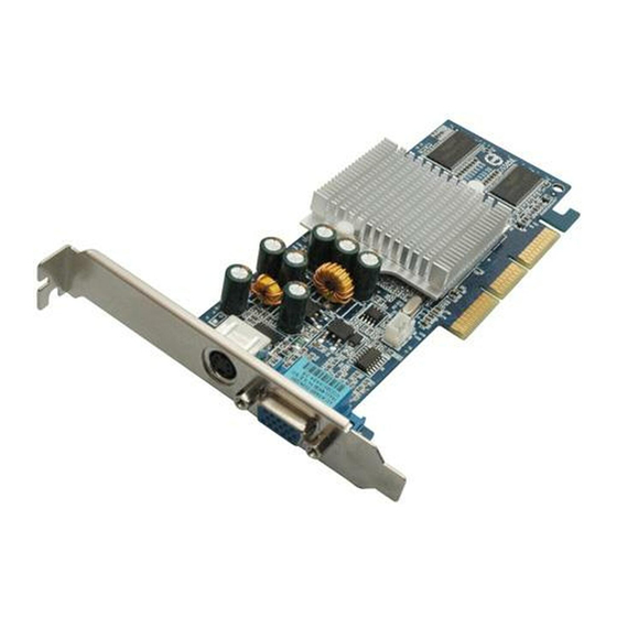
5. Hardware Description 5.1 Board Layout and Specification Plate TVOUT OPTIONAL RCA Video S_Video DB 15 VGA Product's Name PCB version 3DForce G-16 82117B 3DForce G-16TV 82117B 3DForce G-32 82117B 3DForce G-32TV 82117B 3DForce XP 82127B 5.2 Identify an AGP Slot (short and brown) Main board Width Core Chipset... -
Page 12: Display Devices Connection
5.3 Display Devices Connection Television PC Computer If your system is equipped with a sound board, you can also connect a Y-cable for speaker (single male mini stereo phono jack to double male RCA jack) from the Speaker-Out jack of the sound board to the Audio-In jack on your television set. -
Page 13: Hardware Installation
6. Hardware installation 6.1 Installation Procedures The manufacturer assumes no liability for any damage, caused directly or indirectly, by improper installation of any components by unauthorized service personnel. If you do not feel comfortable performing the installation, consult with a qualified computer technician. -
Page 14: Software Installation
going to use that expansion slot, you can install the slot cover you just removed from the unused expansion slot to cover the open hole. To install the adapter in the selected expansion slot, carefully line up the gold-fingered edge connector on the adapter directly above the expansion slot connector on the motherboard. - Page 15 Autorun feature pops-up “Welcome” screen as below, then you may click on “Display Driver ” selectable text to start the installation.
- Page 16 Click on Settings tab, then click on Advanced…button in lower portion of tab screen. Select Change… button in Adapter tab screen.
- Page 17 Install wizard will searching an updated driver for standard VGA adapter. Click the Next button now. Click on Next button with “Specify the location driver (Advanced) “ option to continue.
- Page 18 Click on Next button with “Display a list of all the drivers in a specific location, so you can select the driver you want” selectable option. Obedient to the select device page, press on "Have Disk..." button to specify the location of drivers. You can input D:\G1632&XP\WIN9X into the dialog box, and click on OK button.
- Page 19 Install wizard selected on "3DForce G-16/G-32/TV/XP (Trident Video Blade XP/T64)" to install, you may click on OK button. 10. Click Next to start transmit all driver files from software CD to your local hard disk drive.
-
Page 20: Microsoft Windows Nt™4.0
11. Click Finish to close the install wizard screen after all files have been copy over. ÿ ÿ 7.1.2 NT™4.0 ICROSOFT INDOWS Note: The procedure of display driver installation that is required “setup” with service pack4 or above (Microsoft® Windows NT™4.0) before install the video display driver. - Page 21 SELECT on the “Display Driver” from the picture above. TAB, or CLICK on the “Settings” screen page.
- Page 22 SELECT “Display Type...” button in the “Settings” page. SELECT “Change...” button from the Adapter type section.
- Page 23 SELECT “Have Disk...” button from the Change Display page. Microsoft Windows NT 4.0 will prompt you for the correct path where the video drivers are located. ENTER “D:\G-32&XP\Winnt4\” where D: is the letter of your CD ROM drive that the Software & Documents CD has been inserted.
- Page 24 Click on “OK” button, if the file source for driver is corrected. If the driver “3DForce G-16/G-32/TV/XP (Trident Video Blade- XP/T64)” is listed under the Display list, SELECT the “OK” button to continue.
-
Page 25: Microsoft Windows 2000
A screen message prompt that the conformation of your display driver has been in place for the new hardware. Click on “Yes”. 10. Click on “OK”. Once the driver files are copied, RESTART Microsoft Windows NT 4.0 for the changes to take effect. ÿ... - Page 26 1. Aoturun brings up the “Welcome” screen for your new display driver installation, click on “Display Driver” from this picture above. 2. Add New Hardware Wizard will pops-up, click on “ Next” to start the installation. 3. Checked “Add/Troubleshooting device” and click on “Next”...
- Page 27 4. Wizard has been found the new device, click on “Next” to continue. 5. Place the check mark to “search device from a list” then click on “Next”.
- Page 28 6. High light “Display adapter” and click on “Next”. 7. Wizard ask you to select device driver from its table, do not take any of them from that list. Click on “Have disk…” button to continue the process.
- Page 29 8. Browse and unfolded on CD sub-directories, or type “D:\G1632&XP\Win2000” into dialog box as above, then click on “OK”. (D is the letter of your CD_ROM drive, typically, D or E drives, etc.) 9. A confirmation screen for the device you have selected, click on “Next”...
- Page 30 10. A confirmation for digital signature was not embody all driver files (not necessarily to have that signature), click on “Yes” to continue installation. 11. Windows operating system will copying all...
- Page 31 files to the designation (local hard drive) drive. Click on “Next” now. 12. File transmission has been progress, please wait until it finished. 13. Click on “Finish” to complete the driver install process.
-
Page 32: Microsoft Windows Xp
14. Re-boot your computer is required for new display driver in places. ÿ ÿ 7.1.4 ICROSOFT INDOWS Microsoft Windows® XP detects this device and placed appropriate display driver from its operating system automatically, it doesn’t matter you have add a new or change the existing one. - Page 33 1. Aoturun brings up the “Welcome” screen for your new display driver installation, click on “Display Driver” from this picture above. 2. Add New Hardware Wizard will pops-up, click on “ Next” to start the installation.
- Page 34 3. Wizard searches the Plug-and-Play device information from its database. 4. Wizard has been found the new device, click on “Next” to continue. 5. Place the CD from manufacturer into your CD ROM drive, browse and unfolded on sub-...
- Page 35 directories, or type in “E:\G1632&Xp\winxp” into dialog box as above, then click on “Next”. 6. Wizard searches the source files for the new device.
- Page 36 7. Wizard has been listed the device to install, click on “Next” to continue the process. 8. A conformation screen that prompts to ensure...
- Page 37 the progress, click on “Continue Anyway”. 9. Windows operating system starts copy all files to the designation (local hard drive)drive.
-
Page 38: Technical Assistance (Q & A)
10. Click on “Finish” to complete the driver installation. 8. Technical Assistance (Q & A) Q: Why is the display shifted or changed sizes when I switch display modes? Some monitors lack auto-sizing features or just do not synchronize properly to the video board output. In some cases, horizontal and vertical display adjustments may be necessary. - Page 39 Q: Windows screen won’t come up, it kicks back to DOS prompt. Why? The SYSTEM.INI file may contain different information with the system hardware, cause by the new integration or the new installation of a video adapter. The SYSTEM.INI file is located in the WINODWS\SYSTEM directory.
-
Page 40: Tips
Most PCI/AGP video cards designed for Plug-n-Play, that means video card IRQ’s setup which controls by main board’s (mother board) circuitry and BIOS. Physically pulling out other devices from system, and re-start the computer. Confirm and modify your IRQ addresses with qualified computer technician. Q: Multiple images or unreadable screen after loading video driver. -
Page 41: Video Mode Reference Table
Ensure that the monitor or TV brightness and contrast controls are properly adjusted. Check to see if your monitor or TV is properly connected to the card. Be sure your monitor’s pin definitions match those of your video card. For TV out, ensure that the composite signal is connected to a “Video Input”... -
Page 42: Extended Modes
9.2 Extended Modes Mode Resolution -Colors 640x480-16 640x473-16 640x480-16 1056x350-16 1056x480-16 1056x473-16 1056x480-16 1188x350-16 1188x480-16 1188x473-16 1188x480-16 5Bh_1 800x600-16 640x400-256 5Dh_4 640x480-256 5Dh_3 640x480-256 5Dh_2 640x480-256 5Dh_1 640x480-256 5Eh_3 800x600-256 5Eh_2 800x600-256 5Eh_1 800x600-256 5Fh_5 1024x768-16 5Fh_4 1024x768-16 5Fh_3 1024x768-16 5Fh_2 1024x768-16 5Fh_1... - Page 43 Mode Resolution -Colors 66h_1 1600x1200-256 6Ah_1 800x600-16 640x400-16M 6Ch_4 640x480-16M 6Ch_3 640x480-16M 6Ch_2 640x480-16M 6Ch_0 640x480-16M 6Dh_3 800x600-16M 6Dh_2 800x600-16M 6Dh_1 800x600-16M 66h_2 1600x1200-256 6Eh_5 1024x768-16M 6Eh_4 1024x768-16M 6Eh_3 1024x768-16M 6Eh_2 1024x768-16M 6Eh_1 1024x768-16M 72/3h 640x400-32K/64K 74/5h_4 640x480-32K/64K 74/5h_3 640x480-32K/64K 74/5h_2 640x480-32K/64K 74/5h_1...
- Page 44 Mode Resolution -Colors 3Ch_0 320x240-16M 3Dh_3 400x300-16M 3Dh_2 400x300-16M 3Dh_1 400x300-16M 42/3h 320x200-32K/64K 44/5h_4 320x240-32K/64K 44/5h_3 320x240-32K/64K 44/5h_2 320x240-32K/64K 44/5h_1 320x240-32K/64K 46/7h_4 400x300-32K/64K 46/7h_3 400x300-32K/64K 46/7h_2 400x300-32K/64K 1. VESA mode. Same as 5Bh_1. 2. The “I” and “NI” in the vertical frequency column denote “interlaced” and “Non-interlace”, respectively.
-
Page 45: Pinout And Sync Frequencies
10. Pinout and Sync Frequencies 10.1 Analog Color Display Pinouts (DB 15) Note: Analog monochrome type monitors use green video for all video input and ignore red and blue video. 10.2 Conversion Table: Pin Adapters If you will be using a 9-to-15 pin adapter cable to link your 9 pin monitor connector to the 15 pin accelerator card connector, check Table carefully before you install the cable. -
Page 46: 9-To-15 Pin Conversion Table
10.3 9-to-15 Pin Conversion Table 9 PIN SIGNALS Green Blue Horz Sync Vert Sync Red Ground Green Ground Blue Ground Sync Ground 10.4 Analog Video Signals Black Level = 0 V Full Intensity (White) Level = +0.7 V 11. FCC SHIELDED CABLE WARNING This equipment has been tested and found to comply with the limits for a Class B digital device, pursuant to Part 15 of the FCC Rules. -
Page 47: Technical Support
In the event you have a technical problem with this product, please read the README files in the software CD-ROM. Updated drivers are available through Jaton BBS and Web site. Have following information handy when you contact technical support: þ... -
Page 48: Limited Warranty
(2) years from manufacturing date. This limited warranty applies only to the original purchaser of Jaton Product and is not transferable. This limited warranty does not apply if failure to the Product Registration, or over thirty (30) days from purchase (original invoice date). -
Page 49: Other Limits
Direct Jaton Customer: Reseller/ Vendor: Registered User: This warranty applies only for a period of two (2) years from purchase date of Jaton original invoice. This warranty applies only for a period of two (2) years from manufacturing date. This warranty applies only for a period of... -
Page 50: Services Agreement
Others: 12.5 Services agreement: (1) All applicants shall completed service request form from Manufacturer. (2) All returned checks would be charged a $20.00 fee by Manufacturer. (3) All repair and replacement services allow 4-6 weeks from the date of receiving by Manufacturer. (4) All products without warranties require service processing fee $20 (payment in advance), which is not refundable. - Page 51 Ask your dealer if there are any known problems with the system requirements or installation procedures for any add-on products that your are purchasing; Buy industry standard products where compatibility issue are more likely to surface; If you are unsure about installation for a new product, contact your dealer’s service department.
Need help?
Do you have a question about the 3DForceG-16 and is the answer not in the manual?
Questions and answers