
Related Manuals for Jaton Video-338PCI series


Summary of Contents for Jaton Video-338PCI series
- Page 1 Video-338/348PCI series NVIDIA GeForce™ 6200 series User’s Manual Version 10.00 C o p y r i g h t © 2 0 0 9 J a t o n C o r p o r a t i o n , U S A...
-
Page 2: Table Of Contents
Contents INTRODUCTION ................. 4 FEATURES AND SPECIFICATIONS ......... 5 SYSTEM REQUIREMENT ............9 CHECK LIST ................9 HARDWARE DESCRIPTION............ 10 DISPLAY DEVICES OUTPUT ..........15 ............20 NSTALLATION ROCEDURES : ..................20 TEPS SOFTWARE INSTALLATION........... 22 ® 7 ....22 INDOWS ISTA RIVER... - Page 3 .......... 41 OW TO BTAIN ARRANTY ERVICE LIMITED WARRANTY .............. 43 ................44 THER IMITS ............... 45 XCLUSIVE BLIGATION ..............45 THER TATEMENTS .............. 45 ERMS AND ONDITIONS :..............46 ERVICES AGREEMENT ..............46 NTIRE BLIGATION REDUCING WARRANTY CLAIM REJECTIONS..... 47...
-
Page 4: Introduction
NVIDIA UltraShadow II technology designed to enhance the performance of shadow-intensive games. Powered by the proven NVIDIA CineFX 3.0 engine, these advanced GPUs enable unlimited programmability and infinite program length, allowing develops to create new class of advanced visuals and effects. -
Page 5: Features And Specifications
CineFX 3.0 Engine The third-generation of the NVIDIA® CineFX™ engine unleashes the power of the latest NVIDIA GPUs and streamlines the creation of complex visual effects. Through the power of the Microsoft® DirectX® 9.0 Shader Model 3.0 and OpenGL® 1.5 APIs, programmers can now develop shader programs utilizing these technologies and techniques: Infinite length shader programs: With CineFX 3.0 there are... - Page 6 NVIDIA CineFX 3.0 is poised to unleash a new level of programming creativity. With full DirectX 9.0 Shader Model 3.0 support, the newest Video-338/348PCI series will soon power a new generation of games with unmatched realism, digital worlds with mind-blowing complexity, and lifelike characters that move through cinematic-quality environments.
- Page 7 The NVIDIA UDA guarantees forward and backward compatibility with software drivers. This simplifies upgrading to a new NVIDIA product because all NVIDIA products work with the same driver software. nView Multi-Display Technology The nView hardware and software technology combination delivers maximum flexibility for multi-display options and provides unprecedented end-user control of the desktop experience.
- Page 8 Dual 400MHz RAMDACs Blazing-fast RAMDACs support dual QXGA displays with ultra-high, ergonomic refresh rates–up to 2048x1536@85Hz. Compatibility • NVIDIA Unified Driver Architecture (UDA) • Fully compliant with OpenGL 1.5 • Microsoft DirectX 9.0 • WHQL-certified for Windows XP, Windows 2000, Windows...
-
Page 9: System Requirement
System Requirement • Intel Pentium® P4 or compatible system with PCI extension slot • Hard Drive with at least 200MB Free space • MS Windows® 7/Vista/XP/2000 operating system Check List • Video-338/348PCI series Multimedia Accelerator • Mini-DIN 9-pin (TV-Out) converter cable for Composite RCA or S-Video Out connection –... -
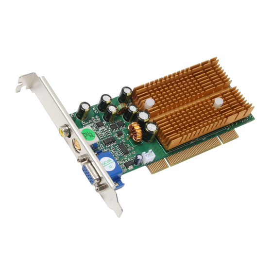
Page 10: Hardware Description
Hardware Description Video-338PCI-DVI Video-348PCI-DVI / Video-348PCI-256DVI Low profile configuration... - Page 11 Video-338PCI-LP Video-348PCI-LP / Video-348PCI-256LP Video-338PCI-TV / Video-338PCI-128TV Video-348PCI-TV / Video-348PCI-256TV...
- Page 12 Video-338PCI-Twin / Video-338PCI-128Twin Video-348PCI-Twin / Video-348PCI-256Twin Video-338PCI-LX / Video-338PCI-DX Video-348PCI-LX / Video-348PCI-DX DIM 9Pin VGA Display (RGB out) NVIDIA Memory DB 15 VGA (RGB out)
- Page 13 Video-348PCI-Quad...
- Page 14 Product name / PCB version Core Chipset PCB Size Memory Size Video-338PCI-DVI 82338P NVIDIA GeForce 6200A W=5.6” X H=2.54” 32M*16 x 4 DDR RAM 256MB Video-338PCI-LP 82338R NVIDIA GeForce 6200A W=4.82” X H=2.55” 32M*16 x 4 DDR RAM 256MB Video-338PCI-Twin...
-
Page 15: Display Devices Output
Display Devices Output Video-338PCI-DVI Video-348PCI-DVI / Video-348PCI-256DVI RGB out - DB15 VGA connector to analog monitor. DVI converts to RGB with DVI-RGB converter for Dual RGB out. DVI out - DVI connects to LCD display panel. TV-Out - MD4 connector converts S-Video to RCA Composite Output or direct connects S-Video to TV set. - Page 16 Low profile configuration RGB out - DB15 VGA connector to analog monitor. DVI converts to RGB with DVI-RGB converter for Dual RGB out. DVI out - DVI connects to LCD display panel. TV-Out - MD4 connector converts S-Video to RCA Composite Output or direct connects S-Video to TV set.
- Page 17 Video-338PCI-LP Video-348PCI-LP / Video-348PCI-256LP Video-338PCI-Twin / Video-338PCI-128Twin Video-348PCI-Twin / Video-348PCI-256Twin...
- Page 18 Video-338PCI-TV / Video-338PCI-128TV Video-348PCI-TV / Video-348PCI-256TV Video-338PCI-LX / Video-338PCI-DX Video-348PCI-LX / Video-348PCI-DX Converter Cable DIM-9Pin Monitor DB 15 VGA DB 15 VGA Connector Monitor...
- Page 19 Video-348PCI-Quad...
-
Page 20: Installation Procedures
Hardware Installation Installation Procedures !! WARNING!! Discharge static electricity by touching the GROUND such as metal part of your case connected with good power ground before you handle the electronic circuit boards. The manufacturer assumes no liability for any damage, caused directly or indirectly, by improper installation of any components by unauthorized service personnel. - Page 21 2. If you are installing the video card into a system that has a previous version of NVIDIA Display Driver. It is highly recommended to remove the previous driver before installing a new version. To remove previous driver safely with new video card installed please do the following: 1) Press F8 during Windows boot to select and enter SAFE mode.
-
Page 22: Software Installation
Software Installation ® Windows 7 and Vista Driver Installation InstallShield® Program: Microsoft Windows® 7 and Vista detects this new hardware and places appropriate display driver from its system folder automatically - it doesn’t matter if you have added a new driver or changed the existing one. To maximize the video board acceleration and increase its performance, you may install the manufacturer’s display driver as follows: 1. - Page 23 Click on “Next” to continue the process. Click on “Yes” to agree to license agreement and continue.
- Page 24 Click on “Finish” to complete the installation.
-
Page 25: Windows ® Xp Driver Installation
® Windows XP Driver Installation InstallShield® Program: Microsoft Windows® XP detects this new hardware and places appropriate display driver from its system folder automatically - it doesn’t matter if you have added a new driver or changed the existing one. To maximize the video board acceleration and increase its performance, you may install the manufacturer’s display driver as follows: * Please note your “Welcome Screen”... - Page 26 Microsoft InstallShield® Wizard has start loading its setup process; please wait until it has completed. Click on “Next” to continue the process.
- Page 27 The Windows system will copy all driver files from source media to your local hard disk; please wait until the process has completed. Click on “Finish” to restart your computer, the new display driver will be in place after Windows boots-up.
-
Page 28: Windows ® 2000 Driver Installation
® Windows 2000 Driver Installation InstallShield® Program: Microsoft Windows®2000 detects this new hardware and places appropriate display driver from its system folder automatically - it doesn’t matter if you have added a new driver or changed the existing one. To maximize the video board acceleration and increase its performance, you may install the manufacturer’s display driver as follows: * Please note your “Welcome Screen”... - Page 29 Microsoft InstallShield® Wizard has start loading its setup process; please wait until it has completed. Click on “Next” to continue the process.
- Page 30 Click on “Finish” to restart your computer, the new display driver will be in place after Windows boots-up. Video-348PCI-Quad --- 4 output display configuration – extended desktop display 1. Right click on desktop, go to Display properties > Settings page 2.
- Page 31 Notice: We believe that the all the installation steps mentioned above are clear from manufacturer software’s CD to your operating system. Any procedures other than these processes have not been specified.
-
Page 32: Technical Assistance
Technical Assistance Q: Why is the display shifted or changed sizes when I switch display modes? Explain and Suggestion: Some monitors lack auto-sizing features or just do not synchronize properly to the video board output. In some cases, horizontal and vertical display adjustments may be necessary. -
Page 33: Frequently Asked Questions (Faq)
system, and re-starts the computer. Confirm and modify your IRQ addresses with qualified computer technician. Q: Multiple images or unreadable screen after loading video driver. Explain and Suggestion: There are a variety of reasons why the display might be distorted. One common reason is a monitor mis-match. - Page 34 Q2 What does “Rendering Engine” mean? Answer “Rendering Engine” generically applies to the part of the graphics engine that draws 3D primitives, usually triangles. In most implementations, the rendering engine is responsible for interpolation of edges and "filling in" the triangle. Q3 What does the set-up engine do in a graphics controller? Answer A set-up engine allows drivers to pass triangles in the form of raw vertex...
- Page 35 Q6 What does "software 3D" mean? Answer Software 3D is generally used to mean using non-specific (2D) hardware in conjunction with the CPU to render for 3D applications. Some of these techniques allow usable 3D applications when high-powered and/or MMX™- equipped CPU's are employed along with special-case software optimization techniques.
-
Page 36: Pinout And Sync Frequencies
Pinout and Sync Frequencies Analog Color Display Pinouts (DB 15) FUNCTION Red Video 1 Green Video 1 Blue Video 1 Not Used Ground Red Return (ground) Green Return (ground) Blue Return (ground) Vcc (+5v DDC Power) Sync Return (ground) Monitor ID (not used) SDA (DDC support) Horizontal Sync Vertical Sync... -
Page 37: 9-To-15 Pin Conversion Table
9-to-15 Pin Conversion Table 9 PIN SIGNALS PIN NO. 15 PIN SIGNALS PIN NO. Green Green Blue Blue Horz Sync Horz Sync Vert Sync Vert Sync Red Ground Return Red Green Ground Return Green Blue Ground Return Blue Sync Ground Digital Ground Ground Analog Video Signals... -
Page 38: Digital Visual Interface (Dvi-I) Connector
Digital Visual Interface (DVI-I) Connector C1 C2 24 C3 C4 24 pin DVI FEMALE connector built-in onboard. Pin Number Signals TMDS Data 2 - TMDS Data 2 + TMDS Data 2 Shield No Connection No Connection DDC Clock DDC Data No Connection TMDS Data 1 - TMDS Data 1 +... - Page 39 TMDS Clock + TMDS Clock <...
-
Page 40: Technical Support
Technical Support In the event you have a technical problem with this product, please read the README files in the software CD_ROM. Updated drivers are available through Jaton Web site. Have following information handy when you contact technical support: Name of the product. Software Driver and Version. -
Page 41: How To Obtain Warranty Service
How to Obtain Warranty Service In the worldwide contact: www.jaton.com In United States contact: Jaton Corporation. Service Center 47677 Lakeview Blvd., Fremont, CA 94538 Tel: 510-933-8886 Fax: 510-933-8887 In Taiwan contact: Jaton Technology Co., Ltd. 10F, NO.194, SEC.3, TA TUNG RD., HIS-CHIH, TAIPEI, TAIWAN R.O.C. - Page 42 FCC SHIELDED CABLE WARNING: This equipment has been tested and found to comply with the limits for a Class B digital device, pursuant to Part 15 of the FCC Rules. Operation is subject to the following conditions: (1) this device may not cause harmful interference, and (2) this device must accept any interference received, including interference that may cause undesired operation, “SHIELD INTERFERENCE CABLE (S) MUST BE USED ACCORDING TO FCC 15.27©.”...
-
Page 43: Limited Warranty
Limited Warranty Manufacturer warrants that the products sold hereunder are free from defects in material and workmanship for a period of two (2) years from manufacturing date. This limited warranty applies only to the original purchaser of Jaton Product and is not transferable. -
Page 44: Other Limits
from or related to the exercise of professional judgment and skill, or data entered into or used with the Jaton Corp. products. TRADEMARK AND COPYRIGHT: This product incorporates copyright protection technology that is protected by U.S. patents and other intellectual property rights. Use of this copyright protection technology must be authorized by Macrovision, and is intended for home and other limited viewing uses only unless otherwise authorized by Macrovision. -
Page 45: Exclusive Obligation
Exclusive Obligation This warranty is exclusive. The sole and exclusive obligation of Manufacturer shall repair or replace the defective products in the manner and for the period provided above. Manufacturer shall not have any other obligation with respect to the Products or any part thereof, whether based on contract, tort, and strict liability or otherwise. -
Page 46: Services Agreement
replacement Products or replacement parts shall be at User’s expanse. Services agreement: (1) All applicants shall complete service request form from Manufacturer. (2) All returned checks will be charged a $20.00 fee by Manufacturer. (3) All repair and replacement services allow 4-6 weeks from the date of receiving by Manufacturer. -
Page 47: Reducing Warranty Claim Rejections
Reducing Warranty Claim Rejections To reduce the potential of incurring damages not covered by Manufacturers warranties, we strongly recommend the following: • Read your manuals before installing peripherals and/or before making changes to the machine’s configuration; • Ask your dealer if there are any known problems with the system requirements or installation procedures for any add-on products that your are purchasing;... - Page 48 Warranty Service Use Only Serial Number - ten or eleven digit code, the serial number consists of the following parts: Packaging Type Manufactured Date Code Production Numerical Code 00 8 000015 Year Month XXXXX-XXX-XX S/N: A008000015 xxxx/xxxx 00.0 XXXX XX XXXXXX Product Label and Manufactured Date Code...
Need help?
Do you have a question about the Video-338PCI series and is the answer not in the manual?
Questions and answers