
Related Manuals for Microsemi SyncServer S600


Summary of Contents for Microsemi SyncServer S600
- Page 1 SyncServer S600 ....SyncServer S650 ........ User’s Guide ....Revision B April, 2016 .... Part Number: 098‐00720‐000 .... User’s Guide updates are available at: www.microsemi.com/ftdsupport...
- Page 2 © 2016 Microsemi All rights reserved. Printed in U.S.A. All product names, service marks, trademarks, and registered trademarks used in this document are the property of their respective owners. ...
- Page 3 SyncServer S600 ........
- Page 4 Table of Contents Chapter 2 Installing Getting Started ..........38 Security Considerations for SyncServer S6x0 Installation .
- Page 5 Table of Contents Chapter 4 Web Interface System Information ..........62 Status / Information Windows .
- Page 6 Table of Contents reboot system ..........130 set service .
- Page 7 Table of Contents Chapter 7 Maintenance, Troubleshooting & Part Numbers Preventive Maintenance .........166 Safety Considerations .
- Page 8 Table of Contents GNSS Antenna Kits Specifications ....... . .208 GNSS Antennas with Internal LNA Specifications .
-
Page 9: Table Of Contents
Figures SyncServer S600 Front Panel ........26 SyncServer S600 Rear Panel - Single AC Version . - Page 10 List of Figures Set Brightness Screen .........58 3-10 Select Time Format Screen .
- Page 11 List of Figures 4-42 Admin - Email Configuration Window ......102 4-43 Admin - Banner Configuration Window ......103 4-44 Admin - Serial Port Configuration Window .
- Page 12 List of Figures SyncServer 600 Series User’s Guide 098-00720-000 Revision B – April, 2016...
- Page 13 Tables Timing Input/Output Module........34 Serial Port Connector Pin Assignments.
- Page 14 SyncServer S6x0 Quickship Part Numbers ......172 SyncServer S600 Build to Order Part Numbers.....172 SyncServer S650 Build to Order Part Numbers.
- Page 15 How to Use This Guide This section describes the format, layout, and purpose of this guide. In This Preface Purpose of This Guide Who Should Read This Guide Structure of This Guide Conventions Used in This Guide ...
- Page 16 Purpose of This Guide The SyncServer S6x0 User’s Guide describes the procedures for unpacking, installing, using, maintaining, and troubleshooting the Microsemi SyncServer S6x0. It also includes appendixes that describe alarms and events, the languages that you use to communicate with the SyncServer S6x0, default values, and other information.
- Page 17 How to Use This Guide Structure of This Guide Chapter, Title Description Chapter 5, Command Line Describes the CLI command conventions, functions, and features. Interface (CLI) Chapter 6, Provisioning Describes the commands and procedures required to provision the SyncServer S6x0 after installing the unit. Chapter 7, Maintenance, Contains preventive and corrective maintenance, and Troubleshooting &...
- Page 18 You must enter status commands for case-sensitive operating systems exactly as shown. personnel A word or term being emphasized. qualified Microsemi does not A word or term given special emphasis. recommend... SyncServer 600 Series User’s Guide 098-00720-000 Revision B – April, 2016...
- Page 19 How to Use This Guide Warnings, Cautions, Recommendations, and Notes Warnings, Cautions, Recommendations, and Notes Warnings, Cautions, Recommendations, and Notes attract attention to essential or critical information in this guide. The types of information included in each are explained in the following examples. Warning: To avoid serious personal injury or death, do not disregard warnings.
- Page 20 Questions For additional information about the products described in this guide, please contact your Microsemi representative or your local sales office. You can also contact us on the web at www.microsemi.com/ftdsupport. When this manual is updated the updated version will be available for downloading from Microsemi’s internet web site.
- Page 21 Toll-free in North America: 1-888-367-7966 Telephone: 408-428-7907 Fax: 408-428-7998 email: ftd.support@microsemi.com Internet: www.microsemi.com/ftdsupport Europe, Middle East, and Africa (EMEA) Microsemi FTD Services and Support EMEA Altlaufstrasse 42 85635 Hoehenkirchen-Siegertsbrunn Germany Telephone: +49 700 3288 6435 Fax: +49 8102 8961 533 E-mail: ftd.emeasupport@microsemi.com ftd.emea_sales@microsemi.com...
- Page 22 How to Use This Guide Related Documents and Information SyncServer 600 Series User’s Guide 098-00720-000 Revision B – April, 2016...
- Page 23 Chapter 1 Overview This chapter provides introductory information for the SyncServer S6x0. In This Chapter Overview – SyncServer S6x0 Key Features – Software Options – Security Features Physical Description Functional Description Configuration Management Alarms 098-00720-000 Revision B – April, 2016 SyncServer 600 Series User’s Guide...
- Page 24 SyncServer S600 Modern networks require accurate, secure and reliable time services as provided by the Microsemi SyncServer S600. The security hardened S600 network time server is purpose built to deliver exact hardware-based NTP time stamps. The unparalleled accuracy and security is rounded out with outstanding ease-of-use features for reliable network time services ready to meet the needs of your network and business operations today and tomorrow.
- Page 25 LAN1 port to gain access to the licensed software options web page. Security Features Security is an inherent part of the SyncServer S600/S650 architecture. In addition to standard security features related to the hardening of the web interface, NTP and server access, unsecure access protocols are deliberately omitted from the S6x0 while remaining services can be disabled.
-
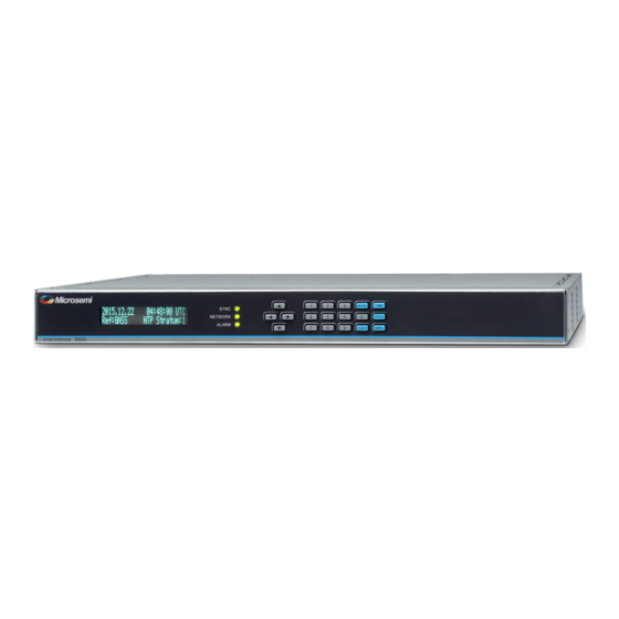
Page 26: Syncserver S600 Front Panel
Single AC version of the SyncServer S600. Figure 1-6 shows the rear panel connections for the Dual AC version of the SyncServer S600. Figure 1-1. SyncServer S600 Front Panel Figure 1-2. SyncServer S600 Rear Panel - Single AC Version SyncServer 600 Series User’s Guide... -
Page 27: Syncserver S600 Rear Panel - Dual Ac Version
Chapter 1 Overview Physical Description Figure 1-3. SyncServer S600 Rear Panel - Dual AC Version Figure 1-4. SyncServer S650 Front Panel Figure 1-5. SyncServer S650 Rear Panel - Single AC Version Figure 1-6. SyncServer S650 Rear Panel - Dual AC Version 098-00720-000 Revision B –... -
Page 28: Serial Port Connector
GNSS Connection The SyncServer S6x0 features a BNC connector for input from GNSS navigation satellites to provide a frequency and time reference. This port also provides 9.7V to the power a Microsemi GNSS antenna (see Antenna Kits Overview Appendix C, Installing GNSS Antennas). -
Page 29: Ntp Input/Output Connections
The dedicated Data/Timing port is provided to output NMEA-0183 or NENA PSAP strings. If NENA is selected, the serial Console port also supports the two-way timing aspects of the standard. In addition, the F8 and F9 Microsemi legacy time strings are available. -
Page 30: Alarm Relay Connectort
Chapter 1 Overview Physical Description Alarm Relay The SyncServer S6x0 features a Phoenix connector for an alarm relay output. See Figure 1-12. The relay is energized (shorted) when the configured alarm classes (Figure 1-13) occur. If the SyncServer S6x0 is not powered, then the alarm relay will be open. -
Page 31: Timing I/O Module Bnc Connectors
Chapter 1 Overview Physical Description Figure 1-14. Timing I/O Module BNC Connectors Figure 1-15. Signal Types for Timing I/O Module Power and Ground Connections The SyncServer S6x0 is available with either single or dual 120/240 VAC power. The SyncServer S6x0 is not equipped with a Power switch. AC power is controlled by the unplugging the AC power cord. -
Page 32: Syncserver S6X0 Single Ac Version Power And Ground
Chapter 1 Overview Functional Description Figure 1-16. SyncServer S6x0 Single AC Version Power and Ground Figure 1-17. SyncServer S6x0 Dual AC Version Power and Ground Functional Description LEDs The SyncServer S6x0 provides three LEDs on the front panel, as shown in Figure 1-18, that indicate the following: Sync Status... - Page 33 Chapter 1 Overview Functional Description Figure 2-5 for details about the LEDs. Communication Ports Communication ports on the SyncServer S6x0 allow you to provision, monitor, and troubleshoot the chassis with CLI commands. Management Ethernet Port The system web interface for full control is located on Ethernet port 1 (LAN1) and is used as the Management Ethernet connector to provide connectivity to an Ethernet local area network.
-
Page 34: Timing Input/Output Module
Chapter 1 Overview Configuration Management Frequency and Timing Outputs The SyncServer S6x0 can provide NTP,10 / 5 / 1 MHz, 1PPS, IRIG, or TOD output signals. The NTP signals use the RJ45 (1 - 4) connectors on the rear panel. The serial TOD output connects to a DB9 connector (DATA/SERIAL) on the rear panel. -
Page 35: Web Interface - Dashboard
Chapter 1 Overview Configuration Management Web Interface The SyncServer S6x0 also allows the user to access information via the LAN1 Ethernet port using HTTPS protocol. To use the SyncServer S6x0 web interface, enter the IP address for Ethernet port 1 into a web browser. Enter your user name and password for the SyncServer S6x0 when prompted. - Page 36 Chapter 1 Overview Alarms Alarms The SyncServer S6x0 uses alarms to notify you when certain conditions are deteriorating below specified levels or when issues arise, such as loss of power or loss of connectivity. These alarms are indicated by LEDs, WebGUI status, CLI status, alarm connector (configurable), SNMP Trap (configurable), message log (configurable), and email (configurable).
- Page 37 Chapter 2 Installing This chapter describes the procedures for installing the SyncServer S6x0. In This Chapter Getting Started Unpacking the Unit Rack Mounting the SyncServer S6x0 Installation Check List Signal Connections – Communications Connections – SyncServer S6x0 Synchronization and Timing Connections Connecting the GNSS Antenna ...
- Page 38 Getting Started Getting Started Before you begin to install the SyncServer S6x0, review the information in this section. If you encounter any difficulties during the installation process, contact Microsemi Frequency and Time Division (FTD) Services and Support. See Contacting Technical Support, on page 177 for telephone numbers.
- Page 39 1. Wear a properly grounded protective wrist strap or other ESD device. 2. Inspect the container for signs of damage. If the container appears to be damaged, notify both the carrier and your Microsemi distributor. Retain the shipping container and packing material for the carrier to inspect.
-
Page 40: Syncserver S6X0 - Location Of Product Label
See Figure 2-1 for the location of the label on the SyncServer S6x0. Contact your Microsemi distributor if the model or item number do not match. For a complete listing of item numbers, see... -
Page 41: Dimensions For Syncserver S6X0
Chapter 2 Installing Rack Mounting the SyncServer S6x0 Figure 2-2. Dimensions for SyncServer S6x0 Figure 2-3. Rack Mounting the SyncServer S6x0 098-00720-000 Revision B – April, 2016 SyncServer 600 Series User’s Guide... -
Page 42: Syncserver S600/S650 Power & Ground Connections - Single Ac
SyncServer S6x0, as shown in Figure 2-4 Figure 2-5. Figure 2-4. SyncServer S600/S650 Power & Ground Connections - Single AC Version Figure 2-5. SyncServer S600/S650 Power & Ground Connections - Dual AC Version Figure 2-6. Universal Ground Symbol After installing the SyncServer S6x0 into the rack, connect the chassis to the proper grounding zone or master ground bar per local building codes for grounding. - Page 43 Ground on the rack. The rack grounding method is below. Recommendation: Although there are a number of methods for connecting the equipment to earth ground, Microsemi recommends running a cable of the shortest possible length from the ground lug to earth ground.
-
Page 44: Syncserver S6X0 Single Ac Power Connector
Chapter 2 Installing Signal Connections AC Power Connection Use the following procedure to make the power connections for the AC version of the SyncServer S6x0. An Over-Current Protection Device must be placed in front of the shelf power. Figure 2-7. SyncServer S6x0 Single AC Power Connector Figure 2-8. -
Page 45: Serial Port Male Mating Connector Pins
Chapter 2 Installing Signal Connections Communications Connections The communication connections allow user control of the SyncServer S6x0. The EIA-232 serial port and Ethernet port 1 (LAN1) are located on the rear panel are shown in Figure 1-5. Ethernet Port 1 Ethernet port 1 is a standard 100/1000 Base-T shielded RJ-45 receptacle on the rear panel of the unit. -
Page 46: System Management Ethernet Connector Pin Assignments
Chapter 2 Installing Signal Connections SyncServer S6x0 Synchronization and Timing Connections The SyncServer S6x0 has one GNSS input and four NTP input/output connections. The SyncServer S6x0 has one 1PPS output. The SyncServer S650 may also have an optional Timing I/O Module. GNSS Connection To connect a GNSS signal to the SyncServer S6x0, you must install a GPS antenna. -
Page 47: Ethernet Connections
Chapter 2 Installing Signal Connections Figure 2-11. Ethernet Connections Timing I/O Module Connections The standard configuration offers a broad yet fixed selection of signal I/O on its eight BNC connectors (see Figure 1-14). J1 is dedicated to time code and rate inputs, J2 to sine wave inputs, and J3-J8 to mixed signal outputs. -
Page 48: Data/Timing Connection
Chapter 2 Installing Signal Connections Serial Timing Connection The SyncServer S6x0 features a DB-9 female connector on the rear panel of the unit. This port supports a baud rate of 4800 to 115.2k (115200-8-1-N-1). When connecting to this port, use a shielded serial direct connect cable. See Figure 2-13. -
Page 49: Gnss Input Connection
Chapter 2 Installing Connecting the GNSS Antenna Connecting the GNSS Antenna Caution: The GNSS cables should only be connected while the unit is properly earth grounded. The antenna connections for the SyncServer S6x0 are made at the BNC female connector labeled GNSS. Allow at least one hour for the unit to track and lock to GNSS satellites, though it typically takes far less time provided the antenna has an adequate view of the sky. -
Page 50: Alarm Connections
Chapter 2 Installing Installation Check List Figure 2-16. Alarm Connections Installation Check List To verify that the installation of the SyncServer S6x0 is complete, perform the checks and procedures in Table 2-4. Table 2-4. Installation Completeness Checklist Operation Complete Ensure the SyncServer S6x0 chassis is securely attached to mounting rack Verify that all power and ground wires are installed correctly and securely Verify that all communications cables are properly installed Verify that all input and output cables are properly installed... - Page 51 Chapter 2 Installing Applying Power to the SyncServer S6x0 Table 2-5. LED Descriptions (Continued) Label Description NETWORK Network Status Red - Management port (LAN1) is not configured or is down Amber - Some configured ports are down (LAN2 to LAN4) Green - All configured ports are up ALARM Alarm...
- Page 52 Chapter 2 Installing Applying Power to the SyncServer S6x0 SyncServer 600 Series User’s Guide 098-00720-000 Revision B – April, 2016...
- Page 53 Chapter 3 Keypad / Display Interface This chapter describes the keypad / display interface. Overview The keypad / display interface displays the time, system status, and provides the following functions: Configuring and enabling/disabling the LAN1 network port. Setting the time and entering freerun mode. ...
- Page 54 Chapter 3 TIME Button TIME Button Cycling the TIME button changes the predefined format and contents of the time display: Large numeric time display on full screen. Hours:Minutes:Seconds Medium numeric time display on the left, current reference and NTP Stratum on the right Small date and time, reference, and NTP stratum.
-
Page 55: Ntp Status Screen
Chapter 3 STATUS Button Figure 3-1. NTP Status Screen Some screens have a "Next>" in the upper right. This means more information is available by pressing the right arrow button. This cycles through screens on that topic. To continue through the topics, press STATUS or and up or down arrow at anytime. - Page 56 Chapter 3 STATUS Button LAN Status Screens Multiple screens, four for each network port. There are two screen for IPv4 and two for IPv6. Use Next> to see the entire IP address configuration. State: Shows “Up” if the port is enabled and “Down” if the port is disabled. IP: IP address for the port SM: Subnet mask GW: Gateway address...
-
Page 57: Menu Of Functions
Chapter 3 MENU Button MENU Button Pressing the MENU button presents a numbered menu of functions, as shown in Figure 3-2. Figure 3-2. Menu of Functions LAN1 Selecting LAN1 brings up the Display menu screen on the display, as shown in Figure 3-3. -
Page 58: Select Ipv4 Addressing Type Screen
Chapter 3 MENU Button Figure 3-5. Select IPv4 Addressing Type Screen 1. Static Addr: Select IPv4address mode for LAN1 port. If Static Address is selected, the Enter LAN1 Address screen will appear, as shown in Figure 3-6. After the address is entered press the ENTER button and you will be prompted to enter the Subnet mask (then ENTER) followed by the Gateway address. -
Page 59: Select Time Format Screen
Chapter 3 MENU Button 3. 12/24 (non-UTC Only): Select a 12 (AM/PM) or 24-hour clock format. See Figure 3-10. Note: The 12/24 and 24 Hour only appear if a local time zone has been specified via the web inteface. Figure 3-10. Select Time Format Screen Many keypad functions timeout after approximately 10 seconds of inactivity (no user inputs). -
Page 60: Keypad Control Display Screen
Chapter 3 MENU Button Figure 3-13. Keypad Control Display Screen 1. Set Password: Sets the password for the Lockout function. The *first time* the interface asks for the "Current Password", enter 95134. No password recover or reset feature is available for the keypad, except to reset factory defaults using the Sys Control - Factory Reset page. -
Page 61: Dashboard Screen
Depending on the browser used, the web page responsiveness will vary due to the use of the encryption cipher suite used in the S6x0. Microsemi recommends using the Google Chrome browser. 098-00720-000 Revision B – April, 2016 SyncServer 600 Series User’s Guide... -
Page 62: System Status
Chapter 4 System Information System Information The System information window in the Dashboard, as shown in Figure 4-2, displays an overall summary of the system. Figure 4-2. System Status Status / Information Windows The Status/Information windows in the dashboard, as shown in Figure 4-3, displays status details and information regarding the following:... -
Page 63: Status/Information Windows
Chapter 4 Status / Information Windows Figure 4-3. Status/Information Windows Timing Status & Information The Timing window in the dashboard, as shown in Figure 4-4, displays status details and information about system timing, including current reference, lock status, and status of input references. See Table 4-1. -
Page 64: Timing Window Descriptions
Chapter 4 Status / Information Windows Table 4-1. Timing Window Descriptions Item Details Color Scheme Time of Day Status This row is essentially showing the Warmup time clock state. Freerun Handset Table 4-2 for descriptions of Locking clock states. Locked Bridging Holdover Holdover... -
Page 65: Status - Clock State Descriptions
Chapter 4 Status / Information Windows Table 4-2. Status - Clock State Descriptions Status Indication Meaning Details Warmup SyncServer not ready for any type of Directly equal to the common synchronization functionality. This is a warmup clock state (to both freq one-time status following power-up and time) Freerun... -
Page 66: Status - Current Source Details
Chapter 4 Status / Information Windows Table 4-2. Status - Clock State Descriptions Status Indication Meaning Details Holdover Same as prior row but specific additional The unit has been in holdover conditions are met. for more than a user-specified duration and the holdover is This condition occurs if the current based on the SyncServer source is the internal oscillator and the... - Page 67 Chapter 4 Status / Information Windows Table 4-3. Status - Current Source Details Status Where it Will Item Details Happen Current Source taken Locking When the status is any of these there from Timing Sources MUST be a selected time source, which Locked takes precedence in the Current Source Relocking...
-
Page 68: Gnss Window
Chapter 4 Status / Information Windows Figure 4-5. GNSS Window Network Status & Information The Network window in the dashboard, as shown in Figure 4-6, displays status details and information about the network ports in use. Figure 4-6. Network Window NTP Status &... -
Page 69: Ntp Window
Chapter 4 Status / Information Windows Figure 4-7. NTP Window Alarm Information The Alarms window in the dashboard, as shown in Figure 4-8, displays active alarms. Figure 4-8. Alarms Window Slot Modules Status & Information The Slot Modules window in the dashboard, as shown in Figure 4-9, displays status details about the modules installed in the Options Slots. -
Page 70: About Window
Chapter 4 Navigation Windows Figure 4-10. About Window Note: The update available feature will only function if LAN1 has been configured with an IPv4 address and a DNS server is configured. The DNS server can be either automatically configured via DHCP or manually when using a static IP address. The update available feature can be disabled on the Admin->General page. -
Page 71: Network - Ethernet Configuration Window
Chapter 4 Navigation Windows Network Configuration Windows The Network tab on the dashboard provides access to windows for Ethernet, SNMP, SNMP Trap configuration, and Ping. Network - Ethernet Configuration Use this window to configure or modify the Ethernet setting for LAN1 - LAN4, and to manually set the DNS server address for LAN1. - Page 72 Chapter 4 Navigation Windows Network - SNMP Configuration Use this window to add, edit or delete SNMP users, and v2 communities. The following SNMP parameters can be configured: Basic Configuration – sysLocation, 1-49 characters – sysName, 1-49 characters – sysContact, 1-49 characters –...
-
Page 73: Network - Snmp Window
Chapter 4 Navigation Windows Figure 4-13. Network - SNMP Window Network - SNMP Trap Configuration Use this window add or edit SNMP trap recipients The following parameters can be configured: IP Address - up to 10 trap managers can be added ... -
Page 74: Network - Snmp Traps
Chapter 4 Navigation Windows Figure 4-14. Network - SNMP Traps SyncServer 600 Series User’s Guide 098-00720-000 Revision B – April, 2016... -
Page 75: Network - Ping Window
Chapter 4 Navigation Windows Network - Ping Use this window to perform network ping tests. Use ping to test network connectivity out the LAN ports as needed. The result of the ping will be displayed in the window when completed. Figure 4-15. -
Page 76: Ntp Sysinfo Window
Chapter 4 Navigation Windows NTP Configuration Windows The NTP tab on the dashboard provides access to windows to configure NTP, view NTP Daemon Status and Control, and to view NTP Associations. NTP SysInfo Window Use this window to view NTP Daemon Status and Control. Figure 4-16. -
Page 77: Ntpd Sysinfo Parameter Descriptions
Chapter 4 Navigation Windows Table 4-4. NTPd SysInfo Parameter Descriptions Parameter Description System Peer The IP address of the clock source. The source is selected by the NTP daemon that is most likely to provide the best timing information based on: stratum, distance, dispersion and confidence interval. - Page 78 Chapter 4 Navigation Windows Table 4-4. NTPd SysInfo Parameter Descriptions (Continued) Parameter Description Leap Indicator The Leap Indicator (LI) is a two-bit binary number in the NTP packet header that provides the following information: Advance warning that a leap second adjustment will be made to the UTC ...
- Page 79 Chapter 4 Navigation Windows Table 4-4. NTPd SysInfo Parameter Descriptions (Continued) Parameter Description Root Delay This is a measure of the total round trip delay to the root of the synchronization tree. A typical value for a SyncServer operating at stratum 1 would be 0 since the SyncServer is a root of the synchronization tree For other stratum levels, an appropriate value is displayed.
-
Page 80: Ntpd Associations Window
Chapter 4 Navigation Windows Figure 4-17. See Table 4-5for descriptions of NTPd Associations parameters. Figure 4-17. NTPd Associations Window Table 4-5. NTPd Associations Parameters Parameter Description Remote The domain name or IP address of the remote end of the NTP association. "Hardware Clock"... - Page 81 Chapter 4 Navigation Windows Table 4-5. NTPd Associations Parameters Parameter Description Stratum The stratum level of the remote clock in the NTP hierarchy. Lower values are given more emphasis. For the local Hardware Clock, stratum 0 is a special value that indicates the Hardware Clock it is synchronized by a "timing root"...
-
Page 82: Ntp Configuration Window
Chapter 4 Navigation Windows NTP Configuration Window Use this window to configure NTP parameters. Figure 4-18. Figure 4-18. NTP Configuration Window Click the Save button after making changes to save the changes. Click the Restart button to apply the changes. SyncServer 600 Series User’s Guide 098-00720-000 Revision B –... -
Page 83: Ntp Reflector Port Configuration Window
The unit will not respond to IPv4 NTP packets if the reflector is enabled for IPv6. The unit will not respond to IPv6 NTP packets if the reflector is enabled for IPv4. The SyncServer S600 Series implements real-time, hardware-based network packet processing in tandem with accurate hardware based NTP time stamping, general packet limiting and alarming. -
Page 84: Ntp Packet Reflector
Chapter 4 Navigation Windows The NTP Reflector is a real-time, hardware-based NTP packet identification and time-stamping engine. The high capacity hardware uses the extremely accurate S600 Series clock to deliver the best possible NTP timestamps. At line speed, NTP client packets are identified, the precise and accurate T2 and T3 time stamps are added and the packets returned to the requesting NTP client, while also bandwidth-limiting all other packets to the CPU. - Page 85 Chapter 4 Navigation Windows It is important to note that NTP is UDP/IP and is by nature susceptible to DoS attacks as no TCP/IP connection is required. The Security-Hardening of the line speed NTP Reflector is such that in the event of an NTP DoS attack the NTP packets will not reach the CPU and compromise the server operation.
- Page 86 Chapter 4 Navigation Windows Timing Configuration Windows The Timing tab on the dashboard provides access to windows to enable time and holdover sources, manually set time, set the time zone, and to configure format of the serial output. Note: The SyncServer 6x0 does not contain a battery-backed real time clock.
-
Page 87: Timing - Input Control Window
Chapter 4 Navigation Windows Figure 4-21. Timing - Input Control Window Timing - Holdover Configuration Window Use this window to configure a duration in holdover (loss of stratum 0 reference) until the server either unlocks or attempts to get time from other NTP servers (if configured to do so). -
Page 88: Timing - Time Zone Window
Chapter 4 Navigation Windows Holdover occurs when the input references (GNSS, etc.) are not available and microprocessor is steering the internal oscillator (standard, OCXO, Rubidium). During holdover the clock accumulates error (drifts away from perfect). By adjusting the values you can explore the relationship of holdover in days and clock error for the installed oscillator. -
Page 89: Timing - Serial Output Window
Chapter 4 Navigation Windows Figure 4-24. Timing - Serial Output Window References Configuration Window The References tab on the dashboard provides access to configure GNSS position and operating mode, as well as view Reference Status. References - Reference Status Window Use this window to view status information for system References. -
Page 90: References - Gnss Window
Chapter 4 Navigation Windows References - Reference GNSS Window Use this window to configure GNSS position and operating mode. See Figure 4-26. Note: For accurate timing, it is important to accurately enter the delay of the antenna and cable. If the system has already locked to a reference, then it is recommended that the user restart the SyncServer after changing the cable delay. - Page 91 Chapter 4 Navigation Windows Security Configuration Windows The Security tab on the dashboard provides access to configure security for Users, Access Control, Services & System Control, HTTPS, SSH, NTPd Symmetric Key, NTPd Autokey Server, NTPd Autokey Client, RADIUS, TACACS+, and LDAP. Security - Users Window Use this window to add or delete users, and for Password Maintenance.
-
Page 92: Security - Users Configuration Window
Chapter 4 Navigation Windows Figure 4-27. Security - Users Configuration Window Security - Access Control Configuration Window Use this window to configure access control for LAN1-LAN4 (whitelist). If nothing is configured, then the unit will accept data from all devices. If any addresses are configured, only packets from those devices will be accepted. -
Page 93: Security - Services & System Control Configuration Window
Chapter 4 Navigation Windows Figure 4-29. Security - Services & System Control Configuration Window Security - HTTPS Configuration Window Use this window to configure the web server and certificate info. See Figure 4-30. Note Number of allowed characters: Common name: 1-63 characters ... -
Page 94: Security - Ssh Configuration Window
Chapter 4 Navigation Windows Security - SSH Configuration Window Use this window to configure SSH security. See Figure 4-31. Figure 4-31. Security - SSH Configuration Window Security - NTPd Symmetric Keys Configuration Window Use this window to generate, upload and download NTP Symmetric Security Keys. Figure 4-32. -
Page 95: Security - Ntpd Autokey Server Configuration Window
Chapter 4 Navigation Windows Figure 4-33. Security - NTPd Autokey Server Configuration Window Security - NTPd Autokey Client Configuration Window Use this window to configure the NTP Autokey Client and install the IFF Group Key file. See Figure 4-34. Figure 4-34. Security - NTPd Autokey Client Configuration Window Security - RADIUS Configuration Window Use this window to enable and configure RADIUS authentication. -
Page 96: Security - Radius Configuration Window
Chapter 4 Navigation Windows Figure 4-35. Security - RADIUS Configuration Window Security - TACACS+ Configuration Window Use this window to enable and configure TACACS+ authentication. Up to 5 TACACS+ servers can be configured. See Figure 4-36. Note: TACACS+ key: 1-16 characters ... -
Page 97: Security - Ldap Configuration Window
Chapter 4 Navigation Windows Security - LDAP Configuration Window Use this window to enable LDAP, and configure LDAP settings and servers. Up to 5 LDAP servers can be configured. Note: Search base name: 1-63 characters binddn: 1-63 characters bindpw: 1-63 characters ... -
Page 98: Security - Packet Monitoring Window
Chapter 4 Navigation Windows Security - Packet Monitoring Use this window to configure packet load monitoring thresholds. The All Packets threshold is used to limit the number of packets from each port that are sent to the processor. It will also generate the “Excessive traffic on port” alarm if the threshold is exceeded, and identify the impacted port. -
Page 99: Admin - General Configuration Window
Figure 4-39. Enables the SyncServer to check the Microsemi upgrade notification site at http://update.microsemi.com every day at noon local time for new software updates. Displays a notice on the Status page and can send and SNMP trap when an upgrade is available. Requires that the SyncServer management port have firewall access to the internet. -
Page 100: Admin - Alarm Relay Configuration Window
Chapter 4 Navigation Windows Figure 4-40. Admin - Alarm Relay Configuration Window Admin - Alarm Configuration Window Use this window to configure system alarms. Users can also see the current status of each alarm and clear individual alarms. Use the scroll control on this form to access additional alarms. -
Page 101: Alarm Configuration Parameter Descriptions
Chapter 4 Navigation Windows Table 4-7. Alarm Configuration Parameter Descriptions Parameter Description Name Name of the alarm. If there is an asterisk as first character it means it is a transient alarm. For alarms that have multiple secondary info (e.g. Excessive Traffic on Ethernet port has a secondary field that identifies which port), these settings are global to all of the secondary cases. -
Page 102: Admin - Email Configuration Window
Chapter 4 Navigation Windows Table 4-7. Alarm Configuration Parameter Descriptions (Continued) Parameter Description Write Log Provides "per alarm" user control of reporting the alarm by writing an event entry in the Log. All severities and transients are reported into the message log. Send Email Provides "per alarm"... -
Page 103: Admin - Banner Configuration Window
Chapter 4 Navigation Windows Figure 4-43. Admin - Banner Configuration Window 098-00720-000 Revision B – April, 2016 SyncServer 600 Series User’s Guide 103... -
Page 104: Admin - Serial Port Configuration Window
Chapter 4 Navigation Windows Admin - Serial Port Configuration Window Use this window to configure the parameters for the Time of Day port and for the console Serial port. See Figure 4-44. Figure 4-44. Admin - Serial Port Configuration Window Admin - Upgrade System Software Window Use this window to upgrade system software. - Page 105 Chapter 4 Navigation Windows The authentication file is provided with the upgrade file and verifies that this SyncServer unit is authorized to upgrade with the specified upgrade file. Note: For releases after 1.1, if the upgrade process is used to load a previous (older) version of the software, then the unit will reset the configuration to factory default values.
-
Page 106: Admin - Options Configuration Window
Chapter 4 Navigation Windows Admin - Options Configuration Window Use this window to enter option keys to enable SyncServer options. See Figure 4-46. Figure 4-46. Admin - Options Configuration Window Admin - Configuration Backup / Restore / Reset Use this window to back up, restore, or reset the SyncServer S6x0 to factory configuration. -
Page 107: Logs - System Log Configuration Window
Chapter 4 Navigation Windows Logs Configuration Windows Logs - System Log Configuration Window Use this window to set, modify, or delete IP addresses / DNS names of remote systems to which to send log information. See Figure 4-48. Figure 4-48. Logs - System Log Configuration Window Logs - System Log Configuration Window Use this window to view and save the events log. -
Page 108: Logs - Messages Window
Chapter 4 Navigation Windows Logs - Messages Window Use this window to view and save the message log. Most recent entries appear at the end of the display (scroll to the end). See Figure 4-50. Figure 4-50. Logs - Messages Window Option Slot A Configuration Windows Options Slot A Configuration Window - Timing I/O Module Use this window to configure the module in Options Slot A. -
Page 109: Options Slot B Configuration Window Showing Timing I/O Module
Chapter 4 Navigation Windows Option Slot B Configuration Windows Use this window to configure the module in Options Slot B. See Figure 4-52. Note: Option Slot B is only available with the SyncServer S650. The configurations on the Timing I/O Module configuration page are fixed unless the optional flex timing license is installed. -
Page 110: Help - Contacts Window
Chapter 4 Navigation Windows Figure 4-53. Help - Contacts Window 110 SyncServer 600 Series User’s Guide 098-00720-000 Revision B – April, 2016... - Page 111 Chapter 5 Command Line Interface (CLI) This chapter describes the CLI command conventions, the prompts, line editing functions, and command syntax. The CLI command functions and features are listed alphabetically. In This Chapter SyncServer S6x0 CLI Command Set SyncServer S6x0 CLI Command Set This section provides an alphabetical listing and details of all CLI commands.
- Page 112 Chapter 5 SyncServer S6x0 CLI Command Set SyncServer S6x0 Table 5-1. CLI Commands for Command Similar Web Interface Location show ip Network > Ethernet set ip Network > Ethernet set nena active Timing > Serial set nena-format Timing > Serial show nena-format Timing >...
- Page 113 Chapter 5 SyncServer S6x0 CLI Command Set set clock This command provides an ability to set the time. Command Syntax: set clock date-time <date-time> where <date-time> = YYYY-MM-DD,HH:MM:SS The time is presumed to be UTC. 098-00720-000 Revision B – April, 2016 SyncServer 600 Series User’s Guide 111...
- Page 114 Chapter 5 SyncServer S6x0 CLI Command Set set configuration Use this command to replaces the current configuration with the factory default configuration. On SyncServer, user is prompted with “Y” to confirm that they really want to do it. set configuration factory Returning the configuration to factory defaults also includes: Loss of configured user logins ...
-
Page 115: F9 Syntax Basic Behavior
Chapter 5 SyncServer S6x0 CLI Command Set F9 - Time on Request The F9 command is used to record the time the SyncServer S6x0 receives a request from the user. The general behavior is covered in Table 5-2. This function is configurable through the command line interface only. - Page 116 Chapter 5 SyncServer S6x0 CLI Command Set HH=hours. MM=minutes. SS=seconds. mmm=milliseconds. :=colon separator. Q=time quality character, as shown below SPACE = Time error is less than time quality flag 1's threshold . = Time error has exceeded time quality flag 1's threshold * = Time error has exceeded time quality flag 2's threshold # = Time error has exceeded time quality flag 3's threshold ? = Time error has exceeded time quality flag 4's threshold, or a...
- Page 117 Chapter 5 SyncServer S6x0 CLI Command Set F50 - GPS Receiver LLA/XYZ Position GPS Receiver LLA/XYZ Position Use function to display the current GPS position, as well as the following: Select the positional coordinate system, Latitude Longitude Altitude (LLA) or XYZ ...
- Page 118 Chapter 5 SyncServer S6x0 CLI Command Set F50 B1 LLA<CR> SyncServer S6x0 responds: F50 B1 N 38d23'51.3" W 122d42'53.2" 58m<CR><LF> To display the present antenna position using ECEF XYZ coordinates in meters, use the following format: F50<S>B<N><SEP>XYZ<CR> SyncServer S6x0 responds using the following format: F50B<N><S><SIGN><S><MX>m<S><SIGN><S><MY>m<S><SIGN><MZ>m<CR><...
-
Page 119: F73 Alarm Indicators
Chapter 5 SyncServer S6x0 CLI Command Set F73 - Alarm Status Use function F73 to view alarm status. The SyncServer S6x0 will return a response in the follow format: F73<SP>S<STATUS><SOURCE><SP><123456789ABCDEFGHIJ><CR><LF> The alphanumeric characters 1-9 and A-J represent specific positions in the response string shown above. - Page 120 SyncServer S6x0 clock’s hardware PLL has failed. While the PLL indicator is “Unlocked”, all SyncServer S6x0 clock timing parameters are unreliable and should not be used. Contact Microsemi FTD Services and Support. “–” = Locked Always “–” for initial release.
- Page 121 Chapter 5 SyncServer S6x0 CLI Command Set Table 5-3. F73 Alarm Indicators Syntax Alarm Indicators Description IRIG - Slot A “–” = OK Indicates OK when the Slot A-J1 input is qualified for time. This connector “I” = Fault supports all IRIG inputs. This is equivalent to Green ...
- Page 122 Chapter 5 SyncServer S6x0 CLI Command Set Table 5-3. F73 Alarm Indicators Syntax Alarm Indicators Description Secondary Dual AC version This alarm can only be set for the Power version that has Dual AC. “–” = OK “w” = Fault Single AC version “–”...
- Page 123 Chapter 5 SyncServer S6x0 CLI Command Set Table 5-3. F73 Alarm Indicators Syntax Alarm Indicators Description (For future use) “–” = OK Always “–” Carriage return <CR> Line feed <LF> 098-00720-000 Revision B – April, 2016 SyncServer 600 Series User’s Guide 121...
- Page 124 Chapter 5 SyncServer S6x0 CLI Command Set show gnss status This command provides GPS satellite tracking information: show gnss status Example: SyncServer> show gnss status Response: Gnss Status Latitude : 12 21 06.39 N Longitude : 76 35 05.17 E HGT Val Ellipsoid : 712.4 m HDOP : 0.970000 PDOP : 1.980000...
- Page 125 Chapter 5 SyncServer S6x0 CLI Command Set halt system Use this command to shut down the operating system as a preparatory step before power-off. This command does not reboot the system. halt system The behavior of this command is the same as using the Web GUI to perform a Halt (Dashboard>Security>Services).
- Page 126 Chapter 5 SyncServer S6x0 CLI Command Set history The command provides a listing of user entries during this session, regardless of their validity. If a configuration command provides the configuration value(s) on the same entry line as the command, then the configuration value(s) will be shown in the history.
- Page 127 Chapter 5 SyncServer S6x0 CLI Command Set show image Use this command to display current version in active and backup locations, as well as which image will be used on boot. Command Syntax: show image Example SyncServer> show image Response SYSTEM IMAGE DETAILS Active Image : 1 Backup Image : 2...
- Page 128 Chapter 5 SyncServer S6x0 CLI Command Set show ip Use this command to display the current IP settings for all LAN ports. Command Syntax: show ip config The information displayed is consistent with the content shown in the Web Interface (Dashboard>Network>Ethernet).
- Page 129 Chapter 5 SyncServer S6x0 CLI Command Set |..|........|..|........| |LAN3|2001:db9:ac10:fe10::2 |64 |2002:0DB9:AC10:FE10::1 | |..|........|..|........| |LAN4| |0 | | ----------------------------------------------------------------------------- set ip Use this command to set the address mode to DHCP (IPv4 or IPv6) for the LAN1-LAN4 ports. Use this command to provision the Host, Mask, and Gateway for IPv4 static addresses.
- Page 130 Chapter 5 SyncServer S6x0 CLI Command Set set nena active Use this command to enable the NENA response mode on this connection. Command Syntax: set nena active Example: SyncServer>set nena active 128 SyncServer 600 Series User’s Guide 098-00720-000 Revision B – April, 2016...
- Page 131 Chapter 5 SyncServer S6x0 CLI Command Set show nena-format Use this command to display the current NENA format for the CLI connection. Command Syntax: show nena-format Example: s650>show nena-format Response NENA format : 8 set nena-format Use this command to set the NENA format for the CLI connection. Command Syntax: set nena-format [0|1|8] Example:...
- Page 132 Chapter 5 SyncServer S6x0 CLI Command Set reboot system This command halts current operation, then reboots the SyncServer S6x0. Except for no loss of power, this is functionally equivalent to power-up of the SyncServer S6x0. reboot system The behavior of this command is the same as using the Web GUI to perform a Reboot (Dashboard>Security>Services).
- Page 133 Chapter 5 SyncServer S6x0 CLI Command Set set service Use this command to enable or disable HTTP on the SyncServer S6x0. When disabled the Web interface will not be accessible. The only way to re-enable HTTP is using this CLI command. Disabling HTTP provides a method to effectively eliminate the ability to remotely configure SyncServer S6x0.
- Page 134 Chapter 5 SyncServer S6x0 CLI Command Set set-session-timeout Use this command to define a timeout for a CLI session. The session will auto-terminate if there is no session activity (i.e. user entries) for the configured duration. If the connection is remote SSH, the connection will terminate upon timeout.
- Page 135 Chapter 5 SyncServer S6x0 CLI Command Set show system Use this command to display basic facts about the SyncServer S6x0. Command Syntax: show system Example SyncServer> show system Response Host Name : SyncServer Serial Num : MSK102 Model Num : S650 Build : 1.0.4 Uname : Linux SyncServer 3.13.0 #1 SMP Tue Nov 17 13:19:51 PST 2015 armv7l...
- Page 136 Chapter 5 SyncServer S6x0 CLI Command Set 134 SyncServer 600 Series User’s Guide 098-00720-000 Revision B – April, 2016...
-
Page 137: Example - Chrome Browser Https Warning
Chapter 6 Provisioning This chapter describes the procedures for provisioning the SyncServer S6x0. Use the procedures in this chapter after you have installed and powered up the SyncServer S6x0 (see Chapter 2, Installing). In This Chapter Establishing a Connection to the SyncServer S6x0 ... - Page 138 Enter the LAN1 port IP address into a web browser. Enter your user name and password for the SyncServer S6x0 when prompted. Note: The default user name is “admin”. The default password is: Microsemi. HTTPS A certificate is required with HTTPS. The SyncServer S6xx uses a self-signed certificate rather than a certificate generated by a known certificate authority.
- Page 139 Chapter 6 Provisioning Establishing a Connection to the SyncServer S6x0 Figure 6-1. Example - Chrome Browser HTTPS Warning Figure 6-2. Example - Chrome Browser HTTPS Warning, Advanced Figure 6-3. Example - Firefox Browser HTTPS Warning Figure 6-4. Example - Firefox Browser HTTPS Warning, Advanced 098-00720-000 Revision B –...
-
Page 140: Configuring The Lan1 Port
Chapter 6 Provisioning Establishing a Connection to the SyncServer S6x0 Table 6-1. Configuring the LAN1 Port Method Steps Notes Web Interface Network > Ethernet Path CLI Command set ip ip-address lan1 ipv4 address <addrv4_value> netmask <maskv4_value> gateway <gatewayv4_value> set ip address-mode lan1 {ipv4|ipv6} dhcp Front Panel Menu button... - Page 141 Logging In Use the following procedure to log in to the system at the admin level. Note: The default user name is “admin” and the default password is: Microsemi . To avoid unauthorized access, you should change the default password.
-
Page 142: Adding A New User
Chapter 6 Provisioning Managing the User Access List Adding a User Use the following methods to add a user to the system access list. Table 6-2. Adding a New User Method Steps Notes Web Interface Security > Users 1. Enter New Username 2. -
Page 143: Deleting A User
Chapter 6 Provisioning Managing the User Access List Deleting A User Use the following methods to delete a user from the system access list. Do not delete the default username and password. Table 6-3. Deleting a User Method Steps Notes Web Interface Security >... - Page 144 Chapter 6 Provisioning Provisioning the Ethernet Ports Table 6-4. Changing a User’s Password (Continued) Method Steps Notes Front Panel Provisioning the Ethernet Ports Provisioning Ethernet Port Ethernet Auto-Negotiation The Ethernet ports LAN1-LAN4 ports can be configured to allow automatic negotiation of their connection speeds. When the Speed setting for a port is set to “Auto”...
-
Page 145: Setting Ethernet Port Parameters
Chapter 6 Provisioning Provisioning the Ethernet Ports Note: If using a gateway, then all IP interfaces should be configured with the proper gateway IP address and subnet mask. If not using a gateway, then configure the SyncServer S6x0 to not use a gateway by setting the gateway address to 0.0.0.0. - Page 146 See Table C-1 for cable-delay values for Microsemi GNSS antenna kits and accessories. Note: It is important the cable delay be configured with the proper value. This can be determined from the cable length and the delay of the antenna.
-
Page 147: Enable Gnss Port And Set Gnss Parameters
Chapter 6 Provisioning Provisioning Input References Use the following methods to provision the GNSS port state and GNSS parameters for the SyncServer S6x0. Table 6-6. Enable GNSS Port and Set GNSS Parameters Method Steps Notes Web Interface Timing >Input Control Enable GNSS Port. -
Page 148: Configure Irig Or Pulse Inputs On Timing I/O Module
Chapter 6 Provisioning Provisioning Input References Table 6-7. Configure IRIG or Pulse Inputs on Timing I/O Module Method Steps Notes Web Interface Option Slot A > Timing I/O Card 1. In the section of the form labeled “J1 Input”, use dropdown box to select the input signal category of interest: Timecode, “Pulse”, or Off. -
Page 149: Configure Sine Wave Inputs On Timing I/O Module
Chapter 6 Provisioning Provisioning Input References Table 6-8. Configure Sine Wave Inputs on Timing I/O Module Method Steps Notes Web Interface Option Slot A > Timing I/O Card 1. For input J2, use dropdown box to select “Sine” or Off. 2. - Page 150 Chapter 6 Provisioning Provisioning NTP Associations Provisioning NTP Associations The SyncServer can have multiple associations, each with a different Role. NTP associations with non-valid IP addresses and domain names are not shown in the Associations list. (If a known good domain name does not appear on this list, there may be a problem with the DNS server configuration or with the DNS service itself.) Table 6-9 describes the method to add a new NTP association.
-
Page 151: Add A New Ntp Association
Chapter 6 Provisioning Provisioning NTP Associations Table 6-9. Add a New NTP Association Method Steps Web Interface NTP > NTPd Config 1. Select the Role with dropdown box as either Server or Peer. 2. Enter the IP address or DNS name of the NTP association. 3. -
Page 152: Modify Existing Ntp Association
Chapter 6 Provisioning Provisioning NTP Associations Table 6-10. Modify Existing NTP Association Method Steps Web Interface NTP > NTPd Config 1. Select the NTP Association that is to be modified from the list. 2. Change the Role, if desired, with dropdown box as either Server or Peer. -
Page 153: Ntpd Association Configuration Parameters
Chapter 6 Provisioning Provisioning NTP Associations Table 6-11. NTPd Association Configuration Parameters Parameter Description Role Server Creates a persistent association between the SyncServer (client) and an NTP node (server). The client synchronizes with the server if the client's clock selection algorithm selects this server as the best clock. Typical server associations include: the hardware clock, the factory default NTP servers, and servers added by the user. - Page 154 Chapter 6 Provisioning Provisioning NTP Security Table 6-11. NTPd Association Configuration Parameters Parameter Description Burst Burst When the server is reachable, send a burst of eight packets instead of the usual one. The packet spacing is about two seconds. This is designed to improve timekeeping quality for server associations.
-
Page 155: Configure Ntp Autokey Server
Chapter 6 Provisioning Provisioning NTP Security Use the DELETE button to clear previous keys and certificates. This is a required step before generating new ones. Table 6-12. Configure NTP Autokey Server Method Steps Notes Web Interface Security > NTPd Autokey Server Configure NTP Autokey Server 1. -
Page 156: Configure Ntp Autokey Client
Chapter 6 Provisioning Provisioning NTP Security NTP Autokey Client Use the Security > NTP - Autokey Client page to manage (add or remove) Autokey keys for NTP associations where the SyncServer is an NTP client.. Table 6-13. Configure NTP Autokey Client Method Steps Notes... -
Page 157: Configure Serial Timing Output
Chapter 6 Provisioning Provisioning Outputs Provisioning Outputs Provisioning the Serial Timing Output The serial timing outputs (on port labeled "DATA/TIMING") can be configured for NMEA, NENA, or serial legacy output format. Table 6-14. Configure Serial Timing Output Method Steps Notes Web Interface Timing >... -
Page 158: Configure Irig And Other Outputs On Timing I/O Module
Chapter 6 Provisioning Provisioning Alarms Provisioning IRIG Outputs on Timing I/O Module The standard configuration offers a broad yet fixed selection of signal I/O. J1 is dedicated to time code and rate inputs, J2 to sine wave inputs, and J3-J8 to mixed signal outputs. - Page 159 Chapter 6 Provisioning Provisioning Alarms The Web GUI allows you to perform the following: Provision the severity level Show current alarm settings Show current alarms Display alarm status Alarms are also indicated by an LED on the front panel. 098-00720-000 Revision B –...
-
Page 160: Configuring Alarm Settings
Chapter 6 Provisioning Provisioning Alarms Table 6-16. Configuring Alarm Settings Method Steps Notes Web Interface Admin > Alarms Auto-Acknowledge has the has same effect as a manual Configure Alarm "Clear Now" 1. Enter the “Auto ACK” value (Auto (described below). It Acknowledgement) for the alarm. - Page 161 Chapter 6 Provisioning Saving and Restoring Provisioning Data Table 6-16. Configuring Alarm Settings (Continued) Method Steps Notes Front Panel Saving and Restoring Provisioning Data Backing up Provisioning Data Table 6-17. Backing Up Provisioning Data Method Steps Notes Web Interface Admin > Config Backup/Restore/Reset 1.
- Page 162 Chapter 6 Provisioning Provisioning for SNMP Restoring Provisioning Data Table 6-18. Backing Up Provisioning Data Method Steps Notes Web Interface Admin > Config Backup/Restore/Reset 1. Enter a password for Backup and Restore. 1. Use the radio button to select “Restore”. 2.
- Page 163 Chapter 6 Provisioning Provisioning for SNMP Each container contains the following sub-info in its own OID: Alarm/Event ID Date&Time Severity Alarm/Event Description Index Alarm Action Sequence Number The alarm OIDs are under 1.3.6.1.4.1.9070.1.2.5.7.4.1. The Alarm/Event ID element should be used to determine which alarm or event was generated.
-
Page 164: Provisioning To Generate V2 Traps
Chapter 6 Provisioning Provisioning for SNMP Table 6-19. Provisioning to Generate v2 Traps Method Steps Notes Web Interface Network > SNMP Traps 1. Enter IP address for SNMP manager 2. Select SNMPv2c 3. Enter community name 4. Click “Save" Front Panel Provisioning to Generate v3 Traps Table 6-20. -
Page 165: Adding / Removing V2 Communities
Chapter 6 Provisioning Provisioning for SNMP Updating v2 Communities Table 6-21. Adding / Removing v2 Communities Method Steps Notes Web Interface Network > SNMP All character except (<), (&), (>), ("), (') are accepted for SNMPv2 1. Update Read and Write community community names. - Page 166 Chapter 6 Provisioning Provisioning for SNMP All character except (<), (&), (>), ("), (') are accepted for Note: SNMP usernames, authentication or privacy keys. 164 SyncServer 600 Series User’s Guide 098-00720-000 Revision B – April, 2016...
- Page 167 Chapter 7 Maintenance, Troubleshooting & Part Numbers This chapter describes maintenance and troubleshooting procedures for the SyncServer S6x0. In This Chapter Preventive Maintenance Safety Considerations ESD Considerations Troubleshooting Repairing the SyncServer S6x0 Upgrading the Firmware ...
-
Page 168: Preventive Maintenance
Chapter 7 Maintenance, Troubleshooting & Part Numbers Preventive Maintenance Preventive Maintenance The SyncServer S6x0 requires minimal preventive maintenance. Ensure the unit is not exposed to hazards such as direct sunlight, open windows, water, or extreme heat. See Environmental Requirements, on page 38, for electromagnetic compatibility conditions that may cause damage. -
Page 169: Led Conditions
Chapter 7 Maintenance, Troubleshooting & Part Numbers Troubleshooting Troubleshooting LEDs, and System Messages can all be very helpful in troubleshooting the SyncServer S6x0. Use the Alarms page of the Web GUI to view system messages or use SNMP trap messages. Note: The SyncServer S6x0 incorporates a system reboot function (watchdog) if any of the system's software become unresponsive. - Page 170 Chapter 7 Maintenance, Troubleshooting & Part Numbers Troubleshooting Table 7-2. LED Conditions (Continued) Indicator Label Description Corrective Action Alarm/fault NETWO Green - All configured ports are up indicator Amber - Some configured ports are Use the Web GUI to view the down (LAN2 to LAN4) configuration and status of ports,...
- Page 171 Chapter 7 Maintenance, Troubleshooting & Part Numbers Repairing the SyncServer S6x0 Table 7-2. LED Conditions (Continued) Indicator Label Description Corrective Action Ethernet Left LED Amber - 100BT link RJ45 Port Left LED Green - 1000BT link LEDs link/activity Right LED Green blinking - Activity indicator Left LED Off - No link Use the Web GUI to view...
- Page 172 Upgrading the Firmware You can upgrade the firmware using the SyncServer S6x0’s web interface and software available from Microsemi. When the SyncServer S6x0 is in the firmware download mode, it prevents all other sessions from making changes to the configuration. During the upgrade process, no new sessions are allowed. Refer to SyncServer S6x0 Upgrade below for details on the upgrade process.
-
Page 173: Upgrading Firmware
Chapter 7 Maintenance, Troubleshooting & Part Numbers SyncServer S6x0 Part Numbers Table 7-3. Upgrading Firmware Method Steps Notes Web Interface Admin > Upgrade 1. Navigate to the location of the authorization file and select it. 2. Navigate to the location of the upgrade file and select it. -
Page 174: Antenna Kits For Long Cable Runs
090-15200-652 Quickship Options Security Protocols License Option 920-15201-002 Flex Timing Option for Timing I/O Module 920-15201-009 Table 7-5. SyncServer S600 Build to Order Part Numbers Item Part Number S600 Build to Order SyncServer S600 Base Config, NO Power Supply 090-15200-600... -
Page 175: Syncserver S650 Build To Order Part Numbers
Chapter 7 Maintenance, Troubleshooting & Part Numbers SyncServer S6x0 Part Numbers Table 7-6. SyncServer S650 Build to Order Part Numbers Item Part Number S650 Build to Order SyncServer S650 Base Config, NO Power Supply 090-15200-650 S650 Power Supplies Single Power Supply 090-15201-001 Dual Power Supplies 090-15201-002... -
Page 176: Gnss Antenna Kits & Accessories
SyncServer S6x0 Part Numbers To assist and simplify configuration, Microsemi has an Excel-based antenna configurator that helps the user determine the exact part numbers they need for the desired cable length and accessories. See Microsemi’s website for the configurator: http://www.microsemi.com/products/timing-synchronization-systems/time-frequency -distribution/network-appliances-servers/syncserver/syncserver-s650#documents. -
Page 177: Gnss Antenna Kits & Accessories
Chapter 7 Maintenance, Troubleshooting & Part Numbers SyncServer S6x0 Part Numbers Table 7-7. GNSS Antenna Kits & Accessories Antenna Kit Part Number Kit: 990-15202-100 Total length: 100 ft, Cable: 100 ft; antenna kit (093-15202-001) Kit: 990-15202-125 Total length: 125 ft, Cable: 100 ft;... - Page 178 Low loss cable is LMR-400 or equivalent. Returning the SyncServer S6x0 You should return the equipment to Microsemi only after you have exhausted the troubleshooting procedures described earlier in this chapter, or if Microsemi FTD Services and Support has advised you to return the unit.
- Page 179 When this manual is updated the updated version will be available for downloading from Microsemi’s internet web site. Manuals are provided in PDF format for ease of use. After downloading, you can view the manual on a computer or print it using Adobe Acrobat Reader.
- Page 180 Toll-free in North America: 1-888-367-7966 Telephone: 408-428-7907 Fax: 408-428-7998 email: ftd.support@microsemi.com Internet: www.microsemi.com/ftdsupport Europe, Middle East, and Africa (EMEA) Microsemi FTD Services and Support EMEA Altlaufstrasse 42 85635 Hoehenkirchen-Siegertsbrunn Germany Telephone: +49 700 3288 6435 Fax: +49 8102 8961 533 E-mail: ftd.emeasupport@microsemi.com ftd.emea_sales@microsemi.com...
- Page 181 Appendix A System Messages This section provides information about the system messages that are displayed in response to a provisioning event or to an alarm that occurs when an associated threshold or timer is outside of the provisioned setting. In This Appendix Message Provisioning ...
- Page 182 Appendix A System Messages Message Provisioning Message Provisioning The SyncServer S6x0 supports logging of events using syslog defined facility and severity codes and system defined facility codes as follows: Facility codes 4 Security/authorization messages 20 SyncServer S6x0 Messages (events and alarms) 21 SyncServer S6x0 Command History 22 SyncServer S6x0 Messages (events and alarms) Severity codes...
-
Page 183: System Notification Messages
Appendix A System Messages System Notification Messages Severity = Notify | Minor | Major | Critical (defined by severity code) MsgText = (see tables) System Notification Messages Table A-1 provides a list of system notification messages. These messages are logged and sent to a remote syslog server if configured. - Page 184 Appendix A System Messages System Notification Messages Table A-1. System Notification Messages (Continued) Event Trans- Description MsgText Corrective Action Level itory Enter/exit Notify Entered time/frequency No action required time/freq fast-track state fast-track Transitioned out of No action required time/frequency fast-track state Enter/exit Notify...
- Page 185 Appendix A System Messages System Notification Messages Table A-1. System Notification Messages (Continued) Event Trans- Description MsgText Corrective Action Level itory Input ref poor Minor GNSS | NTP | J1A | J2A | If this persists for quality J2A | J2B >...
- Page 186 Appendix A System Messages System Notification Messages Table A-1. System Notification Messages (Continued) Event Trans- Description MsgText Corrective Action Level itory GNSS Freq Notify GNSS input freq qualified No action required Qualified Exit Input Freq qualified cleared No action required NTP Freq Qualified Notify NTP input freq qualified...
- Page 187 Appendix A System Messages System Notification Messages Table A-1. System Notification Messages (Continued) Event Trans- Description MsgText Corrective Action Level itory RESERVED RESERVED RESERVED GNSS receiver Major GNSS receiver Reboot comms failed communications failed If problem persists ...
- Page 188 Appendix A System Messages System Notification Messages Table A-1. System Notification Messages (Continued) Event Trans- Description MsgText Corrective Action Level itory GNSS ant Minor GNSS antenna Check for Antenna not open-circuit open-circuit connected or AC coupled splitter. If using a splitter you must at least draw 10mA of current from the SyncServer S6x0.
- Page 189 Appendix A System Messages System Notification Messages Table A-1. System Notification Messages (Continued) Event Trans- Description MsgText Corrective Action Level itory J2B Input LOS Minor J2B Input LOS Check if cable is (LOSS OF SIGNAL) securely connected. Check signal source ...
- Page 190 Appendix A System Messages System Notification Messages Table A-1. System Notification Messages (Continued) Event Trans- Description MsgText Corrective Action Level itory Ethernet Port3 Port Minor LAN3 port link down Check cable. link down Check the box the interface is connected to.
- Page 191 Appendix A System Messages System Notification Messages Table A-1. System Notification Messages (Continued) Event Trans- Description MsgText Corrective Action Level itory Synth unlock Major Synth unlock If alarm persists power cycle/reboot Call SGS support if it persists after reboot/power cycle.
- Page 192 Appendix A System Messages System Notification Messages Table A-1. System Notification Messages (Continued) Event Trans- Description MsgText Corrective Action Level itory System Reboot Notify System reboot No action required. RESERVED Timing Quality Minor Timing Quality> 1e > 1e Timing Quality > 1e cleared Timing Quality Minor...
- Page 193 Appendix A System Messages System Notification Messages Table A-1. System Notification Messages (Continued) Event Trans- Description MsgText Corrective Action Level itory NTP Leap Indicator Notify NTP Leap Indicator No action required. Changed Changed System Upgrade Notify System upgrade available Upgrade unit software. Available J1A IRIG Input Minor...
- Page 194 Appendix A System Messages System Notification Messages Table A-1. System Notification Messages (Continued) Event Trans- Description MsgText Corrective Action Level itory Input power not Minor No power detected on Connect other power present [AC1 | AC2] input to AC power (if dual power version) Verify backup supply is operational...
- Page 195 Appendix B Specifications and Factory Defaults This appendix provides mechanical and electrical specifications and factory defaults for the SyncServer S6x0. In This Appendix Specifications Factory Defaults 098-00720-000 Revision B – April, 2016 SyncServer 600 Series User’s Guide 195...
-
Page 196: Syncserver S6X0 Mechanical Specifications
Appendix B Specifications and Factory Defaults Specifications Specifications This section provides the specifications for the SyncServer S6x0 input and output signals. Mechanical Table B-1. SyncServer S6x0 Mechanical Specifications Parameter Description Mounting 19 in. or 23 in. Rack Rack Mounting Figure 2-2 for drawings with detailed chassis dimensions. - Page 197 Appendix B Specifications and Factory Defaults Specifications Power SyncServer S6x0 Power Specifications Parameter Description Input Voltage Range 110/220 VAC, 50/60 Hz AC Power - Standard Oscillator 65 W, 542 mA @ 120V Operating AC Power - OCXO Operating 65 W, 542 mA @ 120V AC Power - Rubidium Operating 65 W, 542 mA @ 120V 098-00720-000 Revision B –...
-
Page 198: Syncserver S6X0 Compliance Specifications
Appendix B Specifications and Factory Defaults Specifications Compliance & Certifications Table B-3. SyncServer S6x0 Compliance Specifications Parameter Description Safety Certifications UL1950 UL60950-1/CSA C22.2 No. 60950-1, Second Edition EMC Immunity Radiated Emissions FCC Part 15, Class A EN 55011 ... -
Page 199: Syncserver S6X0 Console Serial Port Specifications
Appendix B Specifications and Factory Defaults Specifications Table B-3. SyncServer S6x0 Compliance Specifications (Continued) Parameter Description Storage Temperature and Humidity IEC 60068-2-1Ab (low temp soak), Criteria IEC 60068-2-2Bb (hi-temp soak) IEC 60068-2-14Nb (change of temp) IEC 60068-2-78Cb (humidity storage), IEC 60068-2-30Db (humidity condensation) Operational Humidity Criteria IEC 60068-2-78Cb, IEC 60068-2-30Db General... -
Page 200: Syncserver S6X0 Gnss Input Signal Specifications
Appendix B Specifications and Factory Defaults Specifications Table B-4. SyncServer S6x0 Console Serial Port Specifications (Continued) Item Description Baud Rate 57.6 Kbps Data Bits Parity Bit None Stop Bits Flow Control None Input Signals GNSS Table B-5. SyncServer S6x0 GNSS Input Signal Specifications Parameter Specification Signal Type... -
Page 201: Syncserver S6X0 Irig Input Signal Specifications
Appendix B Specifications and Factory Defaults Specifications IRIG Input Table B-6. SyncServer S6x0 IRIG Input Signal Specifications Parameter Specification 50 Impedance Connector Type Connector Label Signal Level AM: Ratio 2:1 to 3.5:1 Amp: 1 V to 8 V p-p, into 50 DCLS: <0.8 V for logic 0, >2 V for logic 1 NTP Input Table B-7. -
Page 202: Syncserver S6X0 Pps Input Signal Specifications
Appendix B Specifications and Factory Defaults Specifications 10M PPS Input Table B-9. SyncServer S6x0 PPS Input Signal Specifications Parameter Specification Signal Type < 0.8 V for logic 0, > 2 V for logic 1 50 Impedance Connector Type Connector Label 10MHz, 5MHz, 1MHz Input Table B-10. -
Page 203: Syncserver S6X0 Ntpoutput Signal Specifications
Appendix B Specifications and Factory Defaults Specifications Output Signals NTP Output Table B-11. SyncServer S6x0 NTPOutput Signal Specifications Parameter Specification Connector Type RJ45 Connector Label Ports 1, 2, 3, 4 The timestamps have been compensated for 1000BT. For 100BT, the NTP packets will have a bias of up to 1 microsecond. -
Page 204: Timing Relationship Between 1Pps And Tod For 1 Pps+Tod Outputs
Appendix B Specifications and Factory Defaults Specifications Table B-13. SyncServer S6x0 1PPS+TOD Output Signal Specifications (Continued) Parameter Specification Timing Relationship between 1PPS Transmission of a TOD message starts 10 ms and TOD (default) after the rising edge of 1PPS signal, and the transmission is completed within 500 Figure B-1 ms, as shown in... -
Page 205: Syncserver S6X0 10 Mhz Output Signal Specifications
Appendix B Specifications and Factory Defaults Specifications 10 / 5 / 1 MHz Output Table B-14. SyncServer S6x0 10 MHz Output Signal Specifications Parameter Specification Signal type Sine wave Connector type BNC male Connector Label J3 - J8 50 Impedance Signal Level 2 - 3 Vpp... -
Page 206: Holdover Performance
Appendix B Specifications and Factory Defaults GNSS Antenna Kits Specifications Table B-16. Holdover Performance Holdover - 24 Hour Oscillator (sec) Standard OCXO Rubidium <1 Note: Holdover values are approximate and assume operation at constant temperature, no initial frequency or phase offset, and that the unit has been powered on for 2 weeks and locked to GNSS for three consecutive days. -
Page 207: Gnss Antenna With Internal Low-Noise Amplifier Specifications
Appendix B Specifications and Factory Defaults GNSS Antenna Kits Specifications GNSS Antennas with Internal LNA Specifications Table B-17 provides specifications for the GNSS antenna with internal LNA Table B-17. GNSS Antenna with Internal Low-Noise Amplifier Specifications Characteristic Specification Mechanical Diameter 66.5 mm Height 21 mm... -
Page 208: Gnss L1 Inline Amplifier Specifications
Appendix B Specifications and Factory Defaults GNSS Antenna Kits Specifications GNSS Lightning Arrestor Specifications Table B-18. Lightning Arrestor Specifications Characteristic Specification Type DC Pass Mount Type Bulkhead Mount PIM Rated Standards CE Compliant, RoHS Compliant Connector Surge Side Connector Bi-Directional N Protected Side Connector Bi-Directional N Frequency Range... -
Page 209: Gps L1 1:4 Active Splitter Specifications
The GPS L1 1:4 active splitter (58536A) option splits the signal from the antenna. Table B-20 provides mechanical and electrical specifications for the high isolation active splitter. Complete specifications for this Microsemi Model 58536A GPS Splitter can be found on the Microsemi web site. Table B-20. GPS L1 1:4 Active Splitter Specifications... -
Page 210: Antenna Cable Specifications
Appendix B Specifications and Factory Defaults GNSS Antenna Kits Specifications Table B-20. GPS L1 1:4 Active Splitter Specifications (Continued) Characteristic Specification Port-to-port isolation L1 +/-40 50 dB typical DC power +4.5 to +13 V DC Damage threshold 18 V DC either polarity Operating current 23 to 48 mA depending on voltage Pass through current... -
Page 211: Network > Ethernet Parameters
Appendix B Specifications and Factory Defaults Factory Defaults Table B-21. Antenna Cable Specifications (Continued) Loss DC Resistance Type Center Cable Type (@1.575 GHz dB Flammability ( per foot) Conductor per foot) LMR/CNT 240 0.101 dB Inner Conductor – .056 inch diameter 0.0032 Solid BC Outer Conductor –... -
Page 212: Network > Snmp Parameters
Appendix B Specifications and Factory Defaults Factory Defaults Table B-22. Network > Ethernet Parameters (Continued) Description Default Value Value Range Subnet (IPv6) Blank (no value) [ <ipv6_address> ] Gateway (IPv6) Blank (no value) [ <ipv6_address> ] Table B-23. Network > SNMP Parameters Description Default Value Value Range... -
Page 213: Ntp > Ntp Configuration Parameters
Appendix B Specifications and Factory Defaults Factory Defaults Table B-24. Network > SNMP Traps Parameters (Continued) Description Default Value Value Range MD5 / SHA (v3) No check If v3 check then [ <MD5 check> | <SHA check> ] Priv Phrase (v3) Blank (no value) [ <printable ASCII>... -
Page 214: Timing > Holdover Configuration Parameters
Appendix B Specifications and Factory Defaults Factory Defaults Timing Table B-26. Timing > Holdover Configuration Parameters Description Default Value Value Range Time Error Limit Computed from 0.000100 ms to 100 ms Holdover Duration default, result depends on oscillator type. Holdover Duration 1 day 0.001 days to 200.00 days Table B-27. -
Page 215: Security > Users Parameters
Appendix B Specifications and Factory Defaults Factory Defaults Table B-28. References > GNSS Configuration Parameters (Continued) Description Default Value Value Range Latitude (for Position Hold) N 0:0:0.000 Ndd:mm:ss.ss or Sdd:mm:ss.sss 0 to 90 degrees Longitude (for Position Hold) W 0:0:0.000 Eddd:mm:ss.ss or Wddd:mm:ss.sss 0 to 180 degrees... -
Page 216: Admin > General Parameters
Appendix B Specifications and Factory Defaults Factory Defaults Table B-29. Security > Users Parameters (Continued) Description Default Value Value Range SMTP Gateway Blank (no value) <printable ASCII>, 1 – 34 chars Send Test Email not checked not checked | checked Admin Table B-30. -
Page 217: Admin > Alarms Parameters
Appendix B Specifications and Factory Defaults Factory Defaults Table B-32. Admin > Alarms Parameters Description Default Value Value Range Name Cannot be set by user. Table A-1 for name of each alarm State Strictly condition Green = condition not set or ... -
Page 218: Admin > Serial Port Config Parameters - Serial/Data Port
Appendix B Specifications and Factory Defaults Factory Defaults Table B-33. Admin > Serial Port Config Parameters - Serial/Data Port Description Default Value Value Range Baud Rate 9600 4800 | 9600 | 19.2k | 38.4k | 57.6k | 115.2k Data Bits 7 | 8 Parity none... - Page 219 Appendix C Installing GNSS Antennas The GNSS L1 Reference Antenna is one component of a complete line of GNSS accessories for your GNSS antenna system provided by Microsemi. These accessories are designed to deliver precise GNSS signals over a wide temperature range and in harsh environmental conditions.
- Page 220 Cable, on page 226. GNSS Antennas with Low Noise Amplifiers The antenna used with the SyncServer S600/S650 is a high-gain (40dB) GNSS antenna covering the GPS L1, GLONASS L1, and SBAS (WAAS, EGNOS and MSAS) frequency band (1575 to 1606 MHz). The antenna has a three stage...
- Page 221 Appendix C Installing GNSS Antennas Antenna Kits Overview Accuracy of the antenna position determined using receiver survey depends on providing RF gain to the GNSS receiver within a required range of 15 to 30 dB and locating the antenna with an unobstructed field of view in a low multipath environment.
-
Page 222: Gnss Antenna
Antenna Kits Accessories Lightning Arrestor Microsemi offers the lightning arrestor for installations that require antenna coaxial lead-in protection. The lightning arrestor passes DC power and frequencies in the 1.5 GHz range with L1 GNSS antennas. In most installations, the lightning arrestor mounts near the point at which the antenna lead enters the facility. -
Page 223: Gps L1 1:4 Active Splitter
Appendix C Installing GNSS Antennas Antenna Kits Overview Figure C-2. GNSS Lightning Arrestor GNSS L1 In-line Amplifier The GNSS L1 in-line amplifier (093-15202-005) option boosts the signal from the antenna with total cable lengths of 150 and 230 meters. See the GNSS L1 Inline Amplifier Specifications, on page 210 for specifications. - Page 224 Appendix C Installing GNSS Antennas Antenna Kits Overview Antenna Coaxial Cable Microsemi provides coaxial cables with N-type connectors on both ends. Table C-2 lists the part numbers for the cables and its crimp kit. Also see GPS Antenna Coaxial Cable Specifications, on page 212.
-
Page 225: Gnss Lightning Arrestor
Appendix C Installing GNSS Antennas GNSS Antenna Installation GNSS Antenna Installation This section provides information about planning and installing a GNSS antenna. Planning the Antenna Location Prior to installing the antenna, you should plan the site, antenna location, grounding scheme, cable route, and all other details. Locating the Antenna Figure C-5 as a guide to locate the antenna. - Page 226 The in-line amplifier receives DC power from the GNSS receiver, and is supplied on the center conductor of the coaxial cable. Microsemi does not recommend cutting the antenna cables provided in the GNSS Antenna Kit. Recommendation: Microsemi recommends that you consider the...
-
Page 227: Locating The Gnss Antenna
Appendix C Installing GNSS Antennas GNSS Antenna Installation Developing a Grounding Scheme In addition to determining where to locate and mount the antenna and cabling, you should develop a grounding scheme. The purpose of the grounding scheme is to provide some protection against voltage surges and static discharge. If lightning arrestors are used, they also need to be connected to the perimeter ground system or to the bulkhead entrance panel that is connected to the perimeter ground system. - Page 228 Cutting Antenna Cables Microsemi recommends that you coil excess cable to avoid gain mismatch between the GNSS antenna and the GNSS receiver. Coiling the excess cable also allows you to use the factory-installed crimped connector.
- Page 229 Appendix C Installing GNSS Antennas GNSS Antenna Installation 4. Adhere to local building codes to determine the type and number of fasteners, screws, bolts, etc. that may be required. Note: Follow local building electrical codes when installing the GNSS antenna. Figure C-6.
- Page 230 2. Connect the ground wire between the lightning arrestor and the proper grounding zone (building ground, master ground bar, or other) for the mounting location. Recommendation: Microsemi does not recommend soldered connections for grounding purposes. All grounding connections should be secured with mechanical clamp connectors.
-
Page 231: Gnss Antenna Installation
Verify that all input and output cables are properly installed. Verify that all antenna connectors are secure, tight, and weatherproofed. Microsemi does not generally recommend the use of GNSS splitters. However, if one is used, Microsemi recommends the use of GPS L1 1:4 Active Splitter. - Page 232 Appendix C Installing GNSS Antennas GNSS Antenna Installation 232 SyncServer 600 Series User’s Guide 098-00720-000 Revision B – April, 2016...
- Page 233 Appendix D Software Licenses This product contains licensed third party software, including software available under the GPL licensing scheme. You can obtain these licenses and the open-source software by contacting Microsemi Technical support at the following numbers: Worldwide (Main Number): 1-408-428-7907 ...
- Page 234 Appendix D Software Licenses Third-Party Software Third-Party Software The following is a list of third-party software applications provided with the SyncServer S6x0. PACKAGE NAME: apache2 PACKAGE VERSION: 2.4.6 RECIPE NAME: apache2 LICENSE: Apache-2.0 PACKAGE NAME: attr PACKAGE VERSION: 2.4.47 RECIPE NAME: attr LICENSE: LGPLv2.1+ GPLv2+ PACKAGE NAME: autoconf...
- Page 235 Appendix D Software Licenses Third-Party Software PACKAGE NAME: busybox PACKAGE VERSION: 1.22.1 RECIPE NAME: busybox LICENSE: GPLv2 bzip2 PACKAGE NAME: conntrack-tools PACKAGE VERSION: 1.4.0 RECIPE NAME: conntrack-tools LICENSE: GPLv2+ PACKAGE NAME: CodeIgniter PACKAGE VERSION: 2.1.4 LICENSE: MIT PACKAGE NAME: coreutils ...
- Page 236 Appendix D Software Licenses Third-Party Software PACKAGE NAME: dtc PACKAGE VERSION: 1.4.0+gitAUTOINC+65cc4d2748 RECIPE NAME: dtc LICENSE: GPLv2 BSD PACKAGE NAME: e2fsprogs PACKAGE VERSION: 1.42.9 RECIPE NAME: e2fsprogs LICENSE: GPLv2 LGPLv2 BSD MIT PACKAGE NAME: ebtables PACKAGE VERSION: 2.0.10-4 RECIPE NAME: ebtables LICENSE: GPLv2 PACKAGE NAME: eglibc-extra-nss...
- Page 237 PACKAGE VERSION: 2.18 RECIPE NAME: grep LICENSE: GPLv3 PACKAGE NAME: initscripts PACKAGE VERSION: 1.0 RECIPE NAME: initscripts LICENSE: GPLv2 PACKAGE NAME: initscripts-microsemi PACKAGE VERSION: 1.0 RECIPE NAME: initscripts-microsemi LICENSE: BSD PACKAGE NAME: ipdynaddrd PACKAGE VERSION: 1.1 RECIPE NAME: ipdynaddrd...
- Page 238 Appendix D Software Licenses Third-Party Software PACKAGE NAME: jqBarGraph PACKAGE VERSION: 1.0 LICENSE: MIT, GPL PACKAGE NAME: kernel PACKAGE VERSION: 3.13 RECIPE NAME: linux-altera-ltsi LICENSE: GPLv2 PACKAGE NAME: kernel-module PACKAGE VERSION: 0.1 RECIPE NAME: rwi-mod LICENSE: GPLv2 PACKAGE NAME: kmod ...
- Page 239 Appendix D Software Licenses Third-Party Software PACKAGE NAME: libboost PACKAGE VERSION: 1.55.0 RECIPE NAME: boost LICENSE: BSL-1.0 MIT Python-2.0 PACKAGE NAME: libbz2-0 PACKAGE VERSION: 1.0.6 RECIPE NAME: bzip2 LICENSE: bzip2 PACKAGE NAME: libc6 PACKAGE VERSION: 2.19 RECIPE NAME: eglibc LICENSE: GPLv2 LGPLv2.1 PACKAGE NAME: libcap ...
- Page 240 Appendix D Software Licenses Third-Party Software PACKAGE NAME: libevent PACKAGE VERSION: 2.0.21 RECIPE NAME: libevent LICENSE: BSD PACKAGE NAME: libexpat1 PACKAGE VERSION: 2.1.0 RECIPE NAME: expat LICENSE: MIT PACKAGE NAME: libext2fs2 PACKAGE VERSION: 1.42.9 RECIPE NAME: e2fsprogs LICENSE: GPLv2 LGPLv2 BSD MIT PACKAGE NAME: libffi6 ...
- Page 241 Appendix D Software Licenses Third-Party Software PACKAGE NAME: libgnutls PACKAGE VERSION: 2.12.23 RECIPE NAME: gnutls LICENSE: GPLv3+ LGPLv2.1+ PACKAGE NAME: libgpg-error PACKAGE VERSION: 1.12 RECIPE NAME: libgpg-error LICENSE: GPLv2+ LGPLv2.1+ PACKAGE NAME: libkmod2 PACKAGE VERSION: 16+gitAUTOINC+36c4bb928a RECIPE NAME: kmod LICENSE: LGPL-2.1+ PACKAGE NAME: libldap-2.4 ...
- Page 242 Appendix D Software Licenses Third-Party Software PACKAGE NAME: libnetfilter-conntrack3 PACKAGE VERSION: 1.0.2 RECIPE NAME: libnetfilter-conntrack LICENSE: GPLv2+ PACKAGE NAME: libnetfilter-cthelper0 PACKAGE VERSION: 1.0.0 RECIPE NAME: libnetfilter-cthelper LICENSE: GPLv2+ PACKAGE NAME: libnetfilter-cttimeout1 PACKAGE VERSION: 1.0.0 RECIPE NAME: libnetfilter-cttimeout LICENSE: GPLv2+ PACKAGE NAME: libnetfilter-queue1 ...
- Page 243 Appendix D Software Licenses Third-Party Software PACKAGE NAME: libperl5 PACKAGE VERSION: 5.14.3 RECIPE NAME: perl LICENSE: Artistic-1.0 GPL-1.0 PACKAGE NAME: libpopt0 PACKAGE VERSION: 1.16 RECIPE NAME: popt LICENSE: MIT PACKAGE NAME: libpq5 PACKAGE VERSION: 9.2.4 RECIPE NAME: postgresql LICENSE: BSD PACKAGE NAME: libreadline ...
- Page 244 Appendix D Software Licenses Third-Party Software PACKAGE NAME: libthread-db1 PACKAGE VERSION: 2.19 RECIPE NAME: eglibc LICENSE: GPLv2 LGPLv2.1 PACKAGE NAME: libtic PACKAGE VERSION: 5.9 RECIPE NAME: ncurses LICENSE: MIT PACKAGE NAME: libtirpc1 PACKAGE VERSION: 0.2.4 RECIPE NAME: libtirpc LICENSE: BSD PACKAGE NAME: libtool ...
- Page 245 PACKAGE VERSION: 1.4.17 RECIPE NAME: m4 LICENSE: GPLv3 PACKAGE NAME: make PACKAGE VERSION: 4.0 RECIPE NAME: make LICENSE: GPLv3 LGPLv2 PACKAGE NAME: microsemi-app PACKAGE VERSION: 1.0 RECIPE NAME: microsemi-app LICENSE: BSD PACKAGE NAME: microsemi-misc PACKAGE VERSION: 1.0...
- Page 246 Appendix D Software Licenses Third-Party Software PACKAGE NAME: mtd-utils PACKAGE VERSION: 1.5.0+gitAUTOINC+dcea43eba9 RECIPE NAME: mtd-utils LICENSE: GPLv2+ PACKAGE NAME: ncurses PACKAGE VERSION: 5.9 RECIPE NAME: ncurses LICENSE: MIT PACKAGE NAME: net-snmp PACKAGE VERSION: 5.7.1 LICENSE: BSD PACKAGE NAME: net-tools ...
- Page 247 Appendix D Software Licenses Third-Party Software PACKAGE NAME: packagegroup-core-boot PACKAGE VERSION: 1.0 RECIPE NAME: packagegroup-core-boot LICENSE: MIT PACKAGE NAME: pam-plugin PACKAGE VERSION: 1.1.6 RECIPE NAME: libpam LICENSE: GPLv2+ BSD PACKAGE NAME: pam_ldap PACKAGE VERSION: 1.217 LICENSE: GPL v2 PACKAGE NAME: pam_radius ...
- Page 248 Appendix D Software Licenses Third-Party Software PACKAGE NAME: procps PACKAGE VERSION: 3.2.8 RECIPE NAME: procps LICENSE: GPLv2+ LGPLv2+ PACKAGE NAME: rpcbind PACKAGE VERSION: 0.2.1 RECIPE NAME: rpcbind LICENSE: BSD PACKAGE NAME: run-postinsts PACKAGE VERSION: 1.0 RECIPE NAME: run-postinsts LICENSE: MIT PACKAGE NAME: rwi-mod ...
- Page 249 Appendix D Software Licenses Third-Party Software PACKAGE NAME: sysfsutils PACKAGE VERSION: 2.1.0 RECIPE NAME: sysfsutils LICENSE: GPLv2 PACKAGE NAME: sysklogd PACKAGE VERSION: 1.5 RECIPE NAME: sysklogd LICENSE: GPLv2+ BSD PACKAGE NAME: systemd PACKAGE VERSION: 211+gitAUTOINC+3a450ec5c6 RECIPE NAME: systemd LICENSE: GPLv2 LGPLv2.1 MIT PACKAGE NAME: systemd-compat-units ...
- Page 250 Appendix D Software Licenses Third-Party Software PACKAGE NAME: update-alternatives-opkg PACKAGE VERSION: 0.1.8+gitAUTOINC+c33b217016 RECIPE NAME: opkg-utils LICENSE: GPLv2+ PACKAGE NAME: update-rc.d PACKAGE VERSION: 0.7 RECIPE NAME: update-rc.d LICENSE: GPLv2+ PACKAGE NAME: usbutils PACKAGE VERSION: 007 RECIPE NAME: usbutils LICENSE: GPLv2+ PACKAGE NAME: util-linux ...
- Page 251 Ethernet Port Isolation The SyncServer S600 Series Network Time Servers have four Ethernet ports. These independent ports allow the SyncServer to connect to distinct Ethernet subnets. There is only one CPU in the SyncServer, so all of the Ethernet traffic, with the exception of the NTP Reflector, is ultimately handled by the protocol stack of the operating system.
- Page 252 Appendix E IP Port Details Timing Port Rules SMTP: inbound and outbound TCP packets on port 25 DNS: inbound and outbound UDP and TCP packets on port 53 DHCP: inbound and outbound UDP packets on port 67 and 68 ...
Need help?
Do you have a question about the SyncServer S600 and is the answer not in the manual?
Questions and answers