
Related Manuals for Microsemi SyncServer S600


Summary of Contents for Microsemi SyncServer S600
- Page 1 SyncServer S600 ....SyncServer S650 ........ User’s Guide ....Revision D1 February, 2018 .... Part Number: 098‐00720‐000 .... User’s Guide updates are available at: www.microsemi.com/ftdsupport...
- Page 2 © 2018 Microsemi All rights reserved. Printed in U.S.A. All product names, service marks, trademarks, and registered trademarks used in this document are the property of their respective owners. ...
-
Page 3: Table Of Contents
SyncServer S600 ........ - Page 4 Table of Contents Chapter 2 Installing Getting Started ..........48 Security Considerations for SyncServer S6x0 Installation .
- Page 5 Table of Contents MENU Button ..........69 LAN1 .
- Page 6 Table of Contents show image ..........165 set image .
- Page 7 Table of Contents Provisioning Outputs ..........209 Configuring Network Timing Services.
- Page 8 Table of Contents Message Provisioning ......... . .252 Facility codes .
-
Page 9: Syncserver 600 Series User's Guide
Table of Contents Third-Party Software ..........314 Ethernet Port Isolation. - Page 10 Table of Contents SyncServer 600 Series User’s Guide 098-00720-000 Revision D1 – February, 2018...
- Page 11 Figures SyncServer S600 Front Panel ........31 SyncServer S600 Rear Panel - Single AC Version .
- Page 12 List of Figures SyncServer S6x0 Dual AC Power Connector ..... . .54 SyncServer S6x0 Dual DC Power Connectors ..... .55 2-10 Serial Port Male Mating Connector Pins .
- Page 13 List of Figures 4-22 NTP / PTP Service Configuration Window ......105 4-23 NTP Packet Reflector ........107 4-24 PTP Configuration Parameters .
- Page 14 List of Figures Example - Firefox Browser HTTPS Warning, Advanced ... . .177 Timing - Input Control Window - Lower Portion .....191 Time-Related Information is extracted from all qualified inputs .
- Page 15 Tables Timing Input/Output Module........43 Serial Port Connector Pin Assignments.
- Page 16 SyncServer S6x0 Quickship Part Numbers ......242 SyncServer S600 Build to Order Part Numbers.....242 SyncServer S650 Build to Order Part Numbers.
- Page 17 List of Tables B-20 SyncServer S6x0 LPN Module Output Signal Specifications...280 B-21 SyncServer S6x0 ULPN Module Output Signal Specifications ..281 B-22 Holdover Performance ........281 B-23 GNSS Antenna with Internal Low-Noise Amplifier Specifications .
- Page 18 List of Tables SyncServer 600 Series User’s Guide 098-00720-000 Revision D1 – February, 2018...
-
Page 19: How To Use This Guide
How to Use This Guide This section describes the format, layout, and purpose of this guide. In This Preface Purpose of This Guide Who Should Read This Guide Structure of This Guide Conventions Used in This Guide ... -
Page 20: Purpose Of This Guide
Purpose of This Guide The SyncServer S6x0 User’s Guide describes the procedures for unpacking, installing, using, maintaining, and troubleshooting the Microsemi SyncServer S6x0. It also includes appendixes that describe alarms and events, the languages that you use to communicate with the SyncServer S6x0, default values, and other information. - Page 21 How to Use This Guide Structure of This Guide Chapter, Title Description Chapter 5, Command Line Describes the CLI command conventions, functions, and features. Interface (CLI) Chapter 6, Provisioning Describes the commands and procedures required to provision the SyncServer S6x0 after installing the unit. Chapter 7, Maintenance, Contains preventive and corrective maintenance, and Troubleshooting &...
-
Page 22: Conventions Used In This Guide
You must enter status commands for case-sensitive operating systems exactly as shown. personnel A word or term being emphasized. qualified Microsemi does not A word or term given special emphasis. recommend... SyncServer 600 Series User’s Guide 098-00720-000 Revision D1 – February, 2018... -
Page 23: Warnings, Cautions, Recommendations, And Notes
How to Use This Guide Warnings, Cautions, Recommendations, and Notes Warnings, Cautions, Recommendations, and Notes Warnings, Cautions, Recommendations, and Notes attract attention to essential or critical information in this guide. The types of information included in each are explained in the following examples. Warning: To avoid serious personal injury or death, do not disregard warnings. -
Page 24: Where To Find Answers To Product And Document Questions
Questions For additional information about the products described in this guide, please contact your Microsemi representative or your local sales office. You can also contact us on the web at www.microsemi.com/ftdsupport. When this manual is updated the updated version will be available for downloading from Microsemi’s internet web site. - Page 25 How to Use This Guide What’s New In This Guide The following corrections and additions have been made to the SyncServer S6x0 User’s Guide with Rev. D: Updated screen images for some Web Interface windows to reflect changes to the GUI.
-
Page 26: Related Documents And Information
How to Use This Guide Related Documents and Information Related Documents and Information See your Microsemi representative or sales office for a complete list of available documentation. To order any accessory, contact the Microsemi Sales Department. See www.microsemi.com/sales-contacts/0 for sales support contact information. If you... -
Page 27: Chapter 1 Overview
Chapter 1 Overview This chapter provides introductory information for the SyncServer S6x0. In This Chapter Overview – SyncServer S6x0 Key Features – Software Options – Security Features Physical Description Functional Description Configuration Management Alarms 098-00720-000 Revision D1 – February, 2018 SyncServer 600 Series User’s Guide... -
Page 28: Overview
SyncServer S650i The Microsemi SyncServer S650i is a S650 base chassis with no GNSS receiver. The S650i also includes a single installed Timing I/O module. All software upgrade options are applicable except GLONASS/BEIDOU/SBAS. -
Page 29: Software Options
The 2 input BNCs (J1-J2) can support a wide variety of input signal types. GNSS License Option: This option enables the SyncServer S600/S650 to use GPS, GLONASS, SBAS, and BEIDOU signals. -
Page 30: Security Features
LAN1 port to gain access to the licensed software options web page. Security Features Security is an inherent part of the SyncServer S600/S650 architecture. In addition to standard security features related to the hardening of the web interface, NTP and server access, unsecure access protocols are deliberately omitted from the S6x0 while remaining services can be disabled. -
Page 31: Syncserver S600 Front Panel
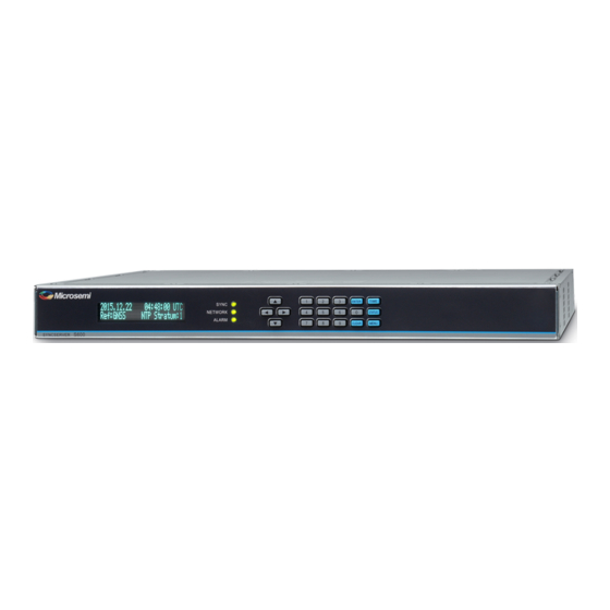
Physical Description Figure 1-1. SyncServer S600 Front Panel Figure 1-2. SyncServer S600 Rear Panel - Single AC Version Figure 1-3. SyncServer S650 Rear Panel - Single AC Version with 10 GbE Figure 1-4. SyncServer S600 Rear Panel - Dual AC Version 098-00720-000 Revision D1 –... -
Page 32: Syncserver S600 Rear Panel - Dual Ac Version With 10 Gbe
Chapter 1 Overview Physical Description Figure 1-5. SyncServer S600 Rear Panel - Dual AC Version with 10 GbE Figure 1-6. SyncServer S600 Rear Panel - Dual DC Version Figure 1-7. SyncServer S600 Rear Panel - Dual DC Version with 10GbE SyncServer 600 Series User’s Guide... -
Page 33: Syncserver S650 Rear Panel - Single Ac Version With 10 Gbe
Chapter 1 Overview Physical Description Figure 1-8. SyncServer S650 Front Panel Figure 1-9. SyncServer S650 Rear Panel - Single AC Version Figure 1-10. SyncServer S650 Rear Panel - Single AC Version with 10 GbE Figure 1-11. SyncServer S650 Rear Panel - Dual AC Version 098-00720-000 Revision D1 –... -
Page 34: Syncserver S650 Rear Panel - Dual Ac Version With 10Gbe
Chapter 1 Overview Physical Description Figure 1-12. SyncServer S650 Rear Panel - Dual AC Version with 10GbE Figure 1-13. SyncServer S650 Rear Panel - Dual DC Version Figure 1-14. SyncServer S650 Rear Panel - Dual DC Version with 10 GbE Figure 1-15. -
Page 35: Communications Connections
Chapter 1 Overview Physical Description Figure 1-16. SyncServer S650i Rear Panel - Single AC Version Figure 1-17. SyncServer S650i Rear Panel - Dual AC Version Communications Connections The SyncServer S6x0 is primarily controlled through the web interface available on LAN 1. Limited functionality is available via the console serial port. Ethernet Management Port - LAN1 Ethernet port 1 is the management port that is used to access the web interface. -
Page 36: Input Connections
GNSS Connection The SyncServer S6x0 features a BNC connector for input from GNSS navigation satellites to provide a frequency and time reference. This port also provides 9.7V tothe power a Microsemi GNSS antenna (see Antenna Kits Overview Appendix C, Installing GNSS Antennas). -
Page 37: Output Connections
The dedicated Data/Timing port is provided to output NMEA-0183 or NENA PSAP strings. If NENA is selected, the serial Console port also supports the two-way timing aspects of the standard. In addition, the F8 and F9 Microsemi legacy time strings are available. -
Page 38: Alarm Relay
Chapter 1 Overview Physical Description Alarm Relay The SyncServer S6x0 features a Phoenix connector for an alarm relay output. See Figure 1-24. The relay is open when the configured alarm classes (Figure 1-25) occur. If the SyncServer S6x0 is not powered, then the alarm relay will be open. The relay is energized (shorted), when the SyncServer S6x0 is powered and no configured alarms are active. -
Page 39: Low Phase Noise (Lpn) Module Connections
Chapter 1 Overview Physical Description Figure 1-27 to view the signal types for the standard configuration and the configuration with the FlexPort™ option. Figure 1-26. Timing I/O Module BNC Connectors Figure 1-27. Signal Types for Timing I/O Module Low Phase Noise (LPN) Module Connections The module has eight 10MHz LPN outputs (J1-J8). -
Page 40: Power And Ground Connections
Chapter 1 Overview Physical Description Figure 1-28. LPN Module Connections Figure 1-29. LPN Module Signal Types Power and Ground Connections The SyncServer S6x0 is available with either single or dual 120/240 VAC power, or dual DC power. The SyncServer S6x0 is not equipped with a Power switch. AC power is controlled by the unplugging the AC power cord. -
Page 41: Functional Description
Chapter 1 Overview Functional Description Figure 1-30. SyncServer S6x0 Single AC Version Power and Ground Figure 1-31. SyncServer S6x0 Dual AC Version Power and Ground Figure 1-32. SyncServer S6x0 Dual DC Version Power and Ground Functional Description 098-00720-000 Revision D1 – February, 2018 SyncServer 600 Series User’s Guide... -
Page 42: Leds
Chapter 1 Overview Functional Description LEDs The SyncServer S6x0 provides three LEDs on the front panel, as shown in Figure 1-33, that indicate the following: Sync Status Network Status Alarm Status Figure 1-33. LEDs for SyncServer S3x0 Figure 2-6 for details about the LEDs. -
Page 43: Time Inputs
Chapter 1 Overview Functional Description Time Inputs The SyncServer S6x0 can use GNSS, NTP, and IRIG as external input references (depending on model and configuration). The NTP signals use the RJ45 (1 - 4) connectors on the rear panel. The GNSS reference uses a BNC connector on the rear panel. -
Page 44: Configuration Management
Chapter 1 Overview Configuration Management Note: The SyncServer S6x0 uses IRIG 1344 version C37.118.1a-2014. On the input side, the code performs a subtraction using control bits 14 - 19 from the supplied IRIG time with the expectation that this will produce UTC time. This aligns with the C37.118.1a-2014 definition. -
Page 45: Command Line Interface (Cli)
Chapter 1 Overview Alarms Figure 1-34. Web Interface - Dashboard Command Line Interface (CLI) The Command Line Interface can be used to control specific function of the SyncServer S6x0 from a terminal connected to the EIA-232 serial port or the Ethernet LAN1 port. - Page 46 Chapter 1 Overview Alarms SyncServer 600 Series User’s Guide 098-00720-000 Revision D1 – February, 2018...
-
Page 47: Chapter 2 Installing
Chapter 2 Installing This chapter describes the procedures for installing the SyncServer S6x0. In This Chapter Getting Started Unpacking the Unit Rack Mounting the SyncServer S6x0 Installation Check List Signal Connections – Communications Connections – SyncServer S6x0 Synchronization and Timing Connections Connecting the GNSS Antenna ... -
Page 48: Getting Started
Getting Started Getting Started Before you begin to install the SyncServer S6x0, review the information in this section. If you encounter any difficulties during the installation process, contact Microsemi Frequency and Time Division (FTD) Services and Support. See Contacting Technical Support, on page 248 for telephone numbers. -
Page 49: Installation Tools And Equipment
1. Wear a properly grounded protective wrist strap or other ESD device. 2. Inspect the container for signs of damage. If the container appears to be damaged, notify both the carrier and your Microsemi distributor. Retain the shipping container and packing material for the carrier to inspect. -
Page 50: Rack Mounting The Syncserver S6X0
See Figure 2-1 for the location of the label on the SyncServer S6x0. Contact your Microsemi distributor if the model or item number do not match. For a complete listing of item numbers, see... -
Page 51: Dimensions For Syncserver S6X0
Chapter 2 Installing Rack Mounting the SyncServer S6x0 Figure 2-2. Dimensions for SyncServer S6x0 Figure 2-3. Rack Mounting the SyncServer S6x0 098-00720-000 Revision D1 – February, 2018 SyncServer 600 Series User’s Guide... -
Page 52: Making Ground And Power Connections
SyncServer S6x0, as shown in Figure 2-4 Figure 2-5. Figure 2-4. SyncServer S600/S650 Power & Ground Connections - Single AC Version Figure 2-5. SyncServer S600/S650 Power & Ground Connections - Dual AC Version Figure 2-6. Universal Ground Symbol After installing the SyncServer S6x0 into the rack, connect the chassis to the proper grounding zone or master ground bar per local building codes for grounding. - Page 53 Ground on the rack. The rack grounding method is below. Recommendation: Although there are a number of methods for connecting the equipment to earth ground, Microsemi recommends running a cable of the shortest possible length from the ground lug to earth ground.
-
Page 54: Ac Power Connection
Chapter 2 Installing Making Ground and Power Connections AC Power Connection Use the following procedure to make the power connections for the AC version of the SyncServer S6x0. An Over-Current Protection Device must be placed in front of the shelf power. Figure 2-7. -
Page 55: Signal Connections
Chapter 2 Installing Signal Connections Warning: To avoid possible damage to equipment, you must provide power source protective fusing as part of the installation. The SyncServer S6x0 is intended for installation in a restricted-access location. 1. Create a custom cable using the supplied Molex connector housing and terminals. -
Page 56: Serial Port Male Mating Connector Pins
Chapter 2 Installing Signal Connections Ethernet Port 1 Ethernet port 1 is a standard 100/1000 Base-T shielded RJ-45 receptacle on the rear panel of the unit. It is used to provide connectivity to a web interface and to an Ethernet local area network (as well as for NTP input/output). To connect the SyncServer S6x0 to an Ethernet network, use an Ethernet RJ-45 cable. -
Page 57: Syncserver S6X0 Synchronization And Timing Connections
Chapter 2 Installing Signal Connections SyncServer S6x0 Synchronization and Timing Connections The SyncServer S6x0 has one GNSS input and four NTP input/output connections. The SyncServer S6x0 has one 1PPS output. The SyncServer S650 may also have an optional Timing I/O Module. GNSS Connection To connect a GNSS signal to the SyncServer S6x0, you must install a GPS antenna. -
Page 58: 10 Gbe Connections
Chapter 2 Installing Signal Connections Figure 2-12. Ethernet Connections 10 GbE Connections The two SFP+ ports are only available with the 10 GbE option. These SFP+ ports are equipped with hardware timestamping that supports NTP, PTP, and NTP Reflector operations. These ports are ideal for interoperability with 10 GbE switches. -
Page 59: Timing I/O Module Connections
Chapter 2 Installing Signal Connections Table 2-3. Recommended and Supported SFP+ (10GbE) Transceivers Vendor Mode Item Code or P/N Cisco single mode SFP-10G-LR Juniper multi-mode SFPP-10G-SR Juniper single mode SFPP-10G-LR Juniper multi-mode EX-SFP-10G-SR Juniper single mode EX-SFP-10G-LR Timing I/O Module Connections The standard configuration offers a broad yet fixed selection of signal I/O on its eight BNC connectors (see Figure... -
Page 60: Lpn Module Connections
Chapter 2 Installing Signal Connections LPN Module Connections This module provides low phase noise 10 MHz signals on all eight ports (J1-J8). Figure 2-15. Figure 2-15. LPN BNC Connections Serial Timing Connection The SyncServer S6x0 features a DB-9 female connector on the rear panel of the unit. -
Page 61: Connecting The Gnss Antenna
Chapter 2 Installing Connecting the GNSS Antenna 1PPS Output Connection The SyncServer S6x0 features a single BNC female connector for the 1PPS signal. Figure 2-17. Figure 2-17. 1PPS Output Connection Connecting the GNSS Antenna Caution: The GNSS cables should only be connected while the unit is properly earth grounded. -
Page 62: Connecting Alarm Relay
Chapter 2 Installing Connecting Alarm Relay Warning: To avoid serious personal injury or death, exercise caution when working near high voltage lines. In particular: Use extreme caution when installing the antenna near, under, or around high voltage lines. Follow local building electrical codes for grounding the chassis. ... -
Page 63: Applying Power To The Syncserver S6X0
Chapter 2 Installing Applying Power to the SyncServer S6x0 Applying Power to the SyncServer S6x0 The SyncServer S6x0 is not equipped with a Power switch. After installing the unit in a rack and making the necessary connections described in previous sections, turn on power at the distribution panel. - Page 64 Chapter 2 Installing Applying Power to the SyncServer S6x0 SyncServer 600 Series User’s Guide 098-00720-000 Revision D1 – February, 2018...
-
Page 65: Chapter 3 Keypad / Display Interface
Chapter 3 Keypad / Display Interface This chapter describes the keypad / display interface. Overview The keypad / display interface displays the time, system status, and provides the following functions: Configuring and enabling/disabling the LAN1 network port. Setting the time and entering freerun mode. ... -
Page 66: Time Button
Chapter 3 TIME Button TIME Button Cycling the TIME button changes the predefined format and contents of the time display: Large numeric time display on full screen. Hours:Minutes:Seconds Medium numeric time display on the left, current reference and NTP Stratum on the right Small date and time, reference, and NTP stratum. -
Page 67: Ntp Status Screen
Chapter 3 STATUS Button Figure 3-1. NTP Status Screen Some screens have a "Next>" in the upper right. This means more information is available by pressing the right arrow button. This cycles through screens on that topic. NTP Status Screen Network Time Protocol (NTP) status. -
Page 68: Clock Status Screen
Chapter 3 STATUS Button State: Shows “Up” if the port is enabled and “Down” if the port is disabled. IP: IP address for the port SM: Subnet mask GW: Gateway address Clock Status Screen Hardware Clock and Input Reference status. GNSS Receiver Status Screen GNSS receiver status. -
Page 69: Menu Button
Chapter 3 MENU Button Option: Description of installed module (if any) Flex I/O Option: Enabled | Disabled J1 Input: Configuration of input J2: Input: Configuration of input J3 Output: Configuration of output J4 Output: Configuration of output J5 Output: Configuration of output J6 Output: Configuration of output J7 Output: Configuration of output J8 Output:Configuration of output... -
Page 70: Display
Chapter 3 MENU Button 2. On/Off: Use On to enable the LAN1 network port. Off disables the LAN1 network port for all traffic types. Figure 3-4. Select LAN1 IP Mode Screen 1. IPv4: Select IPv4address mode for LAN1 port. If IPv4 is selected, the Select Addressing Type screen will appear, as shown in Figure 3-5. -
Page 71: Sys Control
Chapter 3 MENU Button Figure 3-7. Display Menu Screen 1. Set Time: Enter the UTC date and time using 24-hour format. Select OK to apply the entered time to the Hardware Clock and not use external time references. Figure 3-8. Figure 3-8. -
Page 72: Keypad
Chapter 3 MENU Button Figure 3-11. Shutdown / Factory Default Screen Factory Defaults in Appendix B for default settings. 1. Shutdown: Halts the SyncServer. The message Press the ENTER button to Confirm appears in the display, as shown in Figure 3-12. -
Page 73: Chapter 4 Web Interface
The user is locked out for 1 hour. The lockout is also removed if the unit is rebooted. Note: The default user name is “admin” and the default password is: Microsemi . To avoid unauthorized access, you should change the default password. -
Page 74: System Information
Depending on the browser used, the web page responsiveness will vary due to the use of the encryption cipher suite used in the S6x0. Microsemi recommends using the Google Chrome browser. System Information The System information window in the Dashboard, as shown in... -
Page 75: Status / Information Windows
Chapter 4 Status / Information Windows Figure 4-3. System Status Status / Information Windows The Status/Information windows in the dashboard, as shown in Figure 4-4, displays status details and information regarding the following: Timing GNSS Network Timing Services ... -
Page 76: Timing Status & Information
Chapter 4 Status / Information Windows Figure 4-4. Status/Information Windows Timing Status & Information The Timing window in the dashboard, as shown in Figure 4-5, displays status details and information about system timing, including current reference, lock status, and status of input references. See Table 4-1. -
Page 77: Timing Window Descriptions
Chapter 4 Status / Information Windows The SyncServer 6x0 does not contain a battery-backed Note: real time clock. Therefore, it will always boot up with a default value for the system time. This time will be updated when it obtains time from a time reference such as GNSS, IRIG, or NTP. - Page 78 If there is a warning of a Leap second pending it will be red. The SyncServer S600/S650 has separate timing and frequency clock controls. The time and frequency clocks are usually in the same clock state. If they are different, then the “Current Reference”...
-
Page 79: Status - Clock State Descriptions
Chapter 4 Status / Information Windows Table 4-2. Status - Clock State Descriptions Status Indication Meaning Details Warmup SyncServer not ready for any type of Directly equal to the common synchronization functionality. This is a warmup clock state (to both freq one-time status following power-up and time) Freerun... - Page 80 Chapter 4 Status / Information Windows Table 4-2. Status - Clock State Descriptions (Continued) Status Indication Meaning Details Holdover Same as prior row but specific additional The unit has been in holdover conditions are met. for more than a user-specified duration and the holdover is This condition occurs if the current based on the SyncServer...
-
Page 81: Status - Current Source Details
Chapter 4 Status / Information Windows Table 4-3. Status - Current Source Details Status Where it Will Item Details Happen No current source Warmup Directly equal to the common warmup clock state (to both freq and time) Current Source taken Locking When the status is any of these there from Timing... -
Page 82: Gnss Status & Information
Chapter 4 Status / Information Windows GNSS Status & Information The GNSS window in the dashboard, as shown in Figure 4-6, displays status details and information about GNSS. C/No is the carrier-to-noise density which is defined as the carrier power divided by the noise power spectral density. Higher C/No results in better tracking and performance. -
Page 83: Network Status & Information
Chapter 4 Status / Information Windows Table 4-4. GNSS Window - Descriptions Field Potential Values Notes Position Status No Data - no position data Survey 2D - calculated 2D position, lat/lon but no elevation Survey - calculating position and ... -
Page 84: Ntp Status & Information
Chapter 4 Status / Information Windows NTP Status & Information The NTP window in the dashboard, as shown in Figure 4-8, displays status details and information about the NTP configuration. Figure 4-8. NTP Window Note: The dashboard will provide Leap indicator information as soon as it is available. -
Page 85: Alarm Information
Chapter 4 Status / Information Windows Figure 4-10. Timing Services Status Window Alarm Information The Alarms window in the dashboard, as shown in Figure 4-11, displays active alarms. Figure 4-11. Alarms Window Slot Modules Status & Information The Slot Modules window in the dashboard, as shown in Figure 4-12, displays status details about the modules installed in the Options Slots. -
Page 86: Navigation Windows
Admin->General page. Note: You can check for the latest version number of SyncServer S600 and S650 software at these URLs: http://update.microsemi.com/SyncServer_S600 http://update.microsemi.com/SyncServer_S650 The number of the most current version of the software will appear. -
Page 87: Navigation Portion Of Dashboard
Chapter 4 Navigation Windows Figure 4-14. Navigation Portion of Dashboard 098-00720-000 Revision D1 – February, 2018 SyncServer 600 Series User’s Guide... -
Page 88: Network Configuration Windows
Chapter 4 Navigation Windows Network Configuration Windows The Network tab on the dashboard provides access to windows for Ethernet, SNMP, SNMP Trap configuration, and Ping. Network - Ethernet Configuration Use this window to configure or modify the Ethernet setting for LAN1 - LAN6, and to manually set the DNS server address for LAN1. -
Page 89: Network - Ethernet Configuration Window
Chapter 4 Navigation Windows Figure 4-15. Network - Ethernet Configuration Window Network - SNMP Configuration Use this window to add, edit or delete v2 communities, and to add or delete SNMP users. See Figure 4-16. The following SNMP parameters can be configured: Basic Configuration ... -
Page 90: Network - Snmp Window
Chapter 4 Navigation Windows The SNMP engine ID is displayed for the user's convenience. The SNMP MIB files for use with the SyncServer can be downloaded on this page. Figure 4-16. Network - SNMP Window Network - SNMP Trap Configuration Use this window add or edit SNMP trap recipients The following parameters can be configured: IP Address - up to 10 trap managers can be added... -
Page 91: Network - Snmp Traps
Chapter 4 Navigation Windows Figure 4-17. Note: Some SNMP browsers and trap managers require that an SNMPv3 user be created with the same username and authentication as used for the trap configuration in order for the SNMPv3 discovery process to complete properly. Note: SNMP is designed to be used with LAN1. -
Page 92: Network - Ping Window
Chapter 4 Navigation Windows Network - Ping Use this window to perform network ping tests. Use ping to test network connectivity out the LAN ports as needed. The result of the ping will be displayed in the window when completed. An IPv4 or IPv6 address should be entered in the IP address field. Figure 4-18. -
Page 93: Network Timing Windows
Chapter 4 Navigation Windows Network Timing Windows The Network Timing tab on the dashboard provides access to windows to configure NTP, view NTP Daemon Status and Control, and to view NTP Associations. NTP SysInfo Window Use this window to view NTP Daemon Status and Control. Figure 4-19. -
Page 94: Ntpd Sysinfo Parameter Descriptions
Chapter 4 Navigation Windows Table 4-5. NTPd SysInfo Parameter Descriptions Parameter Description System Peer The IP address of the clock source. The source is selected by the NTP daemon that is most likely to provide the best timing information based on: stratum, distance, dispersion and confidence interval. - Page 95 Chapter 4 Navigation Windows Table 4-5. NTPd SysInfo Parameter Descriptions (Continued) Parameter Description Leap Indicator The Leap Indicator (LI) is a two-bit binary number in the NTP packet header that provides the following information: Advance warning that a leap second adjustment will be made to the UTC ...
- Page 96 Chapter 4 Navigation Windows Table 4-5. NTPd SysInfo Parameter Descriptions (Continued) Parameter Description Root Delay This is a measure of the total round trip delay to the root of the synchronization tree. A typical value for a SyncServer operating at stratum 1 would be 0 since the SyncServer is a root of the synchronization tree For other stratum levels, an appropriate value is displayed.
-
Page 97: Ntpd Associations Window
Chapter 4 Navigation Windows Figure 4-20. See Table 4-6for descriptions of NTPd Associations parameters. Figure 4-20. NTPd Associations Window 098-00720-000 Revision D1 – February, 2018 SyncServer 600 Series User’s Guide... -
Page 98: Ntpd Associations Parameters
Chapter 4 Navigation Windows Table 4-6. NTPd Associations Parameters Parameter Description Remote The domain name or IP address of the remote end of the NTP association. "Hardware Clock" is the SyncServer's Hardware Clock. In the case of a remote NTP connection, this will be the IP address of the remote end. The character in the left margin indicates the mode in which this peer entry is operating: (space) reject... - Page 99 Chapter 4 Navigation Windows Table 4-6. NTPd Associations Parameters (Continued) Parameter Description Ref Id This is a four-byte field used to identify the reference clock source. At initialization, while the stratum is 16, this field shows the progression of the NTP clock PLL.
- Page 100 Chapter 4 Navigation Windows Table 4-6. NTPd Associations Parameters (Continued) Parameter Description Disp (ms) Dispersion represents the maximum error of the SyncServer relative to the NTP association.There are two components in dispersion, those determined by the peer relative to the primary reference source of standard time and those measured by the SyncServer relative to the peer.
-
Page 101: Ntp Configuration Window
Chapter 4 Navigation Windows NTP Configuration Window Use this window to configure NTP parameters, including the Role (Server, Peer, or Broadcast), Address, and Port. Figure 4-21. See Table 4-5 for descriptions of NTP Configuration parameters. Figure 4-21. NTP Configuration Window Click the Save button after making changes to save the changes. -
Page 102: Ntpd Association Configuration Parameters
Chapter 4 Navigation Windows Table 4-7. NTPd Association Configuration Parameters Parameter Description Role Server Creates a persistent association between the SyncServer (client) and an NTP node (server). The client synchronizes with the server if the client's clock selection algorithm selects this server as the best clock. Typical server associations include: the hardware clock, the factory default NTP servers, and servers added by the user. - Page 103 NTP server to be preferred over the internal hardware reference clock. By default the SyncServer S600 Series has the NTP Prefer selected for the local hardware reference clock. In most operating scenarios the local hardware reference clock (which more often than not will be tracking GNSS) will be the only reference being used.
- Page 104 Chapter 4 Navigation Windows For broadcast, the IP address is the local subnet broadcast address. For multicast, the IP address is an IPv4 or IPv6 multicast address. This can beeither the IANA designated NTP multicast address (224.0.1.1 IPv4 or FF0X:0:0:0:0:0:0:101 IPv6) or any unassigned multicast address (typically in the range 224.0.1.0 to 238.255.255.255 for IPv4 or FF0X:x:x:x:x:x:x:x for IPv6).
-
Page 105: Ntp / Ptp Service Configuration Window
Chapter 4 Navigation Windows NTP / PTP Services Configuration Window Use this window to configure NTP reflector and PTP services. See Figure 4-22. This page can be used to configure multiple NTPr and PTP configurations. However, only one timing service can be mapped to each port. Figure 4-22. - Page 106 Chapter 4 Navigation Windows Table 4-8. NTP / PTP Services Configuration Parameters (Continued) Parameter / Column Description Profile When appropriate, this column is used to further refine the categorization of the timing service. A good example of this in 2.1 release is a PTP master (top-level service), which always operates with a specific PTP profile.
-
Page 107: Ntp Packet Reflector
Chapter 4 Navigation Windows The SyncServer S6x0 Series implements real-time, hardware-based network packet processing in tandem with accurate hardware based NTP/PTP time stamping, general packet limiting and alarming. The reflector protects the SyncServer CPU from excessive network traffic Denial of Service (DoS) attacks, while concurrently providing high-bandwidth, high-accuracy NTP/PTP operations. -
Page 108: Ntp Reflector Vs. Ntp Daemon Performance Trade-Offs
Chapter 4 Navigation Windows Table 4-9. NTP Reflector vs. NTP Daemon Performance Trade-Offs Feature NTP Reflector NTP Daemon Enhanced Security 360,000 NTP requests/second Enhanced Time Stamp Accuracy DoS Detection/Alarming CPU Protection NTP Peering, Clustering, Selection MD5 and Autokey Functions It is important to note that NTP is UDP/IP and is by nature susceptible to DoS attacks as no TCP/IP connection is required. -
Page 109: Ptp Configuration Parameters
Chapter 4 Navigation Windows Figure 4-24. PTP Configuration Parameters NTP / PTP Mapping Window Use this window to map either a NTP reflector or a PTP service to a LAN port. See Figure 4-25. A license is required for all timing services, other than NTPd. NTP reflector requires security license. -
Page 110: Ntpr / Ptp Status Window
Chapter 4 Navigation Windows Figure 4-26. NTPr / PTP Status Window Figure 4-27. NTPr/PTP Status Window - Port Details 110 SyncServer 600 Series User’s Guide 098-00720-000 Revision D1 – February, 2018... -
Page 111: Timing Configuration Windows
Chapter 4 Navigation Windows Timing Configuration Windows The Timing tab on the dashboard provides access to windows to enable time and holdover sources, manually set time, set the time zone, and to configure format of the serial output. Note: The SyncServer 6x0 does not contain a battery-backed real time clock. -
Page 112: Timing - Input Control Window - Upper Portion
Chapter 4 Navigation Windows It is recommended that the SyncServer S6x0 be rebooted when leaving manual time mode. Figure 4-28 Figure 4-29. Figure 4-28. Timing - Input Control Window - Upper Portion Figure 4-29. Timing - Input Control Window - Lower Portion 112 SyncServer 600 Series User’s Guide 098-00720-000 Revision D1 –... -
Page 113: Timing - Holdover Window
Chapter 4 Navigation Windows Timing - Holdover Configuration Window Use this window to configure a duration in holdover (loss of stratum 0 reference) until the server either unlocks or attempts to get time from other NTP servers (if configured to do so). After this holdover period is exceeded, then the unit will attempt to lock to external NTP servers. -
Page 114: 1Pps Time Interval Measurement
Chapter 4 Navigation Windows Figure 4-31. Timing - Time Zone Window Timing - Serial Output Configuration Window This window is used to select the format for the serial timing output for the SyncServer S6x0. See Figure 4-32 below. Figure 4-32. Timing - Serial Output Window 1PPS Time Interval Measurement Requirements Software license... - Page 115 UTC timescale in a format of year-month-day, hours:minutes:seconds.. Example: 2017-10-30,17:57:35,-1.30000000e-07 Microsemi's TimeMonitor Analyzer application can be used to analyze the results. Either download the results, or capture results to a file from the serial port or IP port streams.
-
Page 116: References Configuration Window
Chapter 4 Navigation Windows Note: The 1PPS input should be disabled on the Timing->Input control page. The measurement is not useful if the SyncServer is using the 1PPS as the reference. Note: Measurements are not useful if the SyncServer system clock has not been set or is changing. -
Page 117: References - Status Window
The Position Mode allows the user to set the position mode to Survey (stationary), Position Hold (stationary), or Dynamic. The default configuration for the SyncServer S6x0 is Survey mode. For stationary applications, Microsemi recommends using the Survey mode to avoid timing errors introduced by manually entering an inaccurate position. -
Page 118: Security Configuration Windows
Chapter 4 Navigation Windows Position Hold allows the user to manually enter the position for a stationary application. The user enters the Latitude, Longitude and Altitude values for the SyncServer S6x0. The position needs to be accurately determined to avoid creating timing errors. - Page 119 Chapter 4 Navigation Windows Security - Users Window Use this window to add or delete users, and for Password Maintenance. See Figure 4-36. All Users and Admin have the same privileges Note: Only alphanumeric characters and underline are allowed for the User name.
-
Page 120: Security - Users Configuration Window
Chapter 4 Navigation Windows Figure 4-36. Security - Users Configuration Window Security - Access Control Configuration Window Use this window to configure access control for LAN1-LAN6 (whitelist). If nothing is configured, then the unit will accept data from all devices. If any addresses are configured, only packets from those devices will be accepted. -
Page 121: Security - Services & System Control Configuration Window
Chapter 4 Navigation Windows Security - Services & System Control Window Use this window to configure the state for the Webserver, NTP, SNMP, SSH, and TOD, and to reboot or halt the system. See Figure 4-38. Figure 4-38. Security - Services & System Control Configuration Window Security - HTTPS Configuration Window Use this window to configure the web server and self-signed certificate info. -
Page 122: Security - Https Configuration Window
Note: The https certificate will revert to self-signed certificate after importing configuration. Table 4-10. Supported HTTPS Protocols Model TLS 1.0 TLS 1.1 TLS 1.2 SyncServer S600 SyncServer S650 122 SyncServer 600 Series User’s Guide 098-00720-000 Revision D1 – February, 2018... -
Page 123: Https Configuration Parameters
Chapter 4 Navigation Windows Table 4-11. HTTPS Configuration Parameters Parameter / Column Description Protocols TLS 1.1 or TLS 1.2 Cipher Suites SSL high or SSH high and medium Web Session Timeout Timeout range from 5 to 1440 minutes Table 4-12. HTTPS Self-Signed Certificate Parameters Parameter / Column Description Bits... -
Page 124: Security - Ssh Configuration Window
Chapter 4 Navigation Windows Security - SSH Configuration Window Use this window to configure SSH security. See Figure 4-40. Including the same username in both the allowed and denied lists is not supported. Figure 4-40. Security - SSH Configuration Window Security - NTPd Symmetric Keys Configuration Window Use this window to generate, upload and download NTP Symmetric Security Keys. -
Page 125: Security - Ntpd Autokey Server Configuration Window
Chapter 4 Navigation Windows Figure 4-42. Security - NTPd Autokey Server Configuration Window Security - NTPd Autokey Client Configuration Window Use this window to configure the NTP Autokey Client and install the IFF Group Key file. See Figure 4-43. Figure 4-43. Security - NTPd Autokey Client Configuration Window Security - RADIUS Configuration Window Use this window to enable and configure RADIUS authentication. -
Page 126: Security - Radius Configuration Window
Note: RADIUS key: 1-16 characters Note: The SyncServer S600/S650 has only one level of management access of Authentication/Authorization and that is full control. There is no read-only management access. Therefore Authentication = Authorization when there is only one level of management access. -
Page 127: Security - Tacacs+ Configuration Window
TACACS+ server address in a subnet used by the other LAN ports (LAN2 - LAN6). Figure 4-45. Security - TACACS+ Configuration Window Note: The SyncServer S600/S650 has only one level of management access of Authentication/Authorization and that is full control. There is no read-only management access. Therefore Authentication = Authorization when there is only one level of management access. - Page 128 Chapter 4 Navigation Windows Security - LDAP Configuration Window Use this window to enable LDAP, and configure LDAP settings and servers. Up to 5 LDAP servers can be configured.See Figure 4-46. The SyncServer S6xx software supports remote authentication using RADIUS, TACACS+ and LDAP servers.
-
Page 129: Security - Ldap Configuration Window
Chapter 4 Navigation Windows Figure 4-46. Security - LDAP Configuration Window Note: The SyncServer S600/S650 has only one level of management access of Authentication/Authorization and that is full control. There is no read-only management access. Therefore Authentication = Authorization when there is only one level of management access. - Page 130 Chapter 4 Navigation Windows Table 4-13. LDAP Configuration Parameters (Continued) Parameter / Column Description Scope to search with base - limits search to base object one - limits search to immediate children of base object, but not base object sub - search base objects and all child objects ...
-
Page 131: Security - Packet Monitoring Window
Chapter 4 Navigation Windows Security - Packet Monitoring (security license required) Use this window to configure packet load monitoring thresholds. The All Packets threshold is used to limit the number of packets from each port that are sent to the processor. -
Page 132: Security - X.509 Csr Window
Chapter 4 Navigation Windows The SyncServer is typically deployed within an enterprise that manages it's own root and/or intermediate Certification Authorities. The Certificate Signing Requests generated by the SyncServer will be signed by these internal Certification Authorities to generate X.509 Certificates that will be installed on the SyncServer. The CSR page accepts the following information from the user: Figure 4-48. - Page 133 Chapter 4 Navigation Windows Security - X.509 Install Use this window to install on the SyncServer the Certificate or Certificate/Chain that was generated using the CSR. See Figure 4-49 Installation can be done with certificate/chain files in PEM or PKCS7 format. The PEM format is the most common format that Certification Authorities issue certificates in.
-
Page 134: Admin Configuration Windows
Figure 4-50. Enables the SyncServer to check the Microsemi upgrade notification site at http://update.microsemi.com every day at noon local time for new software updates. Displays a notice on the Status page and can send and SNMP trap when an upgrade is available. Requires that the SyncServer management port have firewall access to the internet. -
Page 135: Admin - General Configuration Window
Chapter 4 Navigation Windows Figure 4-50. Admin - General Configuration Window Note: The software update availability feature uses IPv4. An IPv4 address and DNS server must be configured on the Network->Ethernet page in order to use this feature. Admin - Alarm Relay Configuration Window Use this window to configure system alarm relay details. -
Page 136: Admin - Alarm Configuration Window
Chapter 4 Navigation Windows Figure 4-52. Admin - Alarm Configuration Window Table 4-15. Alarm Configuration Parameter Descriptions Parameter Description Name Name of the alarm. If there is an asterisk as first character it means it is a transient alarm. For alarms that have multiple secondary info (e.g. Excessive Traffic on Ethernet port has a secondary field that identifies which port), these settings are global to all of the secondary cases. -
Page 137: Admin - Email Configuration Window
Chapter 4 Navigation Windows Table 4-15. Alarm Configuration Parameter Descriptions (Continued) Parameter Description Auto ACK This is the same as Clear Now except it provides an automatic clearing action after a user-defined time period following SET of the alarm. Zero (default) means to never auto-clear it. Severity Controls the reported severity level of the alarm. -
Page 138: Admin - Banner Configuration Window
Chapter 4 Navigation Windows Admin - Banner Configuration Window Use this window to enable whether the login banner is displayed before the login interface. Users can create a custom banner or use a standard U.S. government banner. See Figure 4-54. Figure 4-54. -
Page 139: Admin - Serial Port Configuration Window
Chapter 4 Navigation Windows Admin - Serial Port Configuration Window Use this window to configure the parameters for the Time of Day port and for the console Serial port. See Figure 4-55. Figure 4-55. Admin - Serial Port Configuration Window Admin - Upgrade System Software Window Use this window to upgrade system software. - Page 140 SyncServer unit is authorized to upgrade with the specified upgrade file. Note: You can check for the latest version number of SyncServer S600 and S650 software at these URLs: http://update.microsemi.com/SyncServer_S600 http://update.microsemi.com/SyncServer_S650 The number of the most current version of the software will appear.
-
Page 141: Admin - Options Configuration Window
Chapter 4 Navigation Windows Admin - Options Configuration Window Use this window to enter option keys to enable SyncServer options. See Figure 4-57. Figure 4-57. Admin - Options Configuration Window Admin - Configuration Backup / Restore / Reset Use this window to back up, restore, or reset the SyncServer S6x0 to factory configuration. -
Page 142: Logs Configuration Windows
Chapter 4 Navigation Windows Logs Configuration Windows Logs - System Log Configuration Window Use this window to set, modify, or delete IP addresses / DNS names of remote systems to which to send log information. See Figure 4-59. Note: Syslog is designed to be used with LAN1. Do not configure a system log server address in a subnet used by the other LAN ports (LAN2 - LAN6). -
Page 143: Logs - Events Window
Chapter 4 Navigation Windows Figure 4-60. Logs - Events Window 098-00720-000 Revision D1 – February, 2018 SyncServer 600 Series User’s Guide 143... -
Page 144: Option Slot A/ Slot B Configuration Windows
Chapter 4 Navigation Windows Logs - Messages Window Use this window to view and save the message log. Most recent entries appear at the end of the display (scroll to the end). See Figure 4-61. Figure 4-61. Logs - Messages Window Option Slot A/ Slot B Configuration Windows Options Slot A Configuration Window - Timing I/O Module Use this window to configure the module in Options Slot A. -
Page 145: Options Slot A Configuration Window Showing Timing I/O Module
Navigation Windows Figure 4-62. Options Slot A Configuration Window Showing Timing I/O Module The SyncServer S600/S650 has separate timing and frequency clock controls. The squelch feature uses the time clock state for timecode and fixed-rate pulse modes. The squelch feature uses the frequency clock state for programmable-period pulse and sine modes. - Page 146 Chapter 4 Navigation Windows Table 4-16. Squelch Settings Squelch Setting Function Notes In warmup / freerun Prevent output from powerup Output will be turned on when until the unit comes out of “Locking” is entered. freerun. Once (if) it does it will stay on since these states can never be re-entered.
- Page 147 Chapter 4 Navigation Windows Table 4-17. Clock Status (Continued) Conditions Required SyncServer Possible Next Description for Next Transition Clock Status State State Fast-track The selected input has been Freerun The unit no longer has a qualified and the firmware qualified input. clock servo begins to actively Normal Clock stabilized...
-
Page 148: Help Windows
Chapter 4 Navigation Windows Options Slot B Configuration Window - Low Phase Noise (LPN) Module Use this window to configure the module in Options Slot A. The example shown in Figure 4-63 is for the Low Phase Noise (LPN) module. Note: Option Slot B is only available with the SyncServer S650. -
Page 149: Chapter 5 Command Line Interface (Cli)
Chapter 5 Command Line Interface (CLI) This chapter describes the CLI command conventions, the prompts, line editing functions, and command syntax. The CLI command functions and features are listed alphabetically. In This Chapter SyncServer S6x0 CLI Command Set SyncServer S6x0 CLI Command Set This section provides an alphabetical listing and details of all CLI commands. - Page 150 Chapter 5 SyncServer S6x0 CLI Command Set SyncServer S6x0 Table 5-1. CLI Commands for Command Similar Web Interface Location set image Admin > Configuration Backup / Restore / Reset show ip Network > Ethernet set ip Network > Ethernet set nena active Timing >...
-
Page 151: Set Clock
Chapter 5 SyncServer S6x0 CLI Command Set set clock This command provides an ability to set the time. Command Syntax: set clock date-time <date-time> where <date-time> = YYYY-MM-DD,HH:MM:SS The time is presumed to be UTC. 098-00720-000 Revision D1 – February, 2018 SyncServer 600 Series User’s Guide 151... -
Page 152: Set Configuration
Chapter 5 SyncServer S6x0 CLI Command Set set configuration Use this command to replaces the current configuration with the factory default configuration. On SyncServer, user is prompted with “Y” to confirm that they really want to do it. set configuration factory Returning the configuration to factory defaults also includes: Loss of configured user logins ... -
Page 153: F9 - Time On Request
Chapter 5 SyncServer S6x0 CLI Command Set F9 - Time on Request The F9 command is used to record the time the SyncServer S6x0 receives a request from the user. The general behavior is covered in Table 5-2. This function is configurable through the command line interface only. - Page 154 Chapter 5 SyncServer S6x0 CLI Command Set HH=hours. MM=minutes. SS=seconds. mmm=milliseconds. :=colon separator. Q=time quality character, as shown below SPACE = Time error is less than time quality flag 1's threshold . = Time error has exceeded time quality flag 1's threshold * = Time error has exceeded time quality flag 2's threshold # = Time error has exceeded time quality flag 3's threshold ? = Time error has exceeded time quality flag 4's threshold, or a...
-
Page 155: F50 - Gps Receiver Lla/Xyz Position
Chapter 5 SyncServer S6x0 CLI Command Set F50 - GPS Receiver LLA/XYZ Position GPS Receiver LLA/XYZ Position Use function to display the current GPS position, as well as the following: Select the positional coordinate system, Latitude Longitude Altitude (LLA) or XYZ ... - Page 156 Chapter 5 SyncServer S6x0 CLI Command Set F50 B1 LLA<CR> SyncServer S6x0 responds: F50 B1 N 38d23'51.3" W 122d42'53.2" 58m<CR><LF> To display the present antenna position using ECEF XYZ coordinates in meters, use the following format: F50<S>B<N><SEP>XYZ<CR> SyncServer S6x0 responds using the following format: F50B<N><S><SIGN><S><MX>m<S><SIGN><S><MY>m<S><SIGN><MZ>m<CR><...
-
Page 157: F73 - Alarm Status
Chapter 5 SyncServer S6x0 CLI Command Set F73 - Alarm Status Use function F73 to view alarm status. The SyncServer S6x0 will return a response in the follow format: F73<SP>S<STATUS><SOURCE><SP><123456789ABCDEFGHIJ><CR><LF> The alphanumeric characters 1-9 and A-J represent specific positions in the response string shown above. - Page 158 SyncServer S6x0 clock’s hardware PLL has failed. While the PLL indicator is “Unlocked”, all SyncServer S6x0 clock timing parameters are unreliable and should not be used. Contact Microsemi FTD Services and Support. “–” = Locked Always “–” for initial release.
- Page 159 Chapter 5 SyncServer S6x0 CLI Command Set Table 5-3. F73 Alarm Indicators Syntax Alarm Indicators Description IRIG - Slot A “–” = OK Indicates OK when the Slot A-J1 input is qualified for time. This connector “I” = Fault supports all IRIG inputs. This is equivalent to Green ...
- Page 160 Chapter 5 SyncServer S6x0 CLI Command Set Table 5-3. F73 Alarm Indicators Syntax Alarm Indicators Description Secondary Dual AC version This alarm can only be set for the Power version that has Dual AC. “–” = OK “w” = Fault Single AC version “–”...
- Page 161 Chapter 5 SyncServer S6x0 CLI Command Set Table 5-3. F73 Alarm Indicators Syntax Alarm Indicators Description (For future use) “–” = OK Always “–” Carriage return <CR> Line feed <LF> Example: SyncServer> F73 Response: F73 : SLP X---IA-w----------- 098-00720-000 Revision D1 – February, 2018 SyncServer 600 Series User’s Guide 161...
-
Page 162: Show Gnss Status
Chapter 5 SyncServer S6x0 CLI Command Set show gnss status This command provides GPS satellite tracking information: show gnss status Example: SyncServer> show gnss status Response: Gnss Status Latitude : 12 21 06.39 N Longitude : 76 35 05.17 E HGT Val Ellipsoid : 712.4 m HDOP : 0.970000 PDOP : 1.980000... -
Page 163: Halt System
Chapter 5 SyncServer S6x0 CLI Command Set halt system Use this command to shut down the operating system as a preparatory step before power-off. This command does not reboot the system. halt system The behavior of this command is the same as using the Web GUI to perform a Halt (Dashboard>Security>Services). -
Page 164: History
Chapter 5 SyncServer S6x0 CLI Command Set history The command provides a listing of user entries during this session, regardless of their validity. If a configuration command provides the configuration value(s) on the same entry line as the command, then the configuration value(s) will be shown in the history. -
Page 165: Show Image
Chapter 5 SyncServer S6x0 CLI Command Set show image Use this command to display current version in active and backup locations, as well as which image will be used on boot. Command Syntax: show image Example SyncServer> show image Response SYSTEM IMAGE DETAILS Active Image : 1 Backup Image : 2... -
Page 166: Show Ip
Chapter 5 SyncServer S6x0 CLI Command Set show ip Use this command to display the current IP settings for all LAN ports. Command Syntax: show ip config The information displayed is consistent with the content shown in the Web Interface (Dashboard>Network>Ethernet). - Page 167 Chapter 5 SyncServer S6x0 CLI Command Set |..|........|..|........| |LAN3|2001:db9:ac10:fe10::2 |64 |2002:0DB9:AC10:FE10::1 | |..|........|..|........| |LAN4| |0 | | ----------------------------------------------------------------------------- Example 2: SyncServer> show ip status Response 2: Ethernet MAC ------------------------- |Port|MAC |----|------------------| |LAN1|00:B0:AE:00:36:0B | |..|....| |LAN2|00:B0:AE:00:36:0C | |..|....| |LAN3|00:B0:AE:00:36:0D | |..|....| |LAN4|00:B0:AE:00:36:0E | ------------------------- Eth Status-IPv4...
-
Page 168: Set Ip
Chapter 5 SyncServer S6x0 CLI Command Set set ip Use this command to set the address mode to DHCP (IPv4 or IPv6) for the LAN1-LAN6 ports. Use this command to provision the Host, Mask, and Gateway for IPv4 static addresses. Command Syntax: To provision the IPv4 or IPv6 address mode on the specified LAN port as DHCP: ... -
Page 169: Set Nena Active
Chapter 5 SyncServer S6x0 CLI Command Set set nena active Use this command to enable the NENA response mode on this connection. Command Syntax: set nena active Example: SyncServer>set nena active Response: NENA response active: CR to trigger, ctrl-c to deactivate 2016 349 07:40:19 S+00 2016 349 07:40:21 S+00 2016 349 07:40:22 S+00... -
Page 170: Show Nena-Format
Chapter 5 SyncServer S6x0 CLI Command Set show nena-format Use this command to display the current NENA format for the CLI connection. Command Syntax: show nena-format Example: s650>show nena-format Response NENA format : 8 set nena-format Use this command to set the NENA format for the CLI connection. Command Syntax: set nena-format [0|1|8] Example:... -
Page 171: Reboot System
Chapter 5 SyncServer S6x0 CLI Command Set reboot system This command halts current operation, then reboots the SyncServer S6x0. Except for no loss of power, this is functionally equivalent to power-up of the SyncServer S6x0. reboot system The behavior of this command is the same as using the Web GUI to perform a Reboot (Dashboard>Security>Services). -
Page 172: Set Service
Chapter 5 SyncServer S6x0 CLI Command Set set service Use this command to enable or disable HTTP on the SyncServer S6x0. When disabled the Web interface will not be accessible. The only way to re-enable HTTP is using this CLI command. Disabling HTTP provides a method to effectively eliminate the ability to remotely configure SyncServer S6x0. -
Page 173: Set-Session-Timeout
Chapter 5 SyncServer S6x0 CLI Command Set set-session-timeout Use this command to define a timeout for a CLI session. The session will auto-terminate if there is no session activity (i.e. user entries) for the configured duration. If the connection is remote SSH, the connection will terminate upon timeout. -
Page 174: Show System
Chapter 5 SyncServer S6x0 CLI Command Set show system Use this command to display basic facts about the SyncServer S6x0. Command Syntax: show system Example SyncServer> show system Response Host Name : SyncServer Serial Num : MSK102 Model Num : S650 Build : 1.0.4 Uname : Linux SyncServer 3.13.0 #1 SMP Tue Nov 17 13:19:51 PST 2015 armv7l... -
Page 175: Chapter 6 Provisioning
Chapter 6 Provisioning This chapter describes the procedures for provisioning the SyncServer S6x0. Use the procedures in this chapter after you have installed and powered up the SyncServer S6x0 (see Chapter 2, Installing). In This Chapter Establishing a Connection to the SyncServer S6x0 ... -
Page 176: Establishing A Connection To The Syncserver S6X0
Enter the LAN1 port IP address into a web browser. Enter your user name and password for the SyncServer S6x0 when prompted. Note: The default user name is “admin”. The default password is: Microsemi. HTTPS A certificate is required with HTTPS. The SyncServer S6xx uses a self-signed certificate rather than a certificate generated by a known certificate authority. -
Page 177: Example - Chrome Browser Https Warning
Chapter 6 Provisioning Establishing a Connection to the SyncServer S6x0 Figure 6-1. Example - Chrome Browser HTTPS Warning Figure 6-2. Example - Chrome Browser HTTPS Warning, Advanced Figure 6-3. Example - Firefox Browser HTTPS Warning Figure 6-4. Example - Firefox Browser HTTPS Warning, Advanced 098-00720-000 Revision D1 –... -
Page 178: Communicating Through The Serial Port
Chapter 6 Provisioning Establishing a Connection to the SyncServer S6x0 Table 6-1. Configuring the LAN1 Port Method Steps Notes Web Interface Network > Ethernet Path CLI Command set ip ip-address lan1 ipv4 address <addrv4_value> netmask <maskv4_value> gateway <gatewayv4_value> set ip address-mode lan1 {ipv4|ipv6} dhcp Front Panel Menu button... -
Page 179: Managing The User Access List
Logging In Use the following procedure to log in to the system at the admin level. Note: The default user name is “admin” and the default password is: Microsemi . To avoid unauthorized access, you should change the default password. -
Page 180: Adding A User
Chapter 6 Provisioning Managing the User Access List Adding a User Use the following methods to add a user to the system access list. Table 6-2. Adding a New User Method Steps Notes Web Interface Security > Users 1. Enter New Username 2. -
Page 181: Deleting A User
Chapter 6 Provisioning Managing the User Access List Note: Passwords must be at least 8 characters (maximum of 34 characters), and need to include at least 1 upper-case, 1 lower-case, 1 number, and 1 special character. The following characters are not allowed: (', ", <, >, &, ), $ ... -
Page 182: Provisioning The Ethernet Ports
Chapter 6 Provisioning Provisioning the Ethernet Ports Table 6-4. Changing a User’s Password Method Steps Notes Web Interface Security > Users 1. Select the user with User dropdown box 2. Enter the new password in the New Password box 3. Enter the new password in the Retype New Password box 4. - Page 183 Chapter 6 Provisioning Provisioning the Ethernet Ports Configuration - DHCP or Static The SyncServer S6x0 supports static as well as dynamically allocated IP addresses on the Ethernet ports LAN1 - LAN6. For a dynamically allocated address with the DHCP setting, a connection to a DHCP server is required. In Static mode, the user must configure the IP parameters (Host Address, Subnet Mask, and Gateway Address) for the Ethernet port.
-
Page 184: Setting Ethernet Port Parameters
Chapter 6 Provisioning Provisioning the Ethernet Ports Table 6-5. Setting Ethernet Port Parameters Method Steps Notes Web Interface Network > Ethernet 1. Select the speed with Speed dropdown box for the desired port 2. Select the IP address type by clicking on the IPv4 check box 3. -
Page 185: Provisioning Input References
See Table C-1 for cable-delay values for Microsemi GNSS antenna kits and accessories. Note: It is important the cable delay be configured with the proper value. This can be determined from the cable length and the delay of the antenna. -
Page 186: Enable Gnss Port And Set Gnss Parameters
Chapter 6 Provisioning Provisioning Input References Use the following methods to provision the GNSS port state and GNSS parameters for the SyncServer S6x0. Table 6-6. Enable GNSS Port and Set GNSS Parameters Method Steps Notes Web Interface Timing >Input Control Enable GNSS Port. -
Page 187: Provisioning Irig Inputs On Timing I/O Module
Chapter 6 Provisioning Provisioning Input References Provisioning IRIG Inputs on Timing I/O Module IRIG inputs are supported on Port J1 of the Timing I/O module with the SyncServer S650. Note: A Flex Port Option license is required for full configurability of all BNC connectors on the Timing I/O module. -
Page 188: Configure Irig Or Pulse Inputs On Timing I/O Module
Chapter 6 Provisioning Provisioning Input References Table 6-7. Configure IRIG or Pulse Inputs on Timing I/O Module Method Steps Notes Web Interface Option Slot A > Timing I/O Card Configure IRIG Input on 1. In the section of the form labeled “J1 Input”, use dropdown box to For IRIG 1344, the code select the input signal category of... -
Page 189: Provisioning Sine Wave Inputs On Timing I/O Module
Chapter 6 Provisioning Provisioning Input References Provisioning Sine Wave Inputs on Timing I/O Module Sine wave inputs are available for Port J2 of the Timing I/O module with the SyncServer S650. Note: A Flex Port Option license is required for full configurability of all BNC connectors on the Timing I/O module. -
Page 190: Configure Ptp Client Inputs
Chapter 6 Provisioning Provisioning Input References Table 6-9. Configure PTP Client Inputs Method Steps Notes Web Interface Network Timing > NTPr/PTP Config 1. In the “ADD NEW” row, enter the User-Defined Name for the service. 2. In the “ADD NEW” row, use the Service dropdown box to select “PTP Client”. -
Page 191: Provisioning Inputs With Manual Entry Controls
Chapter 6 Provisioning Provisioning Inputs with Manual Entry Controls Provisioning Inputs with Manual Entry Controls The common purpose for the manual entry controls at the bottom of the Timing > Input Control window, see Figure 6-5, is to provide a method to enable the S6xx to become aware of time-related status information in scenarios where ther currently is no timing input capable of providing that status. -
Page 192: Situations Where Use Of Manual Time-Information Can Allow For
Chapter 6 Provisioning Provisioning Inputs with Manual Entry Controls Table 6-10. Situations where use of manual time-information can allow for full capability on outputs Information Impact to outputs not provided if not manually Notes Input Time by this timing supplied (or Remedy Reference reference... - Page 193 Chapter 6 Provisioning Provisioning Inputs with Manual Entry Controls Table 6-10. Situations where use of manual time-information can allow for full capability on outputs (Continued) Information Impact to outputs not provided if not manually Notes Input Time by this timing supplied (or Remedy Reference...
-
Page 194: Manual Time Control Functions
Chapter 6 Provisioning Provisioning Inputs with Manual Entry Controls A simple example of this would be if the only available time input is an IRIG1344 and the S6xx is supporting a PTP (IEEE-1588) Master function. Since the IRIG input provides UTC timescale and PTP uses TAI timescale, the S6xx must convert from UTC time to get to TAI time. -
Page 195: General Behavior Associated With Manual Entry
Chapter 6 Provisioning Provisioning Inputs with Manual Entry Controls General Behavior Associated with Manual Entry The following behaviors apply to all of the manual entries: If there is currently a qualified time reference that is capable of providing that particular information, then a manual entry supplying that information will NOT be used. - Page 196 Chapter 6 Provisioning Provisioning Inputs with Manual Entry Controls Manual Entry Example The example below illustrates the “pooling” behavior that ALL qualified time inputs (not just the selected time reference) are used to learn current status for any of these manual entries. In this case, two IRIG inputs are initially enabled; the specific configurations shown in Figure 6-6 (access this form via References„³Status).
- Page 197 Chapter 6 Provisioning Provisioning Inputs with Manual Entry Controls though the IRIG with year is not actually driving the precise synchronization output in this S6xx, it is now being used to extract the current year. Note that the year may not be immediately adjusted upon qualification of the IRIG that supplies the year, but it will happen within a few minutes.
-
Page 198: Time-Related Information Is Extracted From All Qualified Inputs
Chapter 6 Provisioning Provisioning Inputs with Manual Entry Controls Figure 6-6. Time-Related Information is extracted from all qualified inputs Figure 6-7. The qualified (and selected) input does not provide year (or leap) information. Figure 6-8. Example showing user-entry of all manual inputs Figure 6-9. -
Page 199: Portion Of Ptp Status
Chapter 6 Provisioning Provisioning Inputs with Manual Entry Controls Figure 6-10. Portion of PTP Status Figure 6-11. Qualified (non-selected) input provides year information Figure 6-12. Adding GPS cleared the pending leap 098-00720-000 Revision D1 – February, 2018 SyncServer 600 Series User’s Guide 199... -
Page 200: Reporting Of Leapsecond Pending
Chapter 6 Provisioning Provisioning Inputs with Manual Entry Controls Figure 6-13. Adding GPS provided the correct UTC offset value Reporting of Leapsecond Pending The ability to provide manual entry of pending leapseconds (see Figure 3) provides benefits beyond the basic capability to inform S6xx of an upcoming leap in a circumstance where it has no way to learn of it from supplied timing inputs. - Page 201 Chapter 6 Provisioning Provisioning Inputs with Manual Entry Controls NOT include GPS will not be capable of learning about pending leapseconds or the current UTC offset, so the discussion above is applicable only to combinations that included the GPS constellation. When GPS is not included, the manual methods for indicating pending leapseconds or setting the correct UTC offset are available.
-
Page 202: Expected Pre-Notification Times For Pending Leap Events
Chapter 6 Provisioning Provisioning Inputs with Manual Entry Controls Figure 6-14. Expected Pre-notification Times for Pending Leap Events With the prior discussion as background the added utility of the manual leapsecond setting can be understood. First, a nuance is added to the basic behavior described for all manual entries in the section titled General Behavior Associated with Manual Entry which stated: If there is currently a qualified time reference that is capable of providing that... - Page 203 Chapter 6 Provisioning Provisioning Inputs with Manual Entry Controls If GPS is not a qualified reference, then manual control of leap will be allowed at any time except when the remaining time until leap is within the timeframe of the qualified time input shown in Figure 9 that has the longest timeframe.
-
Page 204: Provisioning Ntp Associations
This procedure will take several minutes and should happen by the time the reach indicates 377 on the reference clock association. For optimal operation, Microsemi recommends the local hardware reference remain selected as a Prefer in the configuration. -
Page 205: Add A New Ntp Association
Chapter 6 Provisioning Provisioning NTP Associations Table 6-12. Add a New NTP Association Method Steps Web Interface NTP > NTPd Config 1. Select the Role with dropdown box as either Server, Peer, or Broadcast. 2. Enter the IP address or DNS name of the NTP association. 3. -
Page 206: Provisioning Ntp Security
Chapter 6 Provisioning Provisioning NTP Security Table 6-13. Modify Existing NTP Association Method Steps Web Interface NTP > NTPd Config 1. Select the NTP Association that is to be modified from the list. 2. Change the Role, if desired, with dropdown box as either Server, Peer, or Broadcast. -
Page 207: Ntpd Autokey Server
Chapter 6 Provisioning Provisioning NTP Security NTPd Autokey Server Use the Security > NTP - Autokey Server page to manage (add or remove) Autokey keys for NTP associations where the SyncServer is an NTP server. Note: Hostname of Autokey Server and Autokey client must be Admin - General Configuration Window different. -
Page 208: Ntp Autokey Client
Chapter 6 Provisioning Provisioning NTP Security NTP Autokey Client Use the Security > NTP - Autokey Client page to manage (add or remove) Autokey keys for NTP associations where the SyncServer is an NTP client.. Note: Hostname of Autokey Server and Autokey client must be Admin - General Configuration Window different. -
Page 209: Add Ntp Server Association Using Autokey Authentication
Chapter 6 Provisioning Provisioning Outputs Add NTP Server Association using Autokey Authentication Use the Network Timing > NTPd Config page to add NTP server associations where the SyncServer is Autokey Client.. Table 6-15. Configure NTP Autokey Client Method Steps Notes Web Interface Network Timing ->... -
Page 210: Configuration Of Network Timing Services
Chapter 6 Provisioning Provisioning Outputs To use any of the services defined on this form, map that service to the specific physical network port where it should run. This is accomplished on the Network Timing „> NTP/PTP Mapping form. Example - Creating a Network Timing Service Figure 6-15 shows the timing services configuration form. -
Page 211: Example - New Timing Service Configuration
Chapter 6 Provisioning Provisioning Outputs – Alternatively, continue editing to the final configuration prior to selection of +Add. Doing it this way will result in the new row being saved to the desired settings when it is created (this will be evident since the Save control will be grayed out). -
Page 212: Modified Configuration For "Ptp Domain 1 Priority2 100" Just
Chapter 6 Provisioning Provisioning Outputs To complete the configuration, select the Save button for this row. The appearance of the form just before this save action is shown in Figure 6-18. Compare this with Figure 6-16 for the following notes: Figure 6-18 shows the Save button is ready to be used (it is not grayed out) and ... -
Page 213: Mapping A Network Timing Service To A Lan Port
Chapter 6 Provisioning Provisioning Outputs Figure 6-18. New timing service just before final save Once a timing service has been created its configuration can be changed as desired, including the name. In other words, an existing service can be re-purposed or modified as needed. -
Page 214: Factory Preset Mapping Form
Chapter 6 Provisioning Provisioning Outputs Figure 6-19. Factory Preset Mapping Form Table 6-16. Network Timing Service Mapping Network Timing Individual Mapping Rules Combined Mapping Rules Service NTPd Supported on LAN1, LAN2, LAN3, Always mapped to LAN1. Can be LAN4, LAN5, LAN6 mapped to any combination of other ports as long as no other timing service is mapped to that port. -
Page 215: Example Configuration On Network > Ethernet Form
Chapter 6 Provisioning Provisioning Outputs Next, the desired service is selected from the list box in the Service Name column. Since this example maps the service to LAN4, the list box from that row is used. Figure 16 shows the selection set. This list will always show the first two columns of whatever has been configured on Figure 6-18. -
Page 216: Observing Status Of Network Timing Services
Chapter 6 Provisioning Provisioning Outputs Figure 6-22. PTP Master timing service is in process of being mapped to LAN4 Figure 6-23. Successful completion of mapping new timing service to LAN4 Figure 6-24. Dashboard'Timing Services shows current mapping Observing Status of Network Timing Services Previous sections have covered Creating a Network Timing Service and Using a Network Timing Service. -
Page 217: Ntpd Status Example
Chapter 6 Provisioning Provisioning Outputs clock is GNSS. This status is applicable to all LAN ports that are mapped to NTPd. Figure 6-25. NTPd status example 2. A summarized status is also available on Dashboard > NTP. All other timing services status appears at Network Timing'NTPr/PTP Status, which provides the ability to first select the LAN to which a given service is mapped (mapping accomplished on Figure 6-23... -
Page 218: Example Status On Network Timing > Ntpr/Ptp Status Form
Chapter 6 Provisioning Provisioning Outputs Using the setup from Figure 6-23 where we have mapped a PTP Master onto LAN4, select LAN4 to observe its status. As can be seen in Figure 6-26 the specific service in use is identified (fully configured on Figure 6-18) along with general status, including details about content being transmitted in the PTP Announce messages. -
Page 219: Timing Service Status On Dashboard > Timing Services Status
Chapter 6 Provisioning Provisioning Outputs Figure 6-27. Timing Service Status on Dashboard > Timing Services Status (PTP Master) Figure 6-28. Example status on Network Timing'NTPr/PTP Status form (NTPr) Figure 6-29. Timing Service Status on Dashboard'Timing Services Status (NTPr) 098-00720-000 Revision D1 – February, 2018 SyncServer 600 Series User’s Guide 219... -
Page 220: Monitoring Network Packets
Chapter 6 Provisioning Provisioning Outputs Monitoring Network Packets The S6x0 provides capability to monitor and limit incoming packets on each of its LAN ports. The capability is covered in Security - Packet Monitoring (security license required). The relationship between the packet thresholds configured there and the mapped network timing services is as follows: For any LAN that has NTPd mapped (LAN1, 2, and 3 in Figure... -
Page 221: Provisioning The Ptp Server Output
Chapter 6 Provisioning Provisioning Outputs Provisioning the PTP Server Output Table 6-17. Configure New PTP Server Output Method Steps Notes Web Interface Network Timing > NTPr/PTP Config 1. Use the Service dropdown box to select PTP master in the “Add New”... -
Page 222: Editing Existing Ptp Server Output
Chapter 6 Provisioning Provisioning Outputs Table 6-18. Editing Existing PTP Server Output Method Steps Notes Web Interface Network Timing > NTPr/PTP Config 1. Use the Service dropdown box to select PTP master in the desired row. 2. Click the blue Configure icon in the Configure column of that row. -
Page 223: Provisioning The Serial Timing Output
Chapter 6 Provisioning Provisioning Outputs Provisioning the Serial Timing Output The serial timing outputs (on port labeled "DATA/TIMING") can be configured for NMEA, NENA, or serial legacy output format. Table 6-19. Configure Serial Timing Output Method Steps Notes Web Interface Timing >... -
Page 224: Provisioning Outputs On Timing I/O Module
Chapter 6 Provisioning Provisioning Outputs Table 6-20. NMEA183 Output Format Details Format Description All fields are updated except for timezone fields, which are always 00. $GP, $GL, and $GB are used to indicate GPS, Glonass and Beidou respectively. Example: *$GPZDA,235626,29,11,2016,00,00*40 All fields are updated except for the 2 DGPS fields, which are NULLed. -
Page 225: Configure Irig And Other Outputs On Timing I/O Module
Chapter 6 Provisioning Provisioning Outputs Table 6-21. Configure IRIG and Other Outputs on Timing I/O Module Method Steps Notes Web Interface Option Slot A > Timing I/O Card Timecode Choices: 1. For desired output J3-J8, use - A004 (DCLS, YR, CF, SBS) dropdown box to select the - A134 (10Khz, YR, CF, SBS) general signal output type of... -
Page 226: Provisioning Alarms
Chapter 6 Provisioning Provisioning Alarms Provisioning Alarms This section describes the controls used to provision and manage alarms in the SyncServer S6x0. For a list of all alarms, see Appendix A, System Messages. The Web GUI allows you to perform the following: Provision the severity level ... -
Page 227: Configuring Alarm Settings
Chapter 6 Provisioning Provisioning Alarms Table 6-22. Configuring Alarm Settings Method Steps Notes Web Interface Admin > Alarms Auto-Acknowledge has the has same effect as a manual Configure Alarm "Clear Now" 1. Enter the “Auto ACK” value (Auto (described below). It Acknowledgement) for the alarm. -
Page 228: Saving And Restoring Provisioning Data
Chapter 6 Provisioning Saving and Restoring Provisioning Data Saving and Restoring Provisioning Data Backing up Provisioning Data Table 6-23. Backing Up Provisioning Data Method Steps Notes Web Interface Admin > Config Backup/Restore/Reset 1. Enter a password for Backup and Restore. 2. -
Page 229: Restoring Provisioning Data
Chapter 6 Provisioning Provisioning for SNMP Restoring Provisioning Data Table 6-24. Backing Up Provisioning Data Method Steps Notes Web Interface Admin > Config Backup/Restore/Reset Password for Backup and Restore should 1. Enter a password for Backup and be the same. Restore. -
Page 230: Provisioning To Generate V2 Traps
Chapter 6 Provisioning Provisioning for SNMP Each container contains the following sub-info in its own OID: Alarm/Event ID Date&Time Severity Alarm/Event Description Index Alarm Action Sequence Number The alarm OIDs are under 1.3.6.1.4.1.9070.1.2.5.7.4.1. The Alarm/Event ID element should be used to determine which alarm or event was generated. -
Page 231: Provisioning To Generate V3 Traps
Chapter 6 Provisioning Provisioning for SNMP Provisioning to Generate v3 Traps Table 6-26. Provisioning to Generate v3 Traps Method Steps Notes Web Interface Network > SNMP Traps For SNMPv3 traps, both a user and a trapuser need to be 1. Enter IP address of SNMP manager configured identically, 2. -
Page 232: Adding And Removing Snmp V3 Users
Chapter 6 Provisioning Provisioning for SNMP Adding and Removing SNMP v3 Users SNMPv3 provides additional security features not available in SNMPv2c. In addition to the functions of SNMPv2c, SNMPv3 allows user and trapuser levels that are based on authentication and privacy settings. The authentication algorithm is either HMAC-SHA-1-96 or MD5, with a key of up to 32 characters in length. -
Page 233: Provisioning Https Certificate
Chapter 6 Provisioning Provisioning HTTPS Certificate Provisioning HTTPS Certificate Table 6-29. Provisioning a Self Signed HTTPS Certificate Method Steps Notes Web Interface Security > HTTPS > Self Signed Certificate 1. Use the dropdown box to select the RSA Key bit. 2. - Page 234 Chapter 6 Provisioning Provisioning HTTPS Certificate 234 SyncServer 600 Series User’s Guide 098-00720-000 Revision D1 – February, 2018...
-
Page 235: Chapter 7 Maintenance, Troubleshooting & Part Numbers
Chapter 7 Maintenance, Troubleshooting & Part Numbers This chapter describes maintenance and troubleshooting procedures for the SyncServer S6x0. In This Chapter Preventive Maintenance Safety Considerations ESD ConsiderationsTroubleshooting Repairing the SyncServer S6x0 Upgrading the Firmware SyncServer S6x0 Part Numbers ... -
Page 236: Preventive Maintenance
Chapter 7 Maintenance, Troubleshooting & Part Numbers Preventive Maintenance Preventive Maintenance The SyncServer S6x0 requires minimal preventive maintenance. Ensure the unit is not exposed to hazards such as direct sunlight, open windows, water, or extreme heat. See Environmental Requirements, on page 48, for electromagnetic compatibility conditions that may cause damage. -
Page 237: Troubleshooting
Chapter 7 Maintenance, Troubleshooting & Part Numbers Troubleshooting Troubleshooting LEDs, and System Messages can all be very helpful in troubleshooting the SyncServer S6x0. Use the Alarms page of the Web GUI to view system messages or use SNMP trap messages. Note: The SyncServer S6x0 incorporates a system reboot function (watchdog) if any of the system's software become unresponsive. - Page 238 Chapter 7 Maintenance, Troubleshooting & Part Numbers Troubleshooting Table 7-2. LED Conditions (Continued) Indicator Label Description Corrective Action Alarm/fault NETWO Green - All configured ports are up indicator Amber - Some configured ports are Use the Web GUI to view the down (LAN2 to LAN4) configuration and status of ports,...
-
Page 239: Repairing The Syncserver S6X0
Chapter 7 Maintenance, Troubleshooting & Part Numbers Repairing the SyncServer S6x0 Table 7-2. LED Conditions (Continued) Indicator Label Description Corrective Action Ethernet Left LED Amber - 100BT link RJ45 Port Left LED Green - 1000BT link LEDs link/activity Right LED Green blinking - Activity indicator Left LED Off - No link Use the Web GUI to view... -
Page 240: Upgrading The Firmware
Upgrading the Firmware You can upgrade the firmware using the SyncServer S6x0’s web interface and software available from Microsemi. When the SyncServer S6x0 is in the firmware download mode, it prevents all other sessions from making changes to the configuration. During the upgrade process, no new sessions are allowed. Refer to SyncServer S6x0 Upgrade below for details on the upgrade process. -
Page 241: Syncserver S6X0 Part Numbers
Chapter 7 Maintenance, Troubleshooting & Part Numbers SyncServer S6x0 Part Numbers Table 7-3. Upgrading Firmware Method Steps Notes Web Interface Admin > Upgrade 1. Navigate to the location of the authorization file and select it. 2. Navigate to the location of the upgrade file and select it. -
Page 242: Syncserver S6X0 Quickship Part Numbers
090-15200-602 SyncServer S600 + Rubidium 090-15200-603 SyncServer S600 + Dual AC power supplies 090-15200-604 SyncServer S600 + OCXO + Dual AC power supplies 090-15200-605 SyncServer S600 + Rubidium + Dual AC power supplies 090-15200-606 S650 Quickship Models SyncServer S650+Timing I/O Module... -
Page 243: Syncserver S600 Build To Order Part Numbers
Chapter 7 Maintenance, Troubleshooting & Part Numbers SyncServer S6x0 Part Numbers Table 7-5. SyncServer S600 Build to Order Part Numbers Item Part Number S600 Build to Order SyncServer S600 Base Config, NO Power Supply 090-15200-600 S600 Power Supplies Single AC Power Supply... -
Page 244: Gnss Antenna Kits
7-1. To assist and simplify configuration, Microsemi has an Excel-based antenna configurator that helps the user determine the exact part numbers they need for the desired cable length and accessories. See Microsemi’s website for the configurator: http://www.microsemi.com/products/timing-synchronization-systems/time-frequency -distribution/network-appliances-servers/syncserver/syncserver-s650#documents. 244 SyncServer 600 Series User’s Guide... -
Page 245: Antenna Kits For Long Cable Runs
Chapter 7 Maintenance, Troubleshooting & Part Numbers SyncServer S6x0 Part Numbers Figure 7-1. Antenna Kits for Long Cable Runs The antenna kit (part number 093-15202-001) includes a short SyncServer adapter cable (part number 060-00039-000) with BNC(m)-N(f) connectors. All primary antenna cables use N(m) connectors on either end. A single cable must be used between the adapter cable and the next accessory (lightning arrestor, inline amplifier, or antenna). -
Page 246: Gnss Antenna Kits & Accessories
Chapter 7 Maintenance, Troubleshooting & Part Numbers SyncServer S6x0 Part Numbers Table 7-7. GNSS Antenna Kits & Accessories Antenna Kit Part Number Kit: 990-15202-125 Total length: 125 ft, Cable: 100 ft; lightning arrestor (112-43400-00-3); Cable: 25 ft; antenna kit (093-15202-001) Kit: 990-15202-150 Total length: 150 ft,... -
Page 247: Returning The Syncserver S6X0
Low loss cable is LMR-400 or equivalent. Returning the SyncServer S6x0 You should return the equipment to Microsemi only after you have exhausted the troubleshooting procedures described earlier in this chapter, or if Microsemi FTD Services and Support has advised you to return the unit. -
Page 248: User's Guide Updates
When this manual is updated the updated version will be available for downloading from Microsemi’s internet web site. Manuals are provided in PDF format for ease of use. After downloading, you can view the manual on a computer or print it using Adobe Acrobat Reader. - Page 249 Toll-free in North America: 1-888-367-7966 Telephone: 408-428-7907 Fax: 408-428-7998 email: ftd.support@microsemi.com Internet: www.microsemi.com/ftdsupport Europe, Middle East, and Africa (EMEA) Microsemi FTD Services and Support EMEA Altlaufstrasse 42 85635 Hoehenkirchen-Siegertsbrunn Germany Telephone: +49 700 3288 6435 Fax: +49 8102 8961 533 E-mail: ftd.emeasupport@microsemi.com ftd.emea_sales@microsemi.com...
- Page 250 Chapter 7 Maintenance, Troubleshooting & Part Numbers Contacting Technical Support 250 SyncServer 600 Series User’s Guide 098-00720-000 Revision D1 – February, 2018...
-
Page 251: Revision D1 – February, 2018 Syncserver 600 Series User's Guide
Appendix A System Messages This section provides information about the system messages that are displayed in response to a provisioning event or to an alarm that occurs when an associated threshold or timer is outside of the provisioned setting. In This Appendix Message Provisioning ... -
Page 252: Message Provisioning
Appendix A System Messages Message Provisioning Message Provisioning The SyncServer S6x0 supports logging of events using syslog defined facility and severity codes and system defined facility codes as follows: Facility codes 4 Security/authorization messages 20 SyncServer S6x0 Messages (events and alarms) 21 SyncServer S6x0 Command History 22 SyncServer S6x0 Messages (events and alarms) Severity codes... -
Page 253: System Notification Messages
Appendix A System Messages System Notification Messages Severity = Notify | Minor | Major | Critical (defined by severity code) MsgText = (see tables) System Notification Messages Table A-1 provides a list of system notification messages. These messages are logged and sent to a remote syslog server if configured. - Page 254 Appendix A System Messages System Notification Messages Table A-1. System Notification Messages (Continued) Event Trans- Description MsgText Corrective Action Level itory Enter/exit Notify Entered time/frequency No action required time/freq normal state normal Transitioned out of No action required time/frequency normal state Enter/exit Notify...
- Page 255 Appendix A System Messages System Notification Messages Table A-1. System Notification Messages (Continued) Event Trans- Description MsgText Corrective Action Level itory Input ref poor Minor GNSS | NTP | J1A | J2A | If this persists for quality J2A | J2B >...
- Page 256 Appendix A System Messages System Notification Messages Table A-1. System Notification Messages (Continued) Event Trans- Description MsgText Corrective Action Level itory J1A Time Qualified Notify J1A input time qualified No action required Exit J1A Input Time qualified cleared No action required J1B Time Qualified Notify J1B input time qualified...
- Page 257 Appendix A System Messages System Notification Messages Table A-1. System Notification Messages (Continued) Event Trans- Description MsgText Corrective Action Level itory PTP master switch Notify PTP Master switched No action required PTP input not Notify PTP input time | freq not No action required time/freq traceable traceable...
- Page 258 Appendix A System Messages System Notification Messages Table A-1. System Notification Messages (Continued) Event Trans- Description MsgText Corrective Action Level itory Minor GNSS signal low Improve antenna gain GNSS Signal Low Add amplifier Reduce cable length Or use low loss cable ...
- Page 259 Appendix A System Messages System Notification Messages Table A-1. System Notification Messages (Continued) Event Trans- Description MsgText Corrective Action Level itory J1B Input LOS Minor J1B Input LOS Check if cable is (LOSS OF SIGNAL) securely connected. Check signal source ...
- Page 260 Appendix A System Messages System Notification Messages Table A-1. System Notification Messages (Continued) Event Trans- Description MsgText Corrective Action Level itory Ethernet Port1 link Minor LAN1 port link down Check cable. down Check the box the interface is connected to.
- Page 261 Appendix A System Messages System Notification Messages Table A-1. System Notification Messages (Continued) Event Trans- Description MsgText Corrective Action Level itory Ethernet Port 5 link Minor LAN5 port link down Check cable down Check the box the interface is connected to LAN5 port link down No action required...
- Page 262 Appendix A System Messages System Notification Messages Table A-1. System Notification Messages (Continued) Event Trans- Description MsgText Corrective Action Level itory Synth unlock Major Synth unlock If alarm persists power cycle/reboot Call SGS support if it persists after reboot/power cycle.
- Page 263 Appendix A System Messages System Notification Messages Table A-1. System Notification Messages (Continued) Event Trans- Description MsgText Corrective Action Level itory System Reboot Notify System reboot No action required. RESERVED Timing Quality Minor Timing Quality> 1e > 1e Timing Quality > 1e cleared Timing Quality Minor...
- Page 264 Appendix A System Messages System Notification Messages Table A-1. System Notification Messages (Continued) Event Trans- Description MsgText Corrective Action Level itory NTP Leap Indicator Notify NTP Leap Indicator No action required. Changed Changed System Upgrade Notify System upgrade available Upgrade unit software. Available J1A IRIG Input Minor...
- Page 265 Appendix A System Messages System Notification Messages Table A-1. System Notification Messages (Continued) Event Trans- Description MsgText Corrective Action Level itory Excessive Major Excessive frequency Frequency adjustment Adjustment Excessive frequency adjustment cleared Input power not Minor No power detected on Connect other power present [AC1 | AC2 | DC1 | DC2]...
- Page 266 Appendix A System Messages System Notification Messages Table A-1. System Notification Messages (Continued) Event Trans- Description MsgText Corrective Action Level itory NTP reflector state Notify NTPr state changed to No action required changed to passive passive on port x NTP reflector state Notify Yess NTPr state changed to No action required...
- Page 267 Appendix B Specifications and Factory Defaults This appendix provides mechanical and electrical specifications and factory defaults for the SyncServer S6x0. In This Appendix Specifications Factory Defaults 098-00720-000 Revision D1 – February, 2018 SyncServer 600 Series User’s Guide 267...
-
Page 268: Specifications
Appendix B Specifications and Factory Defaults Specifications Specifications This section provides the specifications for the SyncServer S6x0 input and output signals. Mechanical Table B-1. SyncServer S6x0 Mechanical Specifications Parameter Description Mounting 19 in. or 23 in. Rack Rack Mounting Figure 2-2 for drawings with detailed chassis dimensions. -
Page 269: Power
Appendix B Specifications and Factory Defaults Specifications Power Table B-3. SyncServer S6x0 AC Power Specifications Parameter Description Input Voltage Range 110/220 VAC (90 VAC to 250 VAC), 50/60 Hz AC Power - Operating 50 W, 417 mA @ 120V SyncServer S6x0 Dual DC Power Specifications Parameter Description Input Voltage Range... -
Page 270: Compliance & Certifications
Appendix B Specifications and Factory Defaults Specifications Compliance & Certifications Table B-4. SyncServer S6x0 Compliance Specifications Parameter Description Safety Certifications UL1950 UL60950-1/CSA C22.2 No. 60950-1, Second Edition EMC Immunity Radiated Emissions FCC Part 15, Class A EN 55011 ... - Page 271 Appendix B Specifications and Factory Defaults Specifications Table B-4. SyncServer S6x0 Compliance Specifications (Continued) Parameter Description Storage Temperature and Humidity IEC 60068-2-1Ab (low temp soak), Criteria IEC 60068-2-2Bb (hi-temp soak) IEC 60068-2-14Nb (change of temp) IEC 60068-2-78Cb (humidity storage), IEC 60068-2-30Db (humidity condensation) Operational Humidity Criteria IEC 60068-2-78Cb, IEC 60068-2-30Db General...
-
Page 272: Serial Port
Appendix B Specifications and Factory Defaults Specifications VCCI-A: (This is a Class A product based on the standard of Voluntary Control council for Interference by Information Technology Equipment (VCCI). If this equipment is used in a domestic environment, radio interference may occur, in which case the user may be required to take corrective actions.) Serial Port Table B-5. -
Page 273: Syncserver S6X0 Irig Input Signal Specifications
Appendix B Specifications and Factory Defaults Specifications Table B-6. SyncServer S6x0 GNSS Input Signal Specifications (Continued) Parameter Specification Frequency GPS: 1575.42 MHz center frequency Impedance 50 ohms Coupling DC (center pin provides DC power to the GNSS antenna or in-line amplifier) Output to Antenna voltage 9.7 VDC... -
Page 274: Syncserver S6X0 Ntp Input Signal Specifications
Appendix B Specifications and Factory Defaults Specifications NTP Input Table B-8. SyncServer S6x0 NTP Input Signal Specifications Parameter Specification Connector Type RJ45 Connector Label 1, 2, 3, 4 PPS Input Table B-9. SyncServer S6x0 PPS Input Signal Specifications Parameter Specification Signal Type TTL, rising edge active 50 or high impedance (>... -
Page 275: Syncserver S6X0 10/5/1 Mhz Input Signal Specifications
Appendix B Specifications and Factory Defaults Specifications 10MHz, 5MHz, 1MHz Input The 10MHz, 5MHz, and 1MHz inputs are available with the Optional Timing I/O Module. Table B-11. SyncServer S6x0 10/5/1 MHz Input Signal Specifications Parameter Specification Signal Type Sine Wave Amplitude 1 Vpp to 8 Vpp 50 ... -
Page 276: Output Signals
Appendix B Specifications and Factory Defaults Specifications Table B-12. Timing Accuracy to Reference (Continued) Timing Accuracy to Reference Comments Reference G00x ± 100 ns NASA 36 ± 100 ns ± 100 ns 2137 ± 100 ns ± 1 s, typical PTP client ±... -
Page 277: Syncserver S6X0 Irig Output Signal Specifications
Appendix B Specifications and Factory Defaults Specifications IRIG Output IRIG outputs are available with the Timing Input/Output Module. Table B-15. SyncServer S6x0 IRIG Output Signal Specifications Parameter Specification Signal Type IRIG B Connector Type Connector Label J3, J4, J5, J6, J7, J8 50 ... - Page 278 Appendix B Specifications and Factory Defaults Specifications Table B-16. SyncServer S6x0 1PPS+TOD Output Signal Specifications (Continued) Parameter Specification TOD Transmission ParametersTable Baud Rate: 9600 B-15. SyncServer S6x0 1PPS+TOD Parity Check: None Output Signal Specifications Start Bit: 1 (low level) Stop Bit: 1 (high level) Idle Frame: High level...
-
Page 279: Timing Relationship Between 1Pps And Tod For 1 Pps+Tod Outputs
Appendix B Specifications and Factory Defaults Specifications Figure B-1. Timing Relationship Between 1PPS and TOD for 1 PPS+TOD Outputs 10 / 5 / 1 MHz Output The 10/5/1 MHz outputs are available with the Optional Timing I/O Module. Table B-18. SyncServer S6x0 10 MHz Output Signal Specifications Parameter Specification Signal type... -
Page 280: Syncserver S6X0 Lpn Module Output Signal Specifications
Appendix B Specifications and Factory Defaults Specifications Table B-19. SyncServer S6x0 1PPS Output Signal Specifications (Continued) Parameter Specification Pulse Width 50% for programmable pulse 20s for fixed-rate pulse periods of PPM, PP2S, and PPS 50% for other periods of fixed-rate pulse ... -
Page 281: Syncserver S6X0 Ulpn Module Output Signal Specifications
Appendix B Specifications and Factory Defaults Specifications ULPN Module Output Signal Specifications The ULPN outputs are available with the Optional ULPN Module. Table B-21. SyncServer S6x0 ULPN Module Output Signal Specifications Parameter Specification Phase Noise 1 Hz –112 dBc/Hz 10 Hz –135 dBc/Hz 100 Hz –150 dBc/Hz... -
Page 282: Gnss Antenna Kits Specifications
Appendix B Specifications and Factory Defaults GNSS Antenna Kits Specifications Note: Holdover values are approximate and assume operation at constant temperature, no initial frequency or phase offset, and that the unit has been powered on for 2 weeks and locked to GNSS for three consecutive days. -
Page 283: Wideband Gnss Antennas With Internal Lna Specifications
Appendix B Specifications and Factory Defaults GNSS Antenna Kits Specifications Table B-23. GNSS Antenna with Internal Low-Noise Amplifier Specifications (Continued) Characteristic Specification Environmental IP67, CE, REACH, and RoHS compliant Salt Fog / Spray MIL-STD-810F Section 509.4 Electrical 1 dB Bandwidth 31 MHz 10 dB Return Loss 45 MHz... -
Page 284: Wideband Gnss Antenna With Internal Low-Noise Amplifier
Appendix B Specifications and Factory Defaults GNSS Antenna Kits Specifications This wide-band antenna is a precision high gain GNSS antenna covering the BeiDou B1, Galileo E1, GPS L1, GLONASS L1, and SBAS (WAAS, EGNOS, QZSS, and MSAS) frequency band (1557 MHz to 1606 MHz). It provides very circular polarized signal reception through the entire bandwidth of the antenna, thereby providing superior multipath signal rejection. -
Page 285: Gnss Lightning Arrestor Specifications
Appendix B Specifications and Factory Defaults GNSS Antenna Kits Specifications GNSS Lightning Arrestor Specifications Table B-25. Lightning Arrestor Specifications Characteristic Specification Type DC Pass Mount Type Bulkhead Mount PIM Rated Standards CE Compliant, RoHS Compliant Connector Surge Side Connector Bi-Directional N Protected Side Connector Bi-Directional N Frequency Range... -
Page 286: Gnss L1 Inline Amplifier Specifications
Appendix B Specifications and Factory Defaults GNSS Antenna Kits Specifications GNSS L1 Inline Amplifier Specifications The GNSS L1 Inline Amplifier (112-00076-000) option boosts the signal from the antenna. Use this amplifier on longer cable runs to maintain sufficient gain; it receives power from the GNSS radio receiver through the antenna coaxial cable connections. -
Page 287: Gps L1 1:4 Active Splitter Specifications
The GPS L1 1:4 active splitter (58536A) option splits the signal from the antenna. Table B-27 provides mechanical and electrical specifications for the high isolation active splitter. Complete specifications for this Microsemi Model 58536A GPS Splitter can be found on the Microsemi web site. Table B-27. GPS L1 1:4 Active Splitter Specifications... -
Page 288: Gps/Glonass/Beidou 1:4 Active Splitter Specifications
DC bias input should fail, the DC bias will automatically switch to another DC input to ensure an uninterrupted supply to the active antenna. Complete specifications for this Microsemi Model 58536A GPS Splitter can be found on the Microsemi web site. -
Page 289: Gps Antenna Coaxial Cable Specifications
Appendix B Specifications and Factory Defaults GNSS Antenna Kits Specifications GPS Antenna Coaxial Cable Specifications Other cable types are available. Table B-29 provides antenna cable specifications. Before using additional cables, verify that the total antenna system gain is acceptable. Table B-29. Antenna Cable Specifications Loss DC Resistance Type Center... -
Page 290: Factory Defaults
Appendix B Specifications and Factory Defaults Factory Defaults Factory Defaults Network Table B-30. Network > Ethernet Parameters Description Default Value Value Range Speed Auto Auto | Full_100 | Full_1000 IPv4 IPv4 IPv4 uncheck | IPv4 check/DHCP | IPv4 uncheck/static check/Static IP6v IPv6 uncheck/ IPv6 uncheck | IPv6 check/ Autoconfig... -
Page 291: Network > Snmp Traps Parameters
Appendix B Specifications and Factory Defaults Factory Defaults Table B-31. Network > SNMP Parameters (Continued) Description Default Value Value Range Priv Phrase (v3 User) Blank (no val [ <printable ASCII> ], 1 - 49 chars Auth Phrase (v3 User) Blank (no val [ <printable ASCII>... -
Page 292: Ntp
Appendix B Specifications and Factory Defaults Factory Defaults Table B-33. NTP > NTP Configuration Parameters Description Default Value Value Range Role Server Server | Peer | Broadcast Address Blank [ <IPv4_address> | <IPv6_address> | (no value) <dns_ name> ] Port Default LAN1 | LAN2 | LAN3 | LAN4 Prefer... -
Page 293: Timing
Appendix B Specifications and Factory Defaults Factory Defaults Table B-34. PTP > PTP Configuration Parameters for Enterprise Profile (Continued) Description Default Value Value Range Offset Scaled Log Variance 0x4e5d 0x0 to 0xffff Time To Live (TTL) 1 to 255 Timing Table B-35. -
Page 294: References
Appendix B Specifications and Factory Defaults Factory Defaults References Table B-37. References > GNSS Configuration Parameters Description Default Value Value Range Elevation Mask 5 to 60 degrees Step size is 1 deg Mode Survey Survey | Position Hold Latitude (for Position Hold) N 0:0:0.000 Ndd:mm:ss.ss or Sdd:mm:ss.sss... -
Page 295: Admin
Appendix B Specifications and Factory Defaults Factory Defaults Table B-38. Security > Users Parameters (Continued) Description Default Value Value Range New Password Blank (no value) [<printable ASCII>, 1 – 34 chars Passwords must contain at least 8 characters, including uppercase, lowercase letters, numbers and special characters. -
Page 296: Admin > Alarm Relay Parameters
Appendix B Specifications and Factory Defaults Factory Defaults Table B-40. Admin > Alarm Relay Parameters Description Default Value Value Range Top Selection Any Major Alarm | Any Major or Minor Alarm | Off System Restart Delay 0, 1, 2,..., 60 minutes Table B-41. -
Page 297: Admin > Serial Port Config Parameters - Serial/Data Port
Appendix B Specifications and Factory Defaults Factory Defaults Table B-41. Admin > Alarms Parameters (Continued) Description Default Value Value Range Send Trap checked not checked | checked (all rows) Write Log checked not checked | checked (all rows) Send Email not checked not checked | checked (all rows) - Page 298 Appendix B Specifications and Factory Defaults Factory Defaults 298 SyncServer 600 Series User’s Guide 098-00720-000 Revision D1 – February, 2018...
- Page 299 Appendix C Installing GNSS Antennas The GNSS L1 Reference Antenna is one component of a complete line of GNSS accessories for your GNSS antenna system provided by Microsemi. These accessories are designed to deliver precise GNSS signals over a wide temperature range and in harsh environmental conditions.
-
Page 300: Antenna Kits Overview
Cable, on page 304. GNSS Antennas with Low Noise Amplifiers The antenna used with the SyncServer S600/S650 is a high-gain (40dB) GNSS antenna covering the GPS L1, GLONASS L1, and SBAS (WAAS, EGNOS and MSAS) frequency band (1575 to 1606 MHz). The antenna has a three stage... -
Page 301: Gnss Antenna Kits & Accessories
Appendix C Installing GNSS Antennas Antenna Kits Overview Accuracy of the antenna position determined using receiver survey depends on providing RF gain to the GNSS receiver within a required range of 15 to 30 dB and locating the antenna with an unobstructed field of view in a low multipath environment. -
Page 302: Antenna Kits Accessories
Antenna Kits Accessories Lightning Arrestor Microsemi offers the lightning arrestor for installations that require antenna coaxial lead-in protection. The lightning arrestor passes DC power and frequencies in the 1.5 GHz range with L1 GNSS antennas. In most installations, the lightning arrestor mounts near the point at which the antenna lead enters the facility. -
Page 303: Gnss Lightning Arrestor
Appendix C Installing GNSS Antennas Antenna Kits Overview Lightning does not have to strike the antenna to significantly damage the antenna or the GNSS receiver. Damage is often due to the effects of a lightning strike on a nearby structure, not a direct strike on the antenna itself. Since lightning strikes may induce damaging voltages in the antenna system when striking nearby objects, attempt to locate the antenna away from lightning rods, towers, and other structures that attract lightning. -
Page 304: Antenna Coaxial Cable
DC input to ensure an uninterrupted supply to the active antenna. Figure C-5. GPS/GLONASS/BeiDou Splitter Antenna Coaxial Cable Microsemi provides coaxial cables with N-type connectors on both ends. Table C-2 lists the part numbers for the cables and its crimp kit. Also see GPS Antenna Coaxial Cable Specifications, on page 289. -
Page 305: Gnss Antenna Installation
Appendix C Installing GNSS Antennas GNSS Antenna Installation GNSS Antenna Installation This section provides information about planning and installing a GNSS antenna. Planning the Antenna Location Prior to installing the antenna, you should plan the site, antenna location, grounding scheme, cable route, and all other details. Locating the Antenna Figure C-6 as a guide to locate the antenna. - Page 306 The in-line amplifier receives DC power from the GNSS receiver, and is supplied on the center conductor of the coaxial cable. Microsemi does not recommend cutting the antenna cables provided in the GNSS Antenna Kit. Recommendation: Microsemi recommends that you consider the...
-
Page 307: Antenna Installation Tools And Materials
Appendix C Installing GNSS Antennas GNSS Antenna Installation Developing a Grounding Scheme In addition to determining where to locate and mount the antenna and cabling, you should develop a grounding scheme. The purpose of the grounding scheme is to provide some protection against voltage surges and static discharge. If lightning arrestors are used, they also need to be connected to the perimeter ground system or to the bulkhead entrance panel that is connected to the perimeter ground system. -
Page 308: Cutting Antenna Cables
Cutting Antenna Cables Microsemi recommends that you coil excess cable to avoid gain mismatch between the GNSS antenna and the GNSS receiver. Coiling the excess cable also allows you to use the factory-installed crimped connector. -
Page 309: Gnss Antenna Installation
Appendix C Installing GNSS Antennas GNSS Antenna Installation 4. Adhere to local building codes to determine the type and number of fasteners, screws, bolts, etc. that may be required. Note: Follow local building electrical codes when installing the GNSS antenna. Figure C-7. -
Page 310: Connecting The Cable To The Antenna
2. Connect the ground wire between the lightning arrestor and the proper grounding zone (building ground, master ground bar, or other) for the mounting location. Recommendation: Microsemi does not recommend soldered connections for grounding purposes. All grounding connections should be secured with mechanical clamp connectors. -
Page 311: Connecting The Gnss Antenna
Verify that all input and output cables are properly installed. Verify that all antenna connectors are secure, tight, and weatherproofed. Microsemi does not generally recommend the use of GNSS splitters. However, if one is used, Microsemi recommends the use of GPS L1 1:4 Active Splitter. -
Page 312: Syncserver 600 Series User's Guide 098-00720-000 Revision D1 – February
Appendix C Installing GNSS Antennas GNSS Antenna Installation 312 SyncServer 600 Series User’s Guide 098-00720-000 Revision D1 – February, 2018... - Page 313 Appendix D Software Licenses This product contains licensed third party software, including software available under the GPL licensing scheme. You can obtain these licenses and the open-source software by contacting Microsemi Technical support at the following numbers: Worldwide (Main Number): 1-408-428-7907 ...
-
Page 314: Third-Party Software
Appendix D Software Licenses Third-Party Software Third-Party Software The following is a list of third-party software applications provided with the SyncServer S6x0. PACKAGE NAME: adduser PACKAGE VERSION: 3.115 RECIPE NAME: adduser LICENSE: GPLv2 PACKAGE NAME: apache2 PACKAGE VERSION: 2.4.23 RECIPE NAME: apache2 LICENSE: Apache-2.0 PACKAGE NAME: apr... - Page 315 Appendix D Software Licenses Third-Party Software PACKAGE NAME: boost PACKAGE VERSION: 1.60.0 RECIPE NAME: boost LICENSE: BSL-1.0 MIT Python-2.0 PACKAGE NAME: Bootstrap PACKAGE VERSION: 2.x LICENSE: Apache v2 PACKAGE NAME: busybox PACKAGE VERSION: 1.24.1 RECIPE NAME: busybox LICENSE: GPLv2 bzip2 PACKAGE NAME: ca-certificates ...
- Page 316 Appendix D Software Licenses Third-Party Software PACKAGE NAME: directc PACKAGE VERSION: 0.1 RECIPE NAME: directc LICENSE: GPLv2 PACKAGE NAME: dosfstools PACKAGE VERSION: 3.0.28 RECIPE NAME: dosfstools LICENSE: GPLv3 PACKAGE NAME: drivertestprogs PACKAGE VERSION: 0.1 RECIPE NAME: drivertestprogs LICENSE: GPLv2 PACKAGE NAME: dtc ...
- Page 317 PACKAGE VERSION: 2.23 RECIPE NAME: grep LICENSE: GPLv3 PACKAGE NAME: initscripts PACKAGE VERSION: 1.0 RECIPE NAME: initscripts LICENSE: GPLv2 PACKAGE NAME: initscripts-microsemi PACKAGE VERSION: 1.0 RECIPE NAME: initscripts-microsemi LICENSE: BSD PACKAGE NAME: ipdynaddrd PACKAGE VERSION: 1.1 RECIPE NAME: ipdynaddrd LICENSE: BSD 098-00720-000 Revision D1 –...
- Page 318 Appendix D Software Licenses Third-Party Software PACKAGE NAME: iperf PACKAGE VERSION: 2.0.5 RECIPE NAME: iperf LICENSE: BSD-2-Clause PACKAGE NAME: iproute2 PACKAGE VERSION: 4.4.0 RECIPE NAME: iproute2 LICENSE: GPLv2+ PACKAGE NAME: iptables PACKAGE VERSION: 1.6.0 RECIPE NAME: iptables LICENSE: GPLv2+ PACKAGE NAME: iputils ...
- Page 319 Appendix D Software Licenses Third-Party Software PACKAGE NAME: libattr PACKAGE VERSION: 2.4.47 RECIPE NAME: attr LICENSE: LGPLv2.1+ GPLv2+ PACKAGE NAME: libbz2 PACKAGE VERSION: 1.0.6 RECIPE NAME: bzip2 LICENSE: bzip2 PACKAGE NAME: libcap PACKAGE VERSION: 2.24 RECIPE NAME: libcap LICENSE: BSD GPLv2 PACKAGE NAME: libcidn1 ...
- Page 320 Appendix D Software Licenses Third-Party Software PACKAGE NAME: libffi PACKAGE VERSION: 3.2.1 RECIPE NAME: libffi LICENSE: MIT PACKAGE NAME: libgcc PACKAGE VERSION: linaro-5.2 RECIPE NAME: libgcc LICENSE: GPL-3.0-with-GCC-exception PACKAGE NAME: libgcrypt PACKAGE VERSION: 1.6.2 RECIPE NAME: libgcrypt LICENSE: LGPLv2.1+ PACKAGE NAME: libgpg-error ...
- Page 321 Appendix D Software Licenses Third-Party Software PACKAGE NAME: libnetfilter-conntrack PACKAGE VERSION: 1.0.2 RECIPE NAME: libnetfilter-conntrack LICENSE: GPLv2+ PACKAGE NAME: libnetfilter-cthelper PACKAGE VERSION: 1.0.0 RECIPE NAME: libnetfilter-cthelper LICENSE: GPLv2+ PACKAGE NAME: libnetfilter-cttimeout PACKAGE VERSION: 1.0.0 RECIPE NAME: libnetfilter-cttimeout LICENSE: GPLv2+ PACKAGE NAME: libnetfilter-queue ...
- Page 322 Appendix D Software Licenses Third-Party Software PACKAGE NAME: libsqlite3 PACKAGE VERSION: 3.13.0 RECIPE NAME: sqlite3 LICENSE: PD PACKAGE NAME: libss PACKAGE VERSION: 1.42.99+1.43+gitAUTOINC+0f26747167 RECIPE NAME: e2fsprogs LICENSE: GPLv2 LGPLv2 BSD MIT PACKAGE NAME: libssl PACKAGE VERSION: 1.0.2h RECIPE NAME: openssl LICENSE: openssl PACKAGE NAME: libstdc++...
- Page 323 RECIPE NAME: m4 LICENSE: GPLv3 PACKAGE NAME: make PACKAGE VERSION: 4.1 RECIPE NAME: make LICENSE: GPLv3 LGPLv2 PACKAGE NAME: microsemi-app PACKAGE VERSION: 1.0 RECIPE NAME: microsemi-app LICENSE: BSD 098-00720-000 Revision D1 – February, 2018 SyncServer 600 Series User’s Guide 323...
- Page 324 Appendix D Software Licenses Third-Party Software PACKAGE NAME: microsemi-misc PACKAGE VERSION: 1.0 RECIPE NAME: microsemi-misc LICENSE: GPLv2 PACKAGE NAME: minicom PACKAGE VERSION: 2.7 RECIPE NAME: minicom LICENSE: GPLv2+ PACKAGE NAME: msmtp PACKAGE VERSION: 1.6.6 LICENSE: GPL v3 PACKAGE NAME: mtd-utils ...
- Page 325 Appendix D Software Licenses Third-Party Software PACKAGE NAME: NTP PACKAGE VERSION: 4.2.8p10 LICENSE: BSD like PACKAGE NAME: openldap PACKAGE VERSION: 2.4.39 RECIPE NAME: openldap LICENSE: OpenLDAP PACKAGE NAME: openssh PACKAGE VERSION: 7.1p2 RECIPE NAME: openssh LICENSE: BSD PACKAGE NAME: openssl ...
- Page 326 Appendix D Software Licenses Third-Party Software PACKAGE NAME: pciutils PACKAGE VERSION: 3.4.1 RECIPE NAME: pciutils LICENSE: GPLv2+ PACKAGE NAME: perl PACKAGE VERSION: 5.22.1 RECIPE NAME: perl LICENSE: Artistic-1.0 GPL-1.0 PACKAGE NAME: php PACKAGE VERSION: 5.6.26 RECIPE NAME: php LICENSE: PHP-3.0 PACKAGE NAME: popt ...
- Page 327 Appendix D Software Licenses Third-Party Software PACKAGE NAME: setserial PACKAGE VERSION: 2.17 RECIPE NAME: setserial LICENSE: GPLv2.0 PACKAGE NAME: shadow PACKAGE VERSION: 4.2.1 RECIPE NAME: shadow LICENSE: BSD Artistic-1.0 PACKAGE NAME: sipcalc PACKAGE VERSION: 1.1.6 RECIPE NAME: sipcalc LICENSE: BSD PACKAGE NAME: smarty ...
- Page 328 Appendix D Software Licenses Third-Party Software PACKAGE NAME: systemd-compat-units PACKAGE VERSION: 1.0 RECIPE NAME: systemd-compat-units LICENSE: MIT PACKAGE NAME: systemd-serialgetty PACKAGE VERSION: 1.0 RECIPE NAME: systemd-serialgetty LICENSE: GPLv2+ PACKAGE NAME: tar PACKAGE VERSION: 1.28 RECIPE NAME: tar LICENSE: GPLv3 PACKAGE NAME: tcl ...
- Page 329 Appendix D Software Licenses Third-Party Software PACKAGE NAME: util-linux PACKAGE VERSION: 2.27.1 RECIPE NAME: util-linux LICENSE: GPLv2+ LGPLv2.1+ BSD PACKAGE NAME: valgrind PACKAGE VERSION: 3.11.0 RECIPE NAME: valgrind LICENSE: GPLv2 GPLv2+ BSD PACKAGE NAME: volatile-binds PACKAGE VERSION: 1.0 RECIPE NAME: volatile-binds LICENSE: MIT PACKAGE NAME: wget...
- Page 330 Appendix D Software Licenses Third-Party Software 330 SyncServer 600 Series User’s Guide 098-00720-000 Revision D1 – February, 2018...
-
Page 331: Ethernet Port Isolation
Ethernet Port Isolation The SyncServer S600 Series Network Time Servers have four Ethernet ports. These independent ports allow the SyncServer to connect to distinct Ethernet subnets. There is only one CPU in the SyncServer, so all of the Ethernet traffic, with the exception of the NTP Reflector, is ultimately handled by the protocol stack of the operating system. -
Page 332: Timing Port Rules
Appendix E IP Port Details Timing Port Rules DNS: inbound and outbound UDP and TCP packets on port 53 DHCP: inbound and outbound UDP packets on port 67 and 68 SNMPTRAP: inbound and outbound UDP packets on port 162 ...
Need help?
Do you have a question about the SyncServer S600 and is the answer not in the manual?
Questions and answers
procedures to configure Out of Band Management connection on Microchip syncserver S650