
Related Manuals for Microsemi SyncServer S300


Summary of Contents for Microsemi SyncServer S300
- Page 1 ....SyncServer S300, S350, S350i ....User Guide ....Rev. F1, May 2015 ....Part Number: 997-01520-02 ....CD Number: 998-01520-02...
- Page 2 Page 2...
-
Page 3: Notices
Copyright © 2015 Microsemi All rights reserved. Due to continued product development this information may change without notice. If you find any errors in the documentation, please report them to us in writing. Microsemi does not warrant that this document is error-free. LimitedProductWarranty Hardware and embedded software –... -
Page 4: Contactinformation
Microsemi’s Goods, from all causes of action of any kind, including tort, contract, negligence, strict liability and breach of warranty, exceed the total amount paid by Buyer hereunder. SOME JURISDICTIONS DO NOT ALLOW CERTAIN LIMITATIONS OR EXCLUSIONS OF LIABILITY, SO THE ABOVE LIMITATIONS OR EXCLUSIONS MAY NOT APPLY TO ALL BUYERS. -
Page 5: Microsemicustomerassistance
MicrosemiCustomerAssistance To find the Microsemi representative closest to your location, please visit Microsemi World- wide Saleshttp://www.microsemi.com/sales-contacts/0 online. To reach a Microsemi Customer Assistance Center, call one of the following numbers: Worldwide Main Number: 1-408-428-7907 US Toll-free Number: 1-888-367-7966 Europe, Middle East & Africa: 49 700 32886435... -
Page 7: Table Of Contents
Table of Contents Notices Copyright Limited Product Warranty Limitation of Liability Contact Information Revision History Microsemi Customer Assistance Table of Contents S300, S350 and S350i Quick Start Guide Configuring the SyncServer Status LEDs Halting the SyncServer Product Overview Comparison by Model... - Page 8 NTP - MD5 Keys NTP - Autokey NTP - Autokey Client NTP - Prefs PTP Option and Time Interval Test Time Interval Test PTP and NTP Performance PTP Management Messages How to Activate the PTP Option PTP - Master IEEE 1588-2008 Annex J Recommended Default Settings PTP - Slaves PTP - Performance Charting PTP Performance...
- Page 9 LOGS WIZARDS - 1st Setup WIZARDS - NTP WIZARDS - SNMP WIZARDS - Backup WIZARDS - Restore WIZARDS - Upgrade Keypad/Display Interface TIME Button STATUS Button MENU Button Command Line Interface Specifications Front Panel USB Ports Console RS-232 Port Status LEDs Keypad/Display Rear Panel Radio (LF Radio Module)
- Page 10 Shock and Vibration Accuracy & Stability - Timing Performance GPS Antenna Timing Holdover Network Protocols CE/WEEE/RoHS Conformance Safety Standards EMC Standards VCCI Compliance Information Listing of Memory Devices Reliability Maintainability Web Interface Software Failure Detection and Reporting Warnings and Cautions WARNING: Grounding WARNING: VDC Power WARNING: GPS Antenna...
- Page 11 Configuring LAN1 CAUTION: DHCP Not Available Logging in to the Web Interface Using the 1st Setup Wizard Configuring the Network Ports Adding Server Associations Using the Other Input References Troubleshooting Passwords Alarms and Notification NTP Clients Upgrading System Software Web Interface Using NTP Adding Server Associations Adding Peer Associations...
- Page 12 Microsemi Worldwide Sales Using Redundant Ethernet Ports About Redundant Ethernet Ports Configuring Redundant Ethernet Ports Verifying Redundancy Restoring Redundant Ethernet Ports Managing Users Changing the Password Enabling Password Recovery Creating a New User Deleting a Current User Estimating Worst Case Time Error when GPS is Unavailable...
-
Page 13: S300, S350 And S350I Quick Start Guide
Configuring the SyncServer S300, S350 and S350i Quick Start Guide In this section Configuring the SyncServer Status LEDs Halting the SyncServer This topic guides the user on how to: Configure a SyncServer that still has its original factory configuration. Read the status LEDs on the front panel. Shut the SyncServer down correctly. - Page 14 S300, S350 and S350i Quick Start Guide Consult Warnings and Cautions (on page 131) for safety information regarding grounding and power. Connect the power and turn the power switch on. 3. Using the front panel keypad: Configure LAN1 with a static IP address using the MENU button and 1) LAN1. View the LAN1 IP address by pressing the STATUS button repeatedly until the LAN1 STATUS screen is shown.
-
Page 15: Status Leds
No Current/Enabled Alarms. Power off. Also see Stratum (on page 202). Halting the SyncServer Microsemi recommends shutting the operating system down before removing the power. Using the keypad/display interface: 1. Press the MENU button. 2. Select 3) Sys Control. 3. Select 2) Shutdown. -
Page 17: Product Overview
Product Overview The SyncServer Network Time Server offers the following protocols for synchronizing equip- ment over a network: PTP Grand Master (option) SNTP Time (TCP and UDP versions) Daytime (TCP and UDP versions) Sysplex Output (dedicated port) These protocols are capable of synchronizing computers, servers, and networking equip- ment on an enterprise-scale network to within milliseconds of official UTC time. -
Page 18: Comparison By Model
Product Overview Enhanced Network & Security Features User Prioritized Reference Selection between, GPS, Timecode, 1PPS and 10MHz Access Multiple Time Sources for Reliable and Secure Time Intuitive Web Interface for Easy Control & Maintenance Comparison by Model Enterprise Advanced SyncServer Model Comparison Class Timing Time... - Page 19 Comparison by Model Enterprise Advanced Network SyncServer Model Comparison Class Timing Security Protocols Feature S200 S300 S250 S350 HTTP/HTTPS/SSL Telnet (w/disable fcn.) SNMP V1, V2c, V3 with Custom MIB II DHCP (w/disable can.) SSH/SCP (w/disable fcn.) IPv6 and IPv4/IPv6 MD5 for NTP NTP v4 Autokey (Server and Client) RADIUS Authenticated login TACACS+ Authenticated login...
- Page 20 Product Overview Enterprise Advanced SyncServer Model Comparison Class Timing Timing Outputs S35- Feature S200 S300 S250 1PPS output 10MHz output IRIG B AM output IRIG A/B/E/G/NASA36/XR2/2137 outputs (AM & DCLS) Enter- Advanced SyncServer Model Comparison prise Timing Class Misc. S25- Feature S200 S300 S350...
-
Page 21: Web Interface
Web Interface This section provides a topic for each page in the web interface, with an explanation of each field, notes, and links to related topics. This section contains Login Properties of User Names and Passwords STATUS - General STATUS - Network STATUS - Timing STATUS - GPS WARNING: GPS Position and Altitude... - Page 22 Web Interface TIMING - Sysplex TIMING -Time Interval REFERENCES - GPS GPS Position and Operating Mode REFERENCES - Timecode REFERENCES - Modem RESTART button REFERENCES - LF Radio SYSTEM - General SYSTEM - Upgrade SYSTEM - Factory Reset Factory Default Settings SYSTEM - Options ADMIN - Web ADMIN - Users...
-
Page 23: Login
Login Login Use the Login page to: Log in to the Sync Server's web interface. Recover lost passwords. View system status. The Login page includes the following elements: Username: Enter the username here. (Factory default: "admin") Password: Enter the corresponding password here. (Factory default: "symmetricom") Secure: Opens an encrypted web session (HTTPS, port 443). -
Page 24: Status - General
Web Interface Grave accent {`} Tilde {~} Whitespace characters (space, tab, linefeed, carriage-return, formfeed, vertical-tab etc.) Non-ASCII characters Non-printable characters Passwords Length The password can have a maximum of 64 characters in length. Character set (Charset) Passwords must contain, at minimum, either a mix of upper and lowercase letters, or a mix of letters and numbers. -
Page 25: Status - Network
STATUS - Network Software Version: The software version. Hardware Clock Version: The version of the software on the Hardware Clock. Up Time: The time elapsed since the operating system started. Load Average: A figure of merit for the operating system “load” for the previous 1, 5, and 15 minutes (left to right). -
Page 26: Status - Timing
Web Interface STATUS - Timing Hardware Clock Status Current Sync Source: The Input Reference currently used by the Hardware Clock. Consult the TIMING - HW Clock topic for more information. Hardware Clock Time: The time according to the Hardware Clock. Hardware Clock Status: "Locked"... - Page 27 STATUS - GPS Bad Geometry: The geometry of the tracked satellites is unsatisfactory for a position solu- tion. Propagate Mode: A position estimation mode used in highly dynamic environments. 2d Solution: The receiver is able to perform position fixes for latitude and longitude but does not have enough satellites for altitude.
-
Page 28: Warning:gpspositionandaltitude
Web Interface Status: "Current" means that the receiver is using the GPS signal in its timing solution. "Tracked" means the receiver is tracking the signal, but isn't using it in the timing solution. WARNING:GPSPositionandAltitude GPS position and altitude are for timing purposes only. They are not intended for navigation or other critical applications. - Page 29 STATUS - NTP basis. In this mode the identity of the peer need not be known in advance, since the asso- ciation with its state variables is created only when an NTP message arrives. Furthermore, the state storage can be reused when the peer becomes unreachable or is operating at a higher stratum level and thus ineligible as a synchronization source.
- Page 30 Web Interface stratum 1 when the Hardware Clock (stratum 0) is synchronized to an input reference, in holdover mode, or in freerun mode. stratum 2 through 15 when it is synchronized to a remote NTP server. stratum 16 when it is unsynchronized, indicating that it is searching for a valid source of timing information.
-
Page 31: Status - Ptp
STATUS - PTP jitter: Jitter (also called timing jitter) refers to short-term variations in frequency with com- ponents greater than 10 Hz. stability: Stability refers to how well the SyncServer can maintain a constant frequency over time. It is usually affected by aging, environment changes, etc. The value is expressed units of parts per million (ppm). -
Page 32: Status - Alarms
Web Interface Field Example of Field Value IPv4/UDP – this is Default 802.3 Sync Interval "1 pkt/1 sec" Delay Mechanism "E2E" "1" E2E Delay Interval "1 pkt/1 sec" P2P Delay Interval "1 pkt/1 sec" Priority 1 "128" Priority 2 "128" Domain Number "0"... - Page 33 NETWORK - Ethernet IP Address: The port's MAC, IPv4, and/or IPv6 network addresses. Usage: These icons summarize information about the port: (Checkmark): The user has changed the configuration, but hasn't clicked the APPLY button at the bottom of the page yet. (Management Port): This network port is configured as the management port (web interface, SNMP, email, DNS).
- Page 34 In that case, the NTP clients would have to use an alternate NTP source or become unsynchronized. For this reason, Microsemi recommends using static IP addresses, only using DHCP for convenience during temporary installations.
-
Page 35: Network - Snmp
Sometimes the network link between the port and its link partner may be lost due to changing of the speed and duplex settings. Microsemi recommends using the Auto setting. Side Effects Applying changes to the Ethernet port configuration restarts the NTP and xinetd daemons (services). - Page 36 Web Interface sysContact: The name of the individual responsible for the SyncServer. Used by network management consoles. Read Community: The SNMP read community string. The string must be provided for SNMP v1/v2c GETS/WALKS to gain access. Write Community: The SNMP write community string. Note: At this time, the SyncServer does not support any writable SNMP variables.
-
Page 37: Network - Snmp Traps
NETWORK - SNMP Traps NETWORK - SNMP Traps Use this page to configure, add, or delete SNMP trap recipients. The page is divided into two sections. The first section displays the current recipients. The second section provides a form for adding recipients or modifying existing recipients. The first section only displays basic information for each recipient. - Page 38 Web Interface Ping 6 Command The SyncServer software executes the following command when pinging an IPv6 address. ping6 -c 5 -w 5 -I <eth dev> ipv6address -c 5 sends 5 ping requests. -w 5 times out after 5 seconds regardless of the target is reachable or not. ipv6address is the target address (Customer inputs this address in the SyncServer entry box) -I <eth dev>...
-
Page 39: Ntp - Sysinfo
NTP - Sysinfo NTP - Sysinfo NTPDaemonStatus This page displays the status of the NTP daemon. Many of the fields below are based on the NTP Packet (on page 198). Also see http://www.ntp.org. system peer: The IP address of the clock source. The source is selected by the NTP dae- mon that is most likely to provide the best timing information based on: stratum, distance, dis- persion and confidence interval. - Page 40 Web Interface The Leap Indicator (LI) is a two-bit binary number in the NTP packet header that provides the following information: Advance warning that a leap second adjustment will be made to the UTC timescale at the end of the current day. Leap seconds are events mandated by the world time authority (BIPM) in order to synchronize the UTC time scale with the earth's rotation.
- Page 41 NTP - Sysinfo uppermost 18 bits of the time stamp fractional component have value, indicating a precision in the microsecond range. root distance (also root delay): This is a measure of the total round trip delay to the root of the synchronization tree.
-
Page 42: Ntp - Assoc
Web Interface automatically by the initial protocol exchanges between the client and server. This is the broadcast or multicast delay reported by the NTP daemon. The value is always set to 0.004 seconds on the SyncServer. authdelay: When NTP authentication is enabled and performed on outgoing NTP packets, this adds a trivial amount of fixed delay that can be removed based on the authdelay value. -
Page 43: Ntp - Config
NTP - Config synchronized. The stratum reported by the SyncServer is incremented by one from its syn- chronizing peer. For example, while synchronized to the Hardware Clock (Stratum 0), the stratum of the SyncServer is one (Stratum 1). Poll: The length of the interval (in seconds) with which the SyncServer polls the remote server, usually starting at 64 seconds and gradually increasing to 1024 seconds. - Page 44 NTP Stratum better or equal to that of the SyncServer (client). Often, the NTP server is another Stratum 1 server with a GPS reference that is outside the user's administrative jurisdiction. The NTP servers operated by Microsemi that are part of the factory default configuration are an example of this.
- Page 45 NTP - Config configured, the two nodes can synchronize with each other in a variety of failure scenarios, such as loss of GPS and Internet connectivity. See system peer mode: symmetric-active under NTP Daemon Status (on page 28). Typical Usage: The user configures NTP associations on two NTP nodes that point to the each other.
- Page 46 Web Interface association initiates a brief exchange with the server to calibrate the propagation delay. Afterwards, the multicast client association listens to and gets the time from the server messages. This type of association requires authentication on both the server and the clients. See Using NTP Authentication (on page 160). Typical Usage: Multicast client associations can get authenticated time on net- works that have a multicast server.
-
Page 47: Ntp - Md5 Keys
NTP - MD5 Keys Time to Live: This option is used only with broadcast association. It specifies the time-to-live on broadcast server. Consult with the network administrator to specify a correct value. If this field is left blank, the value of TTL defaults to 127. RESTART Button After changing the NTP configuration, click the RESTART button to put the new configuration into effect. -
Page 48: Ntp - Autokey
Web Interface Note: Disregard the "Unable to Open Key File" message while the Current Keys field is empty. RESTART Button After changing the NTP configuration, click the RESTART button to put the new configuration into effect. While the NTP daemon restarts, its services are temporarily unavailable, and it generates the following alarm events: NTP Stratum Change, NTP System Peer Change, NTP Leap Change. -
Page 49: Ntp - Autokey Client
NTP - Autokey Client After using the GENERATE button, select the individual key or certificate files and click SAVE AS to download them to a secure location. For the PC scheme, save both the server host key and certificate files to a secure location and install them on the Autokey clients. -
Page 50: Ntp - Prefs
The settings on this page determine whether the NTP daemon, once synchronized, can report an unsynchronized state. Note: Microsemi recommends keeping the default Standard NTP Rules setting below. The Override Behavior setting is mostly a "compatibility" setting for custom systems built around legacy TrueTime GPS clocks such as the NTS-200. -
Page 51: Ptp Option And Time Interval Test
PTP Option and Time Interval Test Given a pool of NTP associations from which to choose, an NTP client typically syn- chronizes with the best one, and does not require Override Behavior to eliminate poor associations. Given a lack of NTP associations from which to choose, an NTP client may reject a Syn- cServer with better timing accuracy and stability than itself, if Override Behavior is enabled. -
Page 52: Time Interval Test
Web Interface In addition to existing alarms, alarms relevant to PTP are trapped at Admin > Alarms See " ADMIN - Alarms" on page 85 PTP settings for Daemon current state and startup can be found at Services > Startup See " SERVICES - Startup" on page 95 Time Interval Test The Time Interval Test feature is provided along with the PTP option in the S350. -
Page 53: How To Activate The Ptp Option
GET supported How to Activate the PTP Option PTP in the 300 Series SyncServer can be activated at the time of purchase or at a later date. This section describes PTP activation after the SyncServer has left Microsemi. 997-01520-02 Rev. F1................Page 53... -
Page 54: Ptp - Master
2. Identify your SyncServer serial number on the following web page, SYSTEM > Options. The SyncServer Serial Number is shown on the left, towards the top of this web page. 3. Contact Microsemi sales at www.microsemi.com/sales-contacts/0 to purchase a PTP option key. - Page 55 PTP - Master Select from : 64pkt/1 sec 32 pkt/1 sec 16 pkt/1 sec 8 pkt/1 sec 4 pkt/1 sec 2 pkt/1 sec 1 pkt/1 sec 1 pkt/2 sec 1 pkt/4 sec 1 pkt/8 sec 1 pkt/16 sec 1 pkt/32 sec 1 pkt/64 sec Note: The IEEE 1588-2008 requires the delay_request setting to be = or less than the sync interval.
- Page 56 Web Interface 2 pkt/1 sec 1 pkt/1 sec 1 pkt/2 sec 1 pkt/4 sec 1 pkt/8 sec 1 pkt/16 sec 1 pkt/32 sec 1 pkt/64 sec P2P Delay Interval The peer-to-peer P2P Delay Interval controls the number of request packets from the slaves connected to this unit.
- Page 57 PTP - Master Priority 1 The priority field affects the result of the Best Master Clock Algorithm. The lower number in this field will win the BMC calculation. The initialization value of priority1 is specified in a PTP profile. Choices are: 0 –...
-
Page 58: Ieee 1588-2008 Annex J Recommended Default Settings
Web Interface The configurable range is 2 to 10 (2 to 2 Default is 3 Return to IEEE 1588-2008 Annex J Recommended Default Settings check box If you are not sure what selections to make, click on this button to get the standard settings. Any slave should support theses settings as these settings meet the specification. -
Page 59: Ptp - Performance
PTP - Performance Activity shows an activity message in red text if the slave is inactive, or in blue text if the slave is active. An example of an active message would be "Active within the last 10 minutes" in blue text. Below the text box logging the slaves are three options to clear slaves from the SyncServer monitoring list: Remove ALL Slaves... -
Page 60: Charting Ptp Performance
Web Interface Charting PTP Performance The PTP Performance chart is handy to show how your network traffic is occurring dynam- ically. For example, the cause of a spike at traffic occurring at a certain time each day could be investigated, improving the network performance. To Create a Chart Click the CHART button to view a chart of the PTP packet performance. -
Page 61: To Restore Configuration Settings From A File
Each reference shows its default priority. For example, "GPS [Default 1]". note: The SyncServer S350i does not include a GPS receiver. Microsemi recommends using the default priorities. The Forced Timing Source setting affects all timing outputs and displays: 997-01520-02 Rev. - Page 62 Hardware Clock's Input References. However, a synchronizing NTP asso- ciation can override the FreeRun setting: If the user intends to use UTC time, Microsemi recommends keeping the current NTP configuration. If the user intends to distribute non-UTC time, Microsemi recommends changing the current NTP configuration by deleting all synchronizing NTP associations.
-
Page 63: Timing - Holdover
TIMING - Holdover TIMING - Holdover Overview The SyncServer uses holdover to continue operating as a stratum 1 NTP server/peer for a period of time if the Input References become unavailable. For example: A SyncServer in a downtown office building gets time from GPS . -
Page 64: Timing - Sysplex
Web Interface In Depth Before entering holdover: The Hardware Clock is synchronized to one of the Input References and reports Stratum 0 to the NTP daemon. The NTP daemon is synchronized to the Hardware Clock "reference clock" and reports Stratum 1 to the network. The Hardware Clock enters holdover when the Input Reference becomes unavailable and no other Input References are available. - Page 65 TIMING - Sysplex Autostart: Yes: The Sysplex Out connector automatically outputs the time of day after system star- tup. The user cannot stop or restart the output by entering the "C" or "R" commands. No: The user starts or stops the Sysplex output by sending the following characters to the Sysplex Out connector: "C"...
- Page 66 The third state is "F", the Flywheel Quality Character. The Hardware Clock has no Input References and Holdover has expired. (On the SyncServer S300 and S350, if a syn- chronizing NTP association is present, the Hardware Clock is synchronized to the NTP daemon.)
-
Page 67: Timing -Time Interval
TIMING -Time Interval TIMING -Time Interval You can use the Time Interval only if you have purchased the PTP option. See "How to Activ- ate the PTP Option" on page 53 Time Interval is only available on S350 Syncservers with the PTP option enabled. The time interval is measured from the 1PPS in and compared to the top of second of the internal hardware HW Clock. - Page 68 Web Interface Please Note: It takes a few moments for the charting applet to open in a separate browser window on the host computer. After the charting applet is open, you have access to several options to customize the graph to your liking. Pressing the Graph pull down menu in the upper left of the applet allows you to select among the following chart types to view the Time Interval Measurement data: Line...
- Page 69 TIMING -Time Interval You can also set up the Histogram chart from the Data menu or Reload Data from the data- base to the chart. After a test has completed, you can zoom in on portions of the data set by selecting the Cus- tom Data Range…...
-
Page 70: References - Gps
Web Interface If none of the provided charts meets the needs of your data set, please use the Save AS... function provided on the TIMING, Time Interval page to export your data to the tool of your choice for further analysis. REFERENCES - GPS GPSPositionandOperatingMode Note: The SyncServer S350i does not include a GPS receiver. -
Page 71: References - Timecode
REFERENCES - Timecode For example, the standard 50 foot RG-59 antenna cable x 1.24 nS/foot = 62 nS of Antenna Cable Delay. Or, using meters, the standard 15.24 meter RG-59 antenna cable x 4.06 nS/meter = 62 nS of Antenna Cable Delay. Note: Use the Cable Delay setting on the REFERENCES - Timecode page to compensate for the length of the Timecode Output cable. -
Page 72: References - Modem
Web Interface Or, using metric units, a 15.24 meter length of RG-59 cable x 4.06 nS/meter = 62 nS of Cable Delay. Output Type: Set the time scale used for the Timecode Output. UTC: Coordinated Universal Time. This is the factory default setting. Local: The local time, as configured on the TIMING - Time Zone page. - Page 73 The user can edit or replace these with the number of any compatible dial-up time service (same protocols, time code, and time scale). Microsemi recommends that users out- side the United States, Japan, and Germany determine whether a local timekeeping author- ity offers a compatible dial-up time service.
- Page 74 Web Interface to the right of the CANCEL button. If the user does not supply a phone number, this feature verifies the operation of the modem. Testing a number does not synchronize the NTP dae- mon to the service. Preconfigured Phone Numbers Selecting one of the service providers does two things: Enters phone numbers for the dial-up time service in the Dial-Up Time Reference Phone Number(s) field(s).
-
Page 75: Restartbutton
NTP Leap Change. REFERENCES - LF Radio The Low Frequency (LF) Radio is an optional Input Reference for the SyncServer S300 and S350 models. The LF radio option operates as an Input Reference. note: The S350i SyncServer does not include the Low frequency radio. -
Page 76: System - General
"Severity = Minor", "Send SNMP trap", "Write to log", and "Send email notification" when upgrades become available. SNMP and alarm email must be configured correctly to func- tion. The user can also contact Microsemi Customer Assistance (on page 5) for information about upgrades. Page 76................997-01520-02 Rev. F1... -
Page 77: System - Upgrade
The SyncServer will not install software from an upgrade file that has been modified or decompressed and recompressed. If needed, please download a new software file from Microsemi. Upload Upgrade Package to SyncServer BROWSE button: Choose an upgrade file that's accessible from your workstation, such as a network drive or Desktop. -
Page 78: Factorydefaultsettings
Web Interface All settings defined on the ADMIN pages (Web, Users, Alarms, Logs Config), including the username and password settings. All services are reset to their default modes of operation. Hardware Clock settings, including forced mode, Time Zone, Position and Time Error Limit, IRIG Input and Output, etc. - Page 79 SYSTEM - Factory Reset Mode: rouser Level: Null NETWORK – SNMP Traps Destination: None Ver: None (Inform): None User/Community: None NTP – Config For HW Clock: Checkbox: Grayed Role: Server Prefer* IP Address: Hardware Clock Poll Min: Null Poll Max: Null Key: Null Burst: Null For 69.25.96.11, 69.25.96.12, and 69.25.96.14:...
- Page 80 Web Interface TIMING – Holdover Time Error Limit: 1 ms TIMING – Sysplex Autostart: No Parity: Odd Flywheel Quality Character: X REFERENCES – GPS ModeSurvey Latitude: 0 degrees, 0 minutes, 0 seconds, North Longitude: 0 degrees, 0 minutes, 0 seconds, East Altitude: 0 Meters Antenna Cable Delay: 0 REFERENCES –...
- Page 81 SYSTEM - Factory Reset Version Info, Uptime: Checked IP Addresses for all configured LAN ports: Checked For Configuration Settings: Warn when Navigating without saving changes: Checked Update the configuration backup file when configuration changes are applied: Checked Send Browser hint to not Auto Complete Passwords: Not checked ADMIN –...
-
Page 82: System - Options
Web Interface System Control: Run SERVICES – HTTP Security: Standard (Port 80) Only SERVICES – SSH Protocol: SSH-1 & SSH-2 Log Level: INFO Server Key Bits: 768 Key Regeneration: 3600 Seconds SERVICES – Email SMTP Gateway: Null User1-10: Null SYSTEM - Options Use this page to install available options. - Page 83 ADMIN - Web Plain: Login page does not contain any identifying text or graphics. Graphic: Login page contains identifying text, graphics, and user-selected status inform- ation. The configurable system information includes the following choices: Title: A user-determined text string at the top of the login page. Time, Hostname and LEDs: The local time, the hostname, and the status LEDs.
-
Page 84: Admin - Users
Web Interface users to gain access to the SyncServer from an authorized user's workstation or by exploiting stored browser settings. ADMIN - Users Use this page to: Add a new user Set a new password Enable and configure password recovery Send a test email for password recovery For information about creating and deleting users, or changing passwords and enabling password recovery, see Managing Users (on page 175). -
Page 85: Admin - Alarms
ADMIN - Alarms SMTP Gateway: The email server that forwards the password recovery message (e.g., smt- p.domainname.com). The SyncServer must have a valid SMTP Gateway addresses for password recovery to work. If LAN1 is unable to reach a DNS server, the SMTP gateway must be entered as an IP address, not as a DNS name. -
Page 86: Alarmdescriptions
System Network Alarm: Alarms if a configured port has no connection (network link). Clears if all configured ports have connections. System Upgrade Alarm: The SyncServer checks for software upgrades and raises this alarm if a software upgrade is available. Microsemi recommends leaving this alarm enabled. Page 86................997-01520-02 Rev. F1... - Page 87 ADMIN - Alarms Microsemi recommends enabling Send Trap and/or Send Email for this alarm on the ADMIN - Alarms page. Note: In order to detect upgrades, the SyncServer must be correctly configured with a DNS server and must have http access to the Internet through port 80. This feature is enabled by default, but can be disabled on the SYSTEM - General page.
- Page 88 Web Interface Timing Oscillator Unlock Alarm: The Hardware Clock's oscillator frequency is not locked to the reference source. Timing Source Change: The Hardware Clock has switched timing references. Timing Source Change Lower Accuracy Input: The Hardware Clock has switched to a lower-pri- ority timing source.
-
Page 89: Factorydefaultsettingsforalarms
ADMIN - Alarms PTP Leap 59: Leap second deletion is pending. The last minute of the day will have 59 seconds. PTP Leap 61: Leap second insertion is pending. The last minute of the day will have 61 seconds. PTP Clock Accuracy: The system is not locked to a reference source and is not within the hol- dover specifications. -
Page 90: Admin - Logs Config
Note: Most users should leave the logs configured in the default manner unless directed to make changes by Microsemi technical support. Log Types syslog: syslog holds messages about system level events. Examples of system events are privilege changes (e.g., sudo) and messages about regularly schedules events such as cron. - Page 91 ADMIN - Logs Config daemon.log: The daemon log contains entries submitted by the daemon processes that provide the services in the SyncServer. Examples of daemon log entries are NTP changes, SNMP events, and xinetd events. messages: The messages file is something of a catchall file. By selecting various priorities, it is possible to capture large amounts of data regarding system operation.
-
Page 92: Admin - Relays
A complete definition of how Syslog is configured may be obtained by consulting the stand- ard syslog.conf man pages that are widely available on the Internet. ADMIN - Relays The SyncServer S300/S350 has two alarm output relays located on the rear panel, Power and Alarm. Also see Power and Alarm Relays (on page 114). -
Page 93: Admin - Radius
ADMIN - RADIUS ADMIN - RADIUS RADIUS authentication provides a method for users to log into a variety of RADIUS-enabled devices using a centrally managed username and password. The SyncServer implements RADIUS in accordance with portions of RFC 2865 and RFC 2866. RADIUS authentication on the SyncServer is designed to inter-operate with standard com- pliant RADIUS servers: When RADIUS is enabled and configured a user can log in to the SyncServer using a... -
Page 94: Admin - Tacacs
Web Interface ADMIN - TACACS+ TACACS+ (Terminal Access Controller Access-Control System Plus) is an access control network protocol for routers, network access servers and other networked computing devices. Unlike RADIUS and the predecessors of TACACS+ (TACACS and XTACACS), TACACS+ provides separate authentication, authorization and accounting services. Like RADIUS, TACACS and XTACACS, TACACS+ is an open, publicly documented protocol. -
Page 95: Services - Startup
SERVICES - Startup TACACS+ authentication are enabled, the TACACS+ authentication will be disabled and only RADIUS authentication is left enabled. SERVICES - Startup Daemon Current State and Startup The SyncServer uses a number services that operate continuously to support its functions. Use this page to: View the current state of the services and to turn them on or off. -
Page 96: Services - Http
Web Interface Note: Services that cannot be directly turned off display grayed out On and Off radio buttons. These services can only be controlled by selecting or deselecting Auto Startup. Applying the change will then stop or start the service as appropriate. System Control Run: The SyncServer continues to operate normally. -
Page 97: Services - Ssh
SERVICES - SSH Locality: The locality where the SyncServer is located. Organization: The organization or company the SyncServer belongs to. Organizational Unit: The organizational unit or division that uses or is responsible for the Syn- cServer. Email Address: The email address of the administrator responsible for the SyncServer. SERVICES - SSH SSH Security Configuration After setting the other options on this page, select Regenerate SSH Secure Keys and click the... - Page 98 Web Interface The Logs page provides access to system activity and messages that are generated by the various subsystems in the SyncServer. The logs are separated by function. The logging behavior can be configured using the ADMIN - Logs Config page. Each of the logs records a series of time-stamped events.
-
Page 99: Wizards - 1St Setup
For STEP 2A: Local Time Zone, also see TIMING - Time Zone (on page 61). WIZARDS - NTP Microsemi recommends using this wizard to perform an initial NTP configuration of up to 5 server associations. To modify an existing NTP configuration, use the NTP - Config page instead. -
Page 100: Wizards - Restore
WIZARDS - Upgrade Use WIZARDS - Upgrade to update the SyncServer software. SyncServer upgrade packages are available at http://www.microsemi.com/ftdsupport and then following the links from the Support menu. Users are required to register in order to download software. Some export restrictions may apply. -
Page 101: Keypad/Display Interface
TIME Button Keypad/Display Interface In this SEC ground TIME Button STATUS Button MENU Button The keypad/display interface displays the time, system status, and provides the following functions: Configuring and enabling/disabling the LAN1 network port. Setting the time and entering freerun mode. Adjusting the brightness. - Page 102 Keypad/Display Interface Medium numeric time display on the left, current reference and NTP Stratum on the right Small date and time, reference, and NTP stratum. The time display also indicates a time scale: If the time zone setting on TIMING - Time Zone page is set to UTC, the time display shows "UTC" ...
- Page 103 STATUS Button NTP Packet I/O: The number of NTP packets the SyncServer has replied to and initiated. The SyncServer replies to clients that send NTP requests. The SyncServer also sends NTP requests when the NTP daemon isn't synchronized (i.e., Sync LED is RED) and when it is configured to synchronize to an NTP association (e.g., a Server type association).
- Page 104 Keypad/Display Interface Satellites: The number of satellites the receiver is using. Antenna: The electrical state of the GPS Antenna. "Good" for a normal antenna load current. "Open" for an open electrical circuit in the antenna. "Short" for an electrical short circuit. Note: If you use a GPS antenna splitter, the status can become Open while the GPS receiver is still able to operate normally.
- Page 105 MENU Button 1) Set HW Clock to Freerun? 1) OK (i.e., Apply the entered time to the Hardware Clock and don't use references) 2) Cancel 2) Brightness (Adjust the brightness of the front panel display) 1) Low (Extends display life) 2) Medium 3) High 3) 12/24 (Appears if the TIMING - Time Zone page is set...
- Page 106 Keypad/Display Interface Many keypad functions timeout after approximately 10 seconds of inactivity (no user inputs). When performing the USB upgrade, the interface looks for the first valid SyncServer soft- ware upgrade .tar file. If found, it extracts the version information and asks the user for con- firmation before upgrading the software.
-
Page 107: Command Line Interface
Note: Physical access to the console port on the SyncServer should be controlled. The inter- active bootloader could allow a malicious user to override boot parameters and gain restric- ted access to the device. If more information is required, contact Microsemi Customer Assistance (on page 5). - Page 108 Command Line Interface For example, one satellite with vehicle number 16: 1,16,C,-158 For six satellites: 6,12,C,-156,14,C,-155,8,T,-162,24,C,-158,18,C,161,6,C,-160 HALT: Halts the operating system. After entering the command, it prompts "Enter 'Y' to con- firm". Halt the SyncServer before turning the power off. Action only command. REBOOT: Halts and reboots the operating system.
- Page 109 INTRINSIC HELP: Traverse to the intrinsic command tree. Intrinsic Help Commands Intrinsic help commands are commands that can be used in any tree level as a basic shell command tool. Below is the list of available intrinsic commands. pop: Moves the command shell to the previous level. When issued from the main shell dir- ectory (i.e., the root) this disconnects the session.
- Page 110 Command Line Interface Restore SyncServer default factory configuration? Enter "Y" to confirm: REBOOT example Entering REBOOT halts and reboots the SyncServer's operating system. Enter "Y" to con- firm. For example: 1 ? REBOOT Reboot SyncServer operating system? Enter "Y" to confirm: Y HALT example Entering HALT halts the operating system.
-
Page 111: Specifications
Specifications In this section Front Panel USB Ports Console RS-232 Port Status LEDs Keypad/Display Rear Panel Radio (LF Radio Module) Modem Power and Alarm Relays Network Ports Sysplex Out 10MHz In 10MHz Out 1PPS In 1PPS Out IRIG In (Timecode In) IRIG Out (Timecode Out) GPS Receiver Chassis Grounding Screw... -
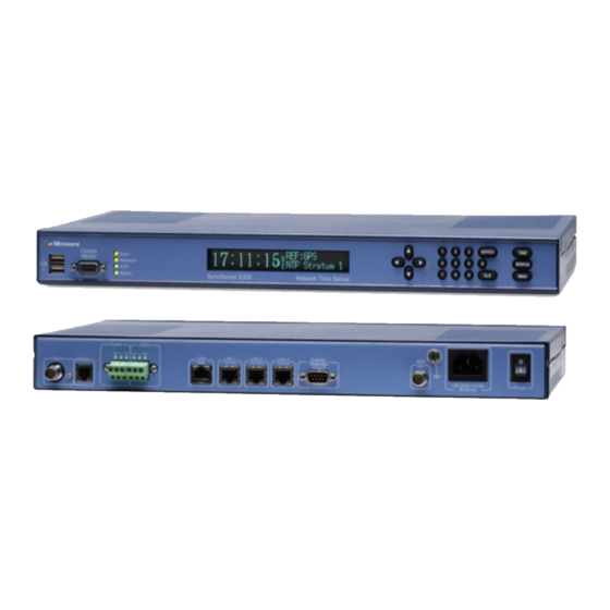
Page 112: Front Panel
Specifications WARNING: VDC Power WARNING: GPS Antenna WARNING: GPS Position and Altitude WARNING: Removing Power CAUTION: VAC Power CAUTION: DHCP Not Available CAUTION: Stopping the SyncServer CAUTION: Lithium Battery Front Panel The following elements are located on the front panel, from left to right. USBPorts Description:Two USB 2.0 ports (USB 1, 2). -
Page 113: Statusleds
Front Panel 4N/C 5GND 6N/C 7CTS 8RTS 9N/C StatusLEDs The four tricolor LEDs provide the following status information: Orange Green Dark Sync SyncServer is SyncServer is syn- SyncServer is synchronized to Power off. not synchronized chronized to a remote an Input Reference or the to a NTP server. -
Page 114: Rear Panel
Specifications Rear Panel The following elements are located on the rear panel, from left to right. Note: The SyncServer S350i does not include a GPS receiver, modem or LF radio. Radio(LFRadioModule) Description:The optional LF Radio Module (LFR) can be purchased with the SyncServer or sep- arately. -
Page 115: Networkports
Rear Panel Max. Operating Voltage:125 VAC, 60 VDC Max. Operating Current:1 A Max. Switching Capacity:37.5 VA, 30 W Min. Permissible Load:10 uA @ 10 mVDC Relay contacts: C is Common contact NO is Normally Open contact. NC is the Normally Closed contact. Relay states: C and NC (Normally Closed) C and NO (Normally Open) -
Page 116: Sysplexout
Specifications LANGbE192.168.0.103 Note: The SyncServer's network ports require Category 5 (or better) network cable. SysplexOut Summary:The Sysplex Timer port outputs serial time strings for IBM mainframe Sysplex sys- tems. The Sysplex Timer provides a common time reference across all the members of an IBM Sysplex. -
Page 117: 10Mhzin
Rear Panel <CR>Carriage Return (On-time marker) <LF>Line Feed 10MHzIn Description:10MHz In, a female BNC connector mounted on the rear chassis, accepts a 10MHz signal from an external frequency reference into the SyncServer's Hardware Clock. For the Syn- cServer to maintain lock to this signal, the stability of the 10MHz input must be better than the pull-range of the system oscillator. -
Page 118: 1Ppsout
Specifications Rubidium 1E-9 (1 ppb) Note: If the 1PPS In signal is too noisy, the Hardware Clock may not be able to lock to it. 1PPSOut Description:1PPS Out, a female BNC connector mounted on the rear chassis, provides a once per second pulse that is synchronous with the SyncServer's Hardware Clock. -
Page 119: Irigout(Timecodeout)
Rear Panel IRIG B 1344 DCLS IRIG B AM Legacy TrueTime IRIG B DCLS Legacy TrueTime IRIG E IRIG E AM 100Hz (with year) IRIG E AM 1KHz (with year) IRIG E DCLS (with year) IRIG E AM 100Hz (no year) IRIG E AM 1KHz (no year) IRIG E DCLS (no year) IRIG G... -
Page 120: Irig Control Function Bits
Specifications IRIG A IRIG B IRIG E A005 (DCLS, YR, CF) B005 (DCLS ,YR, CF) E112 (100 Hz) A006 (DCLS, YR) B006 (DCLS ,YR) E115 (100 Hz, YR, CF) A007 (DCLS, YR, SBS) B007 (DCLS ,YR, SBS) E116 (100 Hz, YR) A130 (10 kHz, CF, SBS) B120 (1 kHz, CF, SBS) E121 (1 kHz, CF) -
Page 121: Gpsreceiver
Rear Panel Index Bit countname ----- ----- 70 (bit = 0) 71 (bit = 0) 72 (bit = 0) 73 unlock (1 = unit is not locked to a reference) 74 (bit = 0) 75 tq1(1 = timing error estimate > 1us) 76 tq2 (1 = timing error estimate >... -
Page 122: Chassisgroundingscrew
Note: To connect a ground to the chassis, use a 3/8" 10-32 screw. Also see:WARNING: Grounding (on page 122) WARNING: Grounding Microsemi recommends that the user connect the chassis grounding screw to a reliable earth ground. AVERTISSEMENT : Microsemi recommande que le châssis soit relié à une terre fiable. -
Page 123: Warning: Vdc Power
Rear Panel WARNING: VDC Power For the 48 VDC model of the SyncServer: Use a disconnect device, such as a switch, with the appropriate voltage/current rating when connecting a VDC Power source. Only use the unit in an restricted area. The screw torque on the Power Terminal Block is 4.5 to 5.3 inch pounds. -
Page 124: Physical
5 CFM. AVERTISSEMENT : Installez le SyncServer pour permettre un flux d'air autour et a tra- vers l'unité. Microsemi recommande de laisser 1.4 in. (3.6 cm) au-dessus et au-dessous du SyncServer ou assez d'espace pour permettre 5 CFM. -
Page 125: Gps Antenna
GPS Antenna Synchronization Source Timing Accuracy to Reference Comments GPS, 1 Satellite, position <5 uS to UTC(USNO) Position from satellite fix known within 50m or entered by the user. GPS, 1 Satellite, position <100 uS to UTC(USNO) Position from satellite fix known within 1 km or entered by the user. -
Page 126: Timing Holdover
Specifications Impedance:50 ohms Voltage:5 - 18 VDC Power handling:1 watt Enclosure:All weather Operating temp:-55 °C to +85 °C (-67 °F to +185 °F) Note that the SyncServer model 350i does not have a GPS receiver. Timing Holdover Temperature Compensated Crystal Oscillator (TCXO) Feature:Standard Drift rate:18 milliseconds/day typical after having been locked to a stable reference for at least 30 minutes. -
Page 127: Ntp
99), ADMIN - Alarms (on page 85), and Status LEDs (on page 15). CE/WEEE/RoHS Conformance Declaration of Conformity In accordance with ISO/IEC GUIDE 22 and EN 45014: Microsemi Corporation Frequency and Time Division 3870 N. 1st Street San Jose, Ca 95134 USA... -
Page 128: Safety Standards
The SyncServer Model 1520R_SXXX is considered WEEE Category 3 (IT and Tele- communication Equipment) as defined by the WEEE Directive and therefore falls within the scope of the WEEE Directive. For more information about Microsemi's WEEE compliance and recycle program, please visit Microsemi's website at http://www.microsemi.com. RoHS... -
Page 129: Emc Standards
Note: In some cases, for FCC and CE EMC Radiated Emission Compliance, a ferrite EMI suppressor (Fair Rite P/N 0444164951 or equivalent) may need to be placed on the unit end of cables connected to the BNC Connectors. Please contact Microsemi Customer Assist- ance (on page 5) for additional information. -
Page 130: Reliability
MTBF:>50,000 hours (5.7 years) for all supported display intensity settings. Calculated per Tel- cordia (Bellcore) SR332, Issue 1. Maintainability This unit contains no user-serviceable parts. Please return to Microsemi for servicing. The SyncServer functions without user adjustments throughout its life span. Page 130................997-01520-02 Rev. F1... -
Page 131: Web Interface
SyncServer provides debug and troubleshooting variables of the current status of the unit at the request of an administrator. Warnings and Cautions WARNING:Grounding Microsemi recommends that the user connect the chassis grounding screw to a reliable earth ground. 997-01520-02 Rev. F1................ -
Page 132: Warning:vdcpower
Specifications AVERTISSEMENT : Microsemi recommande que le châssis soit relié à une terre fiable. Note: To connect a ground to the chassis, use a 3/8" 10-32 screw. WARNING:VDCPower For the 48 VDC model of the SyncServer: Use a disconnect device, such as a switch, with the appropriate voltage/current rating when connecting a VDC Power source. -
Page 133: Warning:gpspositionandaltitude
Warnings and Cautions Utilisez un "arrestor" d'éclair quand nécessaire. Les antennes qui n'ont pas étés évalués pour un courant de 12 VDC peuvent être endom- magées quand ils sont connectés au SyncServer. Jonction Sûre d'Antenne et de Câble : Relier ce système d'antenne ou de câble extérieur avec un contact adéquat de mise à... -
Page 134: Caution:dhcpnotavailable
Specifications CAUTION:DHCPNotAvailable If the user selects DHCP, the SyncServer tries to reach a DHCP server for approximately 90 seconds before stopping. Please do not disconnect the power during this time. ATTENTION : Si l'utilisateur choisit DHCP, le SyncServer essaye d'atteindre un serveur de DHCP pendant approximativement 90 secondes avant de s'arrêter. -
Page 135: Tasks
Tasks In this section Installation Guide Unpacking Rack Mounting Grounding the SyncServer Connecting VAC Power Electrical Installations in Norway and Sweden Connecting VDC Power Telecommunications (Modem) Interfaces Using GPS Configuring LAN1 Logging in to the Web Interface Using the 1st Setup Wizard Configuring the Network Ports Adding Server Associations Using the Other Input References... -
Page 136: Installation Guide
Introduction Unpacking Connecting and Finding a Signal Configuring the SyncServer Troubleshooting Antenna Locations Mounting Outdoors Additional Resources Microsemi Worldwide Sales Using Redundant Ethernet Ports About Redundant Ethernet Ports Configuring Redundant Ethernet Ports Verifying Redundancy Restoring Redundant Ethernet Ports Managing Users... -
Page 137: Rackmounting
Standard 6 ft. network cable Please also verify that the box also contains any options purchased with the SyncServer. If the box is missing any items, please contact Microsemi Customer Assistance (on page RackMounting The SyncServer is designed for mounting in a standard 19-inch (48.26 cm) rack. Follow the rack manufacturer's instructions for mounting the SyncServer. -
Page 138: Caution: Vac Power
Tasks Connect the VAC Input connector on the rear panel to a grounded three-prong outlet using the standard power cord supplied. CAUTION: VAC Power The VAC Power Supply specification reflects the overall Power Supply ratings. For UL and CE compliance the Power Supply must only be operated at 100 – 240 VAC, 50-60 The SyncServer should only be plugged into a grounded receptacle. -
Page 139: Warning: Vdc Power
Installation Guide Provide a circuit disconnect in series with the VDC Power input. The SyncServer DC option does not include a power switch The minimum recommended wire size is 14 AWG (1.5mm2) for DC power source hook up. Don’t forget to tighten the terminal screws on the input power block. The VDC Power supply in the SyncServer is DC isolated. -
Page 140: Usinggps
Tasks IMPORTANT SAFETY INSTRUCTIONS When using your telephone (modem) equipment, basic safety precautions should always be followed to reduce the risk of fire, electric shock and injury to persons, including the following: 1. Do not install modem during a storm. 2. -
Page 141: Selecting A Site For The Antenna
Installation Guide Utilisez un "arrestor" d'éclair quand nécessaire. Les antennes qui n'ont pas étés évalués pour un courant de 12 VDC peuvent être endom- magées quand ils sont connectés au SyncServer. Jonction Sûre d'Antenne et de Câble : Relier ce système d'antenne ou de câble extérieur avec un contact adéquat de mise à... -
Page 142: Installing The Gps Antenna
Tasks GPS Receivers can be susceptible to reflected GPS signals called multipath signals. Mul- tipath interference is caused by reflected signals that arrive at the antenna out of phase with the direct signal. This interference is most pronounced at low elevation angles from 10 to 20 degrees above the horizon. -
Page 143: Operating In "Window Mode
Installation Guide Note: Microsemi recommends posting a "Do not paint" notice to prevent the GPS antenna from being painted accidentally. Tips: The user can access the connector underneath the GPS antenna by removing the four recessed screws in the lower half of the GPS antenna with a Phillips-head screwdriver. It is a relatively easy task and does not violate the weatherproofing design of the antenna. - Page 144 After setting up the antenna: 1. On the TIMING - Holdover page, set the Time Error Limit (milliseconds) to the highest acceptable value for absolute timing error (to UTC). Microsemi recommends a value greater than or equal to 4 milliseconds.
-
Page 145: Verifying The Gps Installation
Review the GPS topics in this user guide Troubleshoot for issues with the GPS antenna and cable. Contact Microsemi Customer Assistance (on page 5). GPS Cable Configurations/Options GPS satellites signals operate in the L1 band (1575.42 MHz). GPS receivers require a min- imum signal level of -162.0 dBW. - Page 146 Tasks unobstructed view of the sky and thus be mounted on a roof, or in some cases in a window. GPS provides almost continuous operation day and night, and under poor weather con- ditions. Since the GPS signal is very weak, the antenna amplifies the signal to drive it through the cable to the receiver.
- Page 147 Installation Guide Typical mast mount of in-line amplifier GPS Down/Up converter: The GPS Down/Up converter makes cable runs of 250 to 1500 feet (75 m to 457 m) possible. GPS signal down conversion requires a special GPS antenna and corresponding signal up-converter. The antenna module converts the signal down to a lower frequency that has less attenuation, and transmits it the length of the cable to the up-con- verter.
-
Page 148: Configuringlan1
They require no addi- tional power or wiring except the ground lead. For more information about any of the options described above, please contact Microsemi Customer Assistance (on page 5). -
Page 149: Caution: Dhcp Not Available
Also see WIZARDS - 1st Setup (on page 99). Configuringthe Network Ports Configure the remaining network ports using NETWORK - Ethernet. Microsemi Recommends: Using static IP addresses. (See explanation below.) Using Allowed Access to protect the network ports from unauthorized IP addresses or address ranges. -
Page 150: Addingserverassociations
Tasks AddingServerAssociations NTP server and peer associations provide an important backup source of time if the Syn- cServer's Input References are unavailable. Having two or more server or peer associations is important for reliability and redundancy. (Optional) The user can add associations for NTP servers that reside on the company net- work: For NTP servers that the user cannot configure, add server associations, as described below. -
Page 151: Troubleshooting
A numbered step is a procedure. The user should complete the procedure to solve the problem. For additional help, contact Microsemi Customer Assistance (on page 5). Passwords You've tried logging in and the password doesn't work. Passwords are case sensitive. Check that that Caps Lock isn't on. -
Page 152: Upgrading System Software
Having the backup makes it possible to restore the previous settings if that happens. The user downloads the software upgrade file from the Microsemi web site to their work- station and then follows the steps given below for upgrading the software on the Syn- cServer. - Page 153 Or, manually check for an upgrade by comparing the Release Version on the STATUS - General page with the Version at http://update.symmetricom.com/upgradeS300.txt. Downloading the Upgrade 1. Unless instructed to use another URL, download the software from Microsemi's online portal at http://www.microsemi.com. 2. Save the software to your workstation or to the USB flash drive.
-
Page 154: Webinterface
Tasks WebInterface You can't reach the web interface. Check that LAN1 is physically connected to the network. Ping the IP Address of LAN1. Check that the LAN1 IP Address, Mask, and Gateway are valid using the STATUS but- ton to display LAN1 STATUS. LAN1 may be disabled. -
Page 155: Addingpeer Associations
Using NTP the name of your country at the end of the search string. When available, select NTP servers that are stratum 1 over those that are stratum 2. To add a server association: 1. Go to NTP - Config in the web interface. 2. -
Page 156: Addingbroadcastassociations
NTP broadcast clients settle into a routine of listening for, and synchronizing with, the NTP broadcast messages. Microsemi recommends consulting with your IT department or network administrator before broadcasting NTP. The user should configure the scope of the broadcast address to cover the intended subnet. -
Page 157: Addingmulticastassociations
Using NTP Creating a broadcastclient association To configure an NTP client as a broadcast client, consult the manufacturer's documentation. To configure a generic NTP broadcast client with MD5 authentication, the user would upload the ntp.keys file to the /etc directory and add the following lines to the ntp.conf file (example values italicized): broadcastclient enable auth... -
Page 158: Configuringntpclients
Tasks 5. For MD5 Key, select the appropriate method, Key or Auto. (If selecting Key, also select a key number, 1 through 16.) 6. Click the SAVE button. 7. Click the RESTART button. When the NTP daemon finishes restarting, it broadcasts NTP messages every 64 seconds. -
Page 159: Usingthemodemfordial-Uptime Service
Using NTP UsingtheModemforDial-upTime Service The SyncServer S350i does not include a modem. The modem provides dial-up time service over ordinary telephone lines (POTS). It functions as a stratum 1 NTP server association, not as a Input Reference to the Hardware Clock. The SyncServer typically uses the modem as a backup NTP reference if no other NTP ref- erences are available (no Input References, or reachable NTP servers and peers). -
Page 160: Workingwithgeneric Ntpdevices
Tasks WorkingwithGeneric NTPDevices This topic provides a starting point for users to work with NTP on a UNIX or Linux operating system. For more information, consult the manufacturer's documentation or search online for information about a particular device or operating system. Log in as the root user. -
Page 161: Using Md5 Keys On A Syncserver
Using NTP Using MD5 Keys on a SyncServer A high level description of how to set up MD5 authentication between two NTP devices: 1. Generate the MD5 keys on one device. 2. Securely transfer the keys to the other device. 3. -
Page 162: Using Md5 Keys On A Generic Ntp Device
Tasks The SyncServer automatically trusts all of the NTP keys. Using MD5 Keys on a Generic NTP device This topic is a guide to configuring MD5 authentication for NTP on a UNIX or Linux operating system. Specifics, such as the location of files, vary by implementation. Note: ... -
Page 163: Using Autokey
Using NTP Save the changes and close the file. In vi, press the Esc key and enter: Restart ntpd. The most reliable way to do this is to reboot the system by entering: shutdown -r now When the system and ntpd restart, the new configuration should be in effect. Note: Mismatched keys or partially configured authentication may prevent synchronization between two NTP nodes. -
Page 164: Enabling Secure Login
Tasks 1. Log in to the other SyncServer securely. 2. On the NTP - Autokey Client page, select the Identity Scheme that was used to generate the keys. 3. Enter the Server Password or Client Password used at the time the user generated the cer- tificates and keys: If the Identity Scheme is PC or GQ, enter the Server Password. -
Page 165: Halting The Syncserver
167). See also: Properties of User Names and Passwords (on page 23) Halting the SyncServer Microsemi recommends shutting the operating system down before removing the power. Using the keypad/display interface: 1. Press the MENU button. 2. Select 3) Sys Control. -
Page 166: Creatingabackupfile
Any directory that is accessible to a browser. Notes: - Not all USB flash drives are compatible with the SyncServer's USB ports. Microsemi recom- mends using SanDisk cruzer micro USB devices. - The backup file includes the configuration of the NETWORK - Ethernet page. If restoring a single configuration to multiple units, if the network ports have static IP addresses, avoid IP address conflicts by changing these addresses. -
Page 167: Restoringfrom Abackupfile
Backing Up/Restoring Configurations 2. Then use the SAVE AS or COPY button to download the backup file to a your workstation or a USB device. Restoringfrom aBackupFile From the front panel keypad 1. Plug the USB flash drive into the 'target' SyncServer. 2. - Page 168 Tasks When the password is lost and the Recover Password feature is disabled (Use the Hard- ware Jumper method). To erase the previous configuration prior to reconfiguring the SyncServer. To erase site-specific information such as the IP addresses and the GPS position, prior to sending the SyncServer off-site.
-
Page 169: Warning: Removing Power
Removing the Top Cover WARNING: Removing Power Prior to removing the top cover, disconnect all power connections. AVERTISSEMENT : Avant d'enlever le couvercle, débranchez le courant électrique.. Removing the Top Cover After halting the SyncServer as described in Halting the SyncServer (on page 15): 1. -
Page 170: Using Lf Radio
Please note that the LFR option provides the least accurate timing reference to the Syn- cServer’s hardware clock (in the milliseconds range). This option is intended for use as a backup to more accurate Input References. Please feel free to contact Microsemi Worldwide Saleshttp://www.microsemi.com/sales- contacts/0 online to borrow a stand-alone kit for evaluating LF Radio reception in a variety of locations. -
Page 171: Unpacking
LFR module (Disk-shaped) Mounting bracket (part #4186-8P) and a bag of 4 mounting screws 9 volt battery holder with TNC connector (part #110-6210) Please contact Microsemi Customer Assistance (on page 5) if any items are missing or damaged. ConnectingandFindingaSignal Choosing a Site LF signals can penetrate structures and are often available indoors, particularly at night when LF signal strength and range are highest. - Page 172 Tasks 2. Connect the battery holder/TNC cable to the LFR. Use power from the SyncServer to test signal strength nearby while graphing signal strength over several days: 1. Connect the supplied 50 foot (15.24 m) RG-59 cable to the TNC connector on the LFR. 2.
-
Page 173: Configuringthe Syncserver
NIST Radio Station WWVB http://tf.nist.gov/stations/wwvb.htm PTB Website for DCF-77 http://www.ptb.de/en/org/4/44/442/dcf77_1_e.htm Japan Standard Time Project - JJY http://jjy.nict.go.jp/jjy/index-e.html MicrosemiWorldwide Sales Note: Please feel free to contact Microsemi Worldwide Saleshttp://www.- microsemi.com/sales-contacts/0 online about borrowing a kit for testing Low Frequency 997-01520-02 Rev. F1................Page 173... -
Page 174: Using Redundant Ethernet Ports
Tasks Radio (LFR) reception prior to purchasing the LFR option. Using Redundant Ethernet Ports AboutRedundantEthernetPorts The SyncServer's LAN2 and LAN3 network ports can be bonded together as a single, phys- ically redundant, Ethernet connection with a single IP address. Bonding can be used to reduce the Ethernet connection's susceptibility to a single-point failure. -
Page 175: Restoringredundantethernetports
Managing Users 4. Reconnect LAN3 to the network. 5. Disconnect LAN2 from the network. LAN2 becomes backup and LAN3 becomes active. 6. PING the IP Address of the bonded ports. The PING statistics should show 0% lost. This confirms that LAN3 is active. 7. -
Page 176: Creatinganewuser
Tasks 2. Select a Recovery Question and enter the Answer. 3. Enter an Email Address and the SMTP Gateway's DNS name (if LAN1 can reach a DNS server on the network) or IP address (if DNS is not available). 4. (Optional) Select the Send Test Email checkbox. 5. -
Page 177: Setting The Time Manually
0.875ms/hr * 3 hrs or 2.625 milliseconds. If your SyncServer has a Rubidium oscillator, the time error would be 0.001ms/hr * 3 hrs or 0.003 milliseconds. Note: To minimize the accumulated time error during outages, Microsemi recommends pur- chasing SyncServer with the Rubidium oscillator option. A SyncServer equipped with a Rubidium oscillator can maintain time to better than one millisecond accuracy to UTC with GPS satellite outages of one month. -
Page 178: Distributing Gps Time
Tasks associations are available, the SyncServer's NTP daemon may synchronize with one of them instead of the Hardware Clock. Using the Command Line 1. Log in to the command line interface. 2. Enter the SETTIMEOFYEAR command followed by the time in one of the following formats: mm/dd/yyyy hh:mm:ss.x yyyy ddd hh:mm:ss.x MON dd yyyy hh:mm:ss.x... - Page 179 Distributing GPS Time 5. On the SERVICES - Startup page, under System Control, select Reboot and click the APPLY button. 6. (Optional) After the SyncServer restarts, compare the seconds on the front panel time dis- play with some other accurate time display. The GPS time should be ahead of the UTC or standard time display by the value of the GPS-UTC Offset.
-
Page 180: Distributing Non-Utc Time
CAUTION: Switching between GPS and UTC references while Ignore UTC Corrections from GPS Reference is enabled may have undesirable effects and should be avoided. Microsemi recommends disabling and removing all UTC-synchronized Hardware Clock Input References and NTP associations to prevent this from happening. -
Page 181: Configuring Snmp
Configuring SNMP See the Setting the Time Manually (on page 177) topic. While reading the text, substitute "UTC time" with "non-UTC time". Synchronizing to non-UTC NTP 1. On the TIMING - HW Clock page, disable all of the Input References and click the APPLY but- ton. -
Page 182: Snmpmib
Tasks SNMPMIB The following text comes from the SyncServer's Custom MIB, symm-smi.txt, located on the Product Information CD: SYMM-SMI DEFINITIONS ::= BEGIN IMPORTS OBJECT-TYPE, MODULE-IDENTITY, OBJECT-IDENTITY FROM RFC-1212 DisplayString FROM RFC1213-MIB TRAP-TYPE FROM RFC-1215 enterprises, Integer32, Unsigned32 FROM RFC1155-SMI; symmetricom MODULE-IDENTITY LAST-UPDATED "1013061200Z"... - Page 183 Configuring SNMP STATUScurrent DESCRIPTION "This is the root object identifier for SNMP based objects." ::= { symmNetworkManagement 2 } symmTimePictra OBJECT-IDENTITY STATUScurrent DESCRIPTION "This is reserved for objects related to Symmetricom's TimePictra products." ::= { symmSnmpManagement 1 } symmBroadband OBJECT-IDENTITY STATUScurrent DESCRIPTION "The subtree that contains objects related to Symmetricom's GoWide products."...
- Page 184 Tasks "NTP Leap Indicator. This is a two-bit code warning of an impending leap second to be inserted into the NTP timescale. The bits are set before 23:59 on the day of insertion and reset after 00:00 on the following day. This causes the number of seconds (rollover interval) in the day of insertion to be increased or decreased by one. ...
- Page 185 Configuring SNMP The value must be rounded to the next larger power of two; for instance, a 50-Hz (20ms) or 60-Hz (16.17ms) power-frequency clock would be assigned the value -5 (31.25ms), while a 1000-Hz (1ms) crystal-controlled clock would be assigned the value -9 (1.95ms)." ::= {ntpSystem 3} ntpSysRootDelay OBJECT-TYPE SYNTAXOCTET STRING...
- Page 186 Tasks GPS GPS UHF satellite positioning ============================================== The following ref ids are used by the SyncServer: ============================================== GPS GPS satellite) IRIG IRIG B timecode PPS Ext. 1PPS input E10M Ext. 10MHz input FREE Internal Clock FLY Internal Clock after the Hardware Clock reference is lost =============================================="...
- Page 187 Configuring SNMP MAX-ACCESSread-only STATUScurrent DESCRIPTION "System clock offset from the selected source." ::= {ntpSystem 10} ntpSysFreq OBJECT-TYPE SYNTAXDisplayString (SIZE(1..40)) MAX-ACCESSread-only STATUScurrent DESCRIPTION "System clock frequency correction from ntpd." ::= {ntpSystem 11} ntpSysError OBJECT-TYPE SYNTAXDisplayString (SIZE(1..40)) MAX-ACCESSread-only STATUScurrent DESCRIPTION "Current system error from ntpd." ::= {ntpSystem 12} ntpSysClock OBJECT-TYPE SYNTAXDisplayString (SIZE(1..40))
- Page 188 Tasks DESCRIPTION "Force authentication." ::= {ntpSystem 16} ntpSysPktsReceived OBJECT-TYPE SYNTAX INTEGER (0..32768) ACCESS read-only STATUS mandatory DESCRIPTION "This variable is a rollover counter which reflects the number of ntp packets received by the SyncServer. It is valid for all versions of the SyncServer." ::= {ntpSystem 17} ntpSysMode OBJECT-TYPE SYNTAX INTEGER {...
- Page 189 Configuring SNMP STATUScurrent DESCRIPTION "Indicates what status the Hardware Clock considers itself to be as a timing source defined as follows: ============================================ Good HW Clock has a valid time reference. Bad HW Clock has no valid time reference. ============================================" ::= {tyming 1} tymingSource OBJECT-TYPE SYNTAX DisplayString (SIZE(1..40)) MAX-ACCESS read-only...
- Page 190 Tasks SYNTAX DisplayString (SIZE(1..40)) MAX-ACCESS read-only STATUS current DESCRIPTION "The version of the software on the SyncServer's Hardware Clock." ::= {tyming 4} tymingFlyPeriod OBJECT-TYPE SYNTAX INTEGER MAX-ACCESS read-only STATUS current DESCRIPTION "This variable is not currently used and returns zero." ::= {tyming 5} gpsPosition OBJECT-TYPE SYNTAXDisplayString (SIZE(1..80))
- Page 191 Configuring SNMP gpsHealth OBJECT-TYPE SYNTAXDisplayString (SIZE(1..80)) MAX-ACCESSread-only STATUScurrent DESCRIPTION "This is the GPS’ receiver health status defined as follows: ====================================================== 0 = Receiver Down The Hardware Clock can't communicate with the receiver. 1 = Unknown Mode An undefined mode of the GPS receiver.
- Page 192 Tasks "Displays the GPS satellite tracking information in the format of: N,X1,Y1,Z1,...,XN,YN,ZN defined as follows: ====================================================== N Number of satellites. If one or more satellites are available, Xi,Yi,Zi follows N. Xi Satellite vehicle number. Yi Satellite signal strength in dBW where less than -200 dBW means no signal.
- Page 193 Configuring SNMP Receiver Mode: Dynamic. The GPS receiver surveys continuously to determine its position and doesn't switch to another mode. This mode must be initiated by a user, and is appropriate for mobile applications such as ships, land vehicles, and aircraft. The degree of accuracy this mode offers is fine for NTP time over networks, but is less than optimal for the IRIG-B, 1PPS, 10MHz outputs available on some SyncServer models. ...
- Page 194 Tasks the upgrade server described as follows: ====================================================== 0 No upgrade is available. 1 An upgrade is available. ======================================================" ::= {etc 4} etcUpgradeServer OBJECT-TYPE SYNTAXDisplayString (SIZE(1..1024)) MAX-ACCESSread-only STATUScurrent DESCRIPTION "Address of the server where new upgrades can be downloaded." ::= {etc 5} etcAlarmString OBJECT-TYPE SYNTAXDisplayString (SIZE(0..1024)) MAX-ACCESSread-only...
-
Page 195: Glossary
Command Line Glossary Command Line Hardware Clock Input References Leap Indicator NTP Associations NTP Daemon NTP Packet PING PTP (Precision Time Protocol Stratum Synchronizing NTP association Operational Configuration Command Line The command line is a text-based user interface available on most operating systems. For example, on Microsoft Windows, open the Start menu, select Run, and enter cmd. -
Page 196: Hardware Clock
Glossary other corrections which are periodically added to UTC. GPS time was set to match Coordin- ated Universal Time (UTC) in 1980, but has since diverged. [...] The GPS navigation message includes the difference between GPS time and UTC, which as of 2006 is 14 seconds. -
Page 197: Leap Indicator
Leap Indicator The GPS, Timecode, and LF Radio reference inputs provide time and phase, while the 1PPS, and 10MHz inputs provide phase only. The modem, which provides dial-up time service, is not an Input Reference; it is a server association on the NTP daemon. Leap Indicator The Leap Indicator (LI) is a two-bit binary number in the NTP packet header that provides the following information:... -
Page 198: Ntp Daemon
Glossary NTP Daemon The Network Time Protocol (NTP) Daemon (a.k.a. "ntpd") listens for and responds to requests from NTP clients. It also sends NTP requests to each of the NTP Associations and qualifies each one. It synchronizes with the best NTP association and makes that time avail- able to the See the NTP - Config (on page 43) topics for more information. - Page 199 NTP Packet Advance warning that a leap second adjustment will be made to the UTC timescale at the end of the current day. Leap seconds are events mandated by the world time authority (BIPM) in order to synchronize the UTC time scale with the earth's rotation. Whether the NTP daemon is synchronized to a timing reference.
- Page 200 Glossary Stratum Definition Primary server 2-15 Secondary server 16-255 Unsynchronized, unreachable. For example, the SyncServer is: stratum 1 when the Hardware Clock (stratum 0) is synchronized to an input reference, in holdover mode, or in freerun mode. stratum 2 through 15 when it is synchronized to a remote NTP server. stratum 16 when it is unsynchronized, indicating that it is searching for a valid source of timing information.
-
Page 201: Ping
PING DCF7LF Radio DCF77, Mainflingen, DE, 77.5 kHz MSFLF Radio MSF, Rugby, UK, 60 kHz JJYLF Radio JJY, Fukushima, JP, 40 kHz, JJYLF Radio JJY, Saga, JP, 60 kHz WWVHF Radio WWV, Ft. Collins, CO WWVHHF Radio WWVH, Kaui, HI NISTNational Institute of Standards and Technology telephone modem PTBPhysikalisch-Technische Bundesanstalt telephone modem For strata 2-15 secondary servers, this is the reference identifier of the system peer. -
Page 202: Ptp
Glossary device to be reached. If the device is unreachable, the response is typically "request timed out." If the device was reachable, the response is "reply from..." followed by various ping stat- istics. The ping utility is available on the SyncServer's NETWORK - Ping page, and from the command line on most operating systems. -
Page 203: Operational Configuration
Operational Configuration announced at irregular intervals to compensate for the earth's slowing rotation and other dis- crepancies. Leap seconds allow UTC to closely track Universal Time (UT), a time standard based not on the uniform passage of seconds, but on Earth's angular rotation." Operational Configuration A common configuration of the SyncServer needed for operation under a range of typical conditions. -
Page 205: Index
Index 10MHz In 117 10MHz Out 117 1PPS In 117 1PPS Out 118 About Redundant Ethernet Ports 174 Accuracy & Stability - Timing Performance 124 Adding Broadcast Associations 156-157 Adding Multicast Associations 157 Adding Peer Associations 150, 154-155 Adding Server Associations 150-151, 154 Additional Resources 173 ADMIN - Alarms 85, 92, 103, 127, 152 ADMIN - Logs Config 90... - Page 206 Index Configuring SNMP 181 Configuring the Network Ports 149, 151 Configuring the SyncServer 13, 173 Connecting and Finding a Signal 171 Connecting VAC Power 137 Connecting VDC Power 138 Console RS-232 Port 112 Contact Information 4 Copyright 3 Creating a Backup File 153, 166-168 Creating a New User 176 Deleting a Current User 176 Distributing GPS Time 62, 178, 180...
- Page 207 LOGS 97 Maintainability 130 Managing Users 84, 175 MENU Button 104, 148 Microsemi Customer Assistance 5, 76, 107, 129, 131, 137, 145, 148, 151, 171 Microsemi Worldwide Sales 173 Modem 114 Mounting Outdoors 173 NETWORK - Ethernet 32, 99, 103, 149...
- Page 208 Index NTP Clients 151 NTP Daemon 198 NTP Daemon Status 28, 39, 44, 51 NTP Packet 28, 39, 198 Operating in 66, 70, 142-143 Operational Configuration 203 Passwords 151 Physical 124 PING 174, 201 Power and Alarm Relays 92, 114 Power Switch 123 Product Overview 17, 26 Properties of User Names and Passwords 23, 81, 84, 151, 165, 175-176...
- Page 209 Selecting a Site for the Antenna 141 SERVICES - Email 97 SERVICES - HTTP 96 SERVICES - SSH 97 SERVICES - Startup 95 Setting the Time Manually 62, 71, 177, 181 Shock and Vibration 124 SNMP MIB 182 Software 131 Specifications 13, 111 STATUS - Alarms 32 STATUS - General 24...
- Page 210 Index Using MD5 Keys on a generic NTP device 161-162 Using MD5 Keys on a SyncServer 47, 157-158, 161 Using NTP 154, 181 Using NTP Authentication 45, 48, 156-158, 160 Using Redundant Ethernet Ports 174 Using the 1st Setup Wizard 149 Using the Modem for Dial-up Time Service 114, 159 Using the Other Input References 150-151 UTC 202...
Need help?
Do you have a question about the SyncServer S300 and is the answer not in the manual?
Questions and answers