Advertisement
Available languages
Available languages
Quick Links
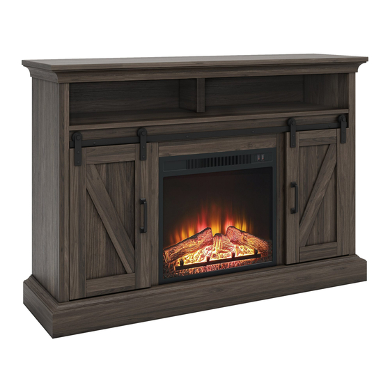
48" Barn Door Fireplace
If you have any questions regarding assembly or if parts are missing, DO NOT return this item to the
store where it was purchased. Please call our customer service number and have your instructions
and parts list ready to provide the model name, part name or factory number:
Pacific Standard Time: 8:30 a.m. - 4:30 p.m., Monday - Friday
Or visit our web site 24 hours a day, 7 days a week for product assistance at
THIS INSTRUCTION BOOKLET CONTAINS IMPORTANT SAFETY INFORMATION.
Stock # WMFP48EC-22
ADULT ASSEMBLY REQUIRED
www.whalenstyle.com
Or e-mail your request to parts@whalenfurniture.com
PLEASE READ AND KEEP FOR FUTURE REFERENCE.
Date 2018-07-12 Rev. 0001-A Factory: HESLTD
866-942-5362
LOT NUMBER:
DATE PURCHASED:
/
/
Advertisement

Related Manuals for Whalen 48" Barn Door Fireplace


Summary of Contents for Whalen 48" Barn Door Fireplace
- Page 1 LOT NUMBER: DATE PURCHASED: 48" Barn Door Fireplace Stock # WMFP48EC-22 ADULT ASSEMBLY REQUIRED If you have any questions regarding assembly or if parts are missing, DO NOT return this item to the store where it was purchased. Please call our customer service number and have your instructions and parts list ready to provide the model name, part name or factory number: 866-942-5362 Pacific Standard Time: 8:30 a.m.
-
Page 2: Special Note
M A X I M U M R E C O M M E N D E D W E I G H T L O A D S MANUFACTURER: Whalen Furniture Manufacturing CATALOG: 48" Barn Door Fireplace MODEL # WMFP48EC-22 MADE IN CHINA FITS UP TO MOST 60”... - Page 3 IMPORTANT Before you begin: Open, identify and count all parts prior to assembly. Lay out parts on a flat and non- abrasive surface. You will need the parts identified on page 4 and 5 of this instruction manual. NOTE: IT IS VERY IMPORTANT TO USE GLUE WITH DOWELS. EXCESS GLUE CAN BE WIPED OFF WITH DAMP CLOTH.
-
Page 4: Parts And Hardware List
Parts and Hardware List Please read completely through the instructions and verify that all listed parts and hardware are present before beginning assembly. A- Top Panel (Qty. 1) B- Fixed Shelf (Qty. 1) C- Bottom Panel (Qty. 1) D- Left Side Panel (Qty. 1) E- Right Side Panel (Qty. - Page 5 Parts and Hardware List Please read completely through the instructions and verify that all listed parts and hardware are present before beginning assembly. (1) Cam Lock (2) Cam Bolt (3) M8 x 30 mm Wood Dowel (Qty. 50+2 extra) (Qty. 50+2 extra) (Qty.
-
Page 6: Assembly Instructions
Assembly Instructions Cam Bolt (6 used in this step) ② 1. Unpack the unit and confirm that you have all the hardware and required parts. Assemble the unit on a carpeted floor or the empty carton to avoid any scratch. 2. - Page 7 Assembly Instructions Cam Lock (2 used in this step) ① 3. Align the drilled holes on the Upper Partition Panel (F) with the installed Cam Bolts (2) on the Upper Partition Panel Molding (G), and then press them together. Secure the Upper Partition Panel Molding (G) in place by engaging two Cam Locks (1) (Refer to page 3 on Cam Lock system operation supplement).
- Page 8 Assembly Instructions Cam Lock (4 used in this step) ① M8 x 30 mm Wood Dowel (4 used in this step) ③ 4. Insert two 30 mm Wood Dowels (3) into the inner holes of the Left Lower Partition Panel (H). Tap them in with a rubber mallet, if necessary.
- Page 9 Assembly Instructions Cam Bolt (28 used in this step) ② 7. Securely screw the Cam Bolts (2) into the designated small holes on the Panels (A, B and C) and the Side Panel Front Moldings (V) with a Phillips screwdriver.
- Page 10 Assembly Instructions Cam Bolt (14 used in this step) ② 8. Securely screw the Cam Bolts (2) into the designated small holes on the Left and Right Side Panels (D and E) and the Fixed Shelf Molding with Hanging Bar (J) with a Phillips screwdriver.
- Page 11 Assembly Instructions Cam Lock M8 x 30 mm Wood Dowel (6 used in this step) (4 used in this step) ① ③ 9. Attach one Side Panel Front Molding (V) to the Left Side Panel (D) with two 30 mm Wood Dowels (3) and three Cam Locks (1).
- Page 12 Assembly Instructions M8 x 30 mm Wood Dowel Cam Lock (8 used in this step) (6 used in this step) ③ ① 11. Attach the Bottom Back Stretcher (P) to the Bottom Panel (C) with three 30 mm Wood Dowels (3) and four Cam Locks (1).
- Page 13 Assembly Instructions Cam Lock M8 x 30 mm Wood Dowel (2 used in this step) (2 used in this step) ③ ① 13. Attach the Middle Crossbar (M) to the Fixed Shelf Molding with Hanging Bar (J) with two 30 mm Wood Dowels (3) and two Cam Locks (1).
- Page 14 Assembly Instructions M4 x 50 mm Screw M8 x 30 mm Wood Dowel (4 used in this step) (4 used in this step) ③ ④ 14. Glue two 30 mm Wood Dowels (3) into the bottom inner holes of the Left Lower Partition Panel (H) and attach it to the Bottom Panel (C) with two 50 mm Screws (4).
- Page 15 Assembly Instructions Cam Lock (4 used in this step) ① M8 x 30 mm Wood Dowel (4 used in this step) ③ 16. Attach the assembled Fixed Shelf (B) to the Lower Partition Panels (H and I) with four Cam Locks (1) and four 30 mm Wood Dowels (3).
- Page 16 Assembly Instructions Cam Lock M8 x 30 mm Wood Dowel (12 used in this step) (12 used in this step) ① ③ 17. Attach the Left Side Panel (D) to the left side of assembled unit with six Cam Locks (1) and six 30 mm Wood Dowels (3).
- Page 17 Assembly Instructions Cam Lock M8 x 30 mm Wood Dowel (4 used in this step) (3 used in this step) ① ③ 19. Attach the Bottom Front Stretcher (O) to the Bottom Panel (C) with four Cam Locks (1) and three 30 mm Wood Dowels (3).
- Page 18 Assembly Instructions M4 x 50 mm Screw (4 used in this step) ④ 20. Fasten the Bottom Front Stretcher (O) to the Side Panels (D and E) with four 50 mm Screws (4).
- Page 19 Assembly Instructions M4 x 25 mm Screw (8 used in this step) ⑤ M8 x 20 mm Wood Dowel (2 used in this step) 21. Attach the Bottom Front Molding (N) to the Bottom Front Stretcher (O) with two 20 mm Wood Dowels (17) and eight 25 mm Screws (5).
- Page 20 Assembly Instructions Floor Leveler (2 used in this step) ⑥ 22. Install the Floor Levelers (6) to the bottom of the Bottom Front Molding (N). Adjust the levelers in the correct height.
- Page 21 Assembly Instructions Cam Bolt (2 used in this step) ② 23. Ask for assistance to stand the previous assembly upright. 24. Securely screw the Cam Bolts (2) into the designated small holes on the Fixed Shelf (B) with a Phillips screwdriver.
- Page 22 Assembly Instructions Cam Lock M8 x 30 mm Wood Dowel (1 used in this step) (2 used in this step) ① ③ 25. Attach the assembled Upper Partition Panel with Molding (F and G) to the Fixed Shelf (B) with two Cam Locks (1) and one 30 mm Wood Dowel (3).
- Page 23 Assembly Instructions Cam Lock (6 used in this step) ① M8 x 30 mm Wood Dowel (5 used in this step) ③ 26. Glue five 30 mm Wood Dowels (3) into the inner holes of the panels (D, E and F). Ask for assistance to align and position the Top Panel (A) onto the panels (D, E and F) and secure them in place with six Cam Locks (1).
- Page 24 Assembly Instructions M3.5 x 15 mm Screw (4 used in this step) ⑦ Straight Metal Bracket (2 used in this step) ⑧ 27. Now, go back and securely tighten all the Cam Locks and the Screws. Make sure that all the parts are tight and there are no gaps between the parts.
- Page 25 Assembly Instructions M3.5 x 15 mm Washer Head Screw (28 used in this step) ⑨ 30. Pick up the Upper Back Panel (T) and align the pre-drilled holes against the upper long edge with the pilot holes on the back stretcher of Top Panel (A). Attach the Upper Back Panel (T) in place using the provided 15 mm Washer Head Screws (9).
- Page 26 Assembly Instructions M3.5 x 15 mm Screw L-Shaped Metal Bracket (4 used in this step) (2 used in this step) ⑦ 32. Ask for assistance to stand the assembled unit upright. 33. With pilot holes as a guide, install two L-Shaped Metal Brackets (12) to the Bottom Panel (C) with four 15 mm Screws (7).
- Page 27 Assembly Instructions Handle 22 mm Handle Bolt (2 used in this step) (4 used in this step) ⑩ 34. Attach one Handle (10) to the front side of the Left Door (R) with two 22 mm Handle Bolts (11). 35. Repeat the same procedure with the Right Door (S).
- Page 28 Assembly Instructions Barn Door Roller (4 used in this step) 36. Hook four Barn Door Rollers (13) onto the pre-attached hanging bar on the Fixed Shelf Molding with Hanging Bar (J).
- Page 29 Assembly Instructions M4.5 x 19 mm Screw (8 used in this step) 37. Take the Left Door (R) and fit the bottom groove onto the installed L-Shaped Metal Brackets (12) on Bottom Panel (C) properly. Proceed to attach the two Barn Door Rollers (13) to the top rail of the Left Door (R) with four 19 mm Screws (14), using the pilot holes as a guide.
- Page 30 Assembly Instructions Rubber Bumper Shelf Pin Cam Lock Cover (6 used in this step) (8 used in this step) (20 used in this step) 39. Insert four Shelf Pins (15) into the desired holes inside each side compartment. Tilt and rest the Adjustable Shelves (Q) onto the Shelf Pins (15).
- Page 31 Assembly Instructions 42. Unpack the fireplace insert from the inner box and follow the instructions to install the Top Trim and Side Trims to the fireplace insert. 43. Lift the fireplace insert carefully into the back of the assembled mantel and center it in the opening. DO NOT drag the insert across the Bottom Panel (C) as it may scratch the unit.
- Page 32 Assembly Instructions NOTE: To prevent your TV from tipping, you must install the Strip Stopper if you place your flat panel television directly on the console. Otherwise, skip to step 45. 45. Remove the paper backing from the Stopper Rail (W), then properly align the Stop Rail with the top edge of the stopper template on Top Panel (A).
- Page 33 Assembly Instructions Tools required (not provided): Phillips screwdriver, stud finder, power drill and 1/8" drill bit. 47. Ask for assistance to position the assembled fireplace at the desired location against a wall. If necessary, adjust the installed Floor Levelers at the Bottom Front Molding (N) to level the unit. 48.
-
Page 34: Care And Maintenance
Should this product be defective in workmanship or materials or fail under normal use, we will repair or replace it for up to one (1) year from date of purchase. Every Whalen Furniture product is designed to meet your highest expectations. We guarantee that you will immediately see the value of our fine furniture. - Page 35 LOTE NÚMERO: FECHA DE COMPRA: Chimenea puerta de granero de 48" Serie # WMFP48EC-22 ENSAMBLE REQUERIDO POR ADULTO Si tienen alguna pregunta acerca del ensamble o si alguna parte está faltante, no retorne esté producto a la tienda donde lo compró. Por favor llame a nuestro departamento de ayuda al cliente teniendo su instructivo y lista de partes para proveer el modelo, nombre de parte o el número de fábrica: 866-942-5362 Hora Estándar del Pacífico: 8:30 a.m.
- Page 36 PESOS MÁXIMOS RECOMENDADOS FABRICANTE: Whalen Furniture Manufacturing CATALOGO: Chimenea puerta de granero de 48" MODELO # WMFP48EC-22 HECHO EN CHINA PARA MAYORÍA DE LAS TELEVISIONES DE PANTALLA PLANA DE 60” CARGA MÁXIMA 135 lb. (61.3 kg) POSICIONE LA TELEVISIÓN ATRÁS DEL TOPE CARGA MÁXIMA 50 lb.
- Page 37 IMPORTANTE Antes de comenzar: Abra, identifique y cuente todas las partes antes del ensamble. Coloque las piezas sobre una superficie plana y no abrasiva. Tendrá que las partes identificadas en la página 4 y 5 de este manual de instrucciones. NOTA: ES MUY IMPORTANTE PARA EL USO DE PEGAMENTO CON LOS PERNSO DE MADERA.
- Page 38 Lista de partes y material de ferretería Por favor lea completamente las instrucciones y verifique que estén todas las partes antes de iniciar el ensamblado. A- Panel superior (Cant. 1) B- Repisa fija (Cant. 1) C- Panel inferior (Cant. 1) D- Panel izquierdo (Cant.
- Page 39 Lista de partes y material de ferretería Por favor lea completamente las instrucciones y verifique que estén todas las partes antes de iniciar el ensamblado. (1) Tuerca de fijación (2) Perno de fijación (3) Clavija de madera de M8 x 30 mm (Cant.
- Page 40 Instrucciones de ensamble Perno de fijación (6 usados en este paso) ② 1. Desempacar la unidad y confirmar que se tiene todo el material de ferretería y partes requeridas. Ensamblar la unidad en un piso alfombrado o en el cartón vacío para evitar rasguños. 2.
- Page 41 Instrucciones de ensamble Tuerca de fijación (2 usados en este paso) ① 3. Alinear los agujeros perforados en el panel divisor superior (F) con los pernos de fijación instalados (2) en la moldura del panel divisor superior (G), y luego presionarlos para juntarlos. Asegurar la moldura del panel divisor superior (G) en su lugar empleando 2 tuercas de fijación (1) (Consulte la página 3 del sistema de tuerca de fijación).
- Page 42 Instrucciones de ensamble Tuerca de fijación (4 usados en este paso) ① Clavija de madera de M8 x 30 mm (4 usados en este paso) ③ 4. Insertar 2 clavijas de madera de 30 mm (3) en los agujeros interiores del panel divisor inferior izquierdo (H). Golpear ligeramente con el mazo de pegamento, si es necesario.
- Page 43 Instrucciones de ensamble Perno de fijación (28 usados en este paso) ② 7. Atornillar los pernos de fijación (2) en los agujeros chicos designados en los paneles (A, B y C) y en las molduras frontales de los paneles frontales (V) con el desarmador estrella.
- Page 44 Instrucciones de ensamble Perno de fijación (14 usados en este paso) ② 8. Atornillar los pernos de fijación (2) en los agujeros chicos designados en los paneles izquierdo y derecho (D y E) y en la moldura de la repisa fija con barra (J) con el desarmador estrella.
- Page 45 Instrucciones de ensamble Tuerca de fijación Clavija de madera de M8 x 30 mm (6 usados en este paso) (4 usados en este paso) ① ③ 9. Adjuntar una moldura frontal del panel lateral (V) al panel izquierdo (D) con 2 clavijas de madera de 30 mm (3) y 3 tuercas de fijación (1).
- Page 46 Instrucciones de ensamble Tuerca de fijación Clavija de madera de M8 x 30 mm (6 usados en este paso) (8 usados en este paso) ③ ① 11. Adjuntar el soporte inferior posterior (P) al panel inferior (C) con 3 clavijas de madera de 30 mm (3) y 4 tuercas de fijación (1).
- Page 47 Instrucciones de ensamble Tuerca de fijación Clavija de madera de M8 x 30 mm (2 usados en este paso) (2 usados en este paso) ③ ① 13. Adjuntar el soporte medio (M) a la moldura de la repisa fija con barra (J) con 2 clavijas de madera de 30 mm (3) y 2 tuercas de fijación (1).
- Page 48 Instrucciones de ensamble Perno de M4 x 50 mm Clavija de madera de M8 x 30 mm (4 usados en este paso) (4 usados en este paso) ③ ④ 14. Pegar 2 clavijas de madera de 30 mm (3) en los agujeros inferiores interiores del panel divisor izquierdo inferior (H) y adjuntar al panel inferior (C) con 2 pernos de 50 mm (4).
- Page 49 Instrucciones de ensamble Tuerca de fijación (4 usados en este paso) ① Clavija de madera de M8 x 30 mm (4 usados en este paso) ③ 16. Adjuntar la repisa fija ensamblada (B) a los paneles divisores inferiores (H y I) con 4 tuercas de fijación (1) y 4 clavijas de madera de 30 mm (3).
- Page 50 Instrucciones de ensamble Tuerca de fijación Clavija de madera de M8 x 30 mm (12 usados en este paso) (12 usados en este paso) ① ③ 17. Adjuntar el panel izquierdo (D) al lado izquierdo de la unidad ensamblada con 6 tuercas de fijación (1) y 6 clavijas de madera de 30 mm (3).
- Page 51 Instrucciones de ensamble Tuerca de fijación Clavija de madera de M8 x 30 mm (4 usados en este paso) (3 usados en este paso) ① ③ 19. Adjuntar el soporte inferior frontal (O) al panel inferior (C) con 4 tuercas de fijación (1) y 3 clavijas de madera de 30 mm (3).
- Page 52 Instrucciones de ensamble Perno de M4 x 50 mm (4 usados en este paso) ④ 20. Sujetar el soporte inferior frontal (O) sobre los paneles (D y E) con 4 pernos de 50 mm (4).
- Page 53 Instrucciones de ensamble Perno de M4 x 25 mm (8 usados en este paso) ⑤ Clavija de madera de M8 x 20 mm (2 usados en este paso) 21. Adjuntar la moldura inferior frontal (N) al soporte inferior frontal (O) con 2 clavijas de madera de 20 mm (17) y con 8 pernos de 25 mm (5).
- Page 54 Instrucciones de ensamble Nivelador de piso (2 usados en este paso) ⑥ 22. Instalar los niveladores de piso (6) a la parte inferior de la moldura inferior frontal (N). Ajustar los niveladores a la altura correcta.
- Page 55 Instrucciones de ensamble Perno de fijación (2 usados en este paso) ② 23. Pedir asistencia para poner el ensamble previo en posición vertical. 24. Atornillar los pernos de fijación (2) en los agujeros chicos designados en la repisa fija (B) con el desarmador estrella.
- Page 56 Instrucciones de ensamble Clavija de madera de M8 x 30 mm Tuerca de fijación (2 usados en este paso) (1 usado en este paso) ① ③ 25. Adjuntar la moldura del panel divisor superior ensamblada (F y G) a la repisa fija (B) con 2 tercas de fijación (1) y una clavija de madera de 30 mm (3).
- Page 57 Instrucciones de ensamble Tuerca de fijación (6 usados en este paso) ① Clavija de madera de M8 x 30 mm (5 usados en este paso) ③ 26. Pegar 5 clavijas de madera de 30 mm (3) en los agujeros internos de los paneles (D, E y F). Pedir asistencia para alinear y posicionar el panel superior (A) sobre los paneles (D, E y F) y asegurarlos en su lugar con 6 tuercas de fijación (1).
- Page 58 Instrucciones de ensamble Perno de M3.5 x 15 mm (4 usados en este paso) ⑦ Soporte de metal recto (2 usados en este paso) ⑧ 27. Ahora, volver y apretar todas las tuercas de fijación y los pernos. Asegurar que todas las partes estén apretadas y de que no hay huecos entre las partes.
- Page 59 Instrucciones de ensamble Perno de cabeza de arandela de M3.5 x 15 mm (28 usados en este paso) ⑨ 30. Tomar el panel superior posterior (T) y alinear los agujeros pre-perforados contra el borde superior largo con los agujeros pilotos sobre el soporte posterior del panel superior (A). Adjuntar el panel superior posterior (T) en su lugar usando los pernos de cabeza de arandela de 15 mm provistos (9).
- Page 60 Instrucciones de ensamble Perno de M3.5 x 15 mm Soporte de metal “L” (4 usados en este paso) (2 usados en este paso) ⑦ 32. Pedir asistencia para poner la unidad ensamblada en posición vertical. 33. Con los agujeros pilotos como guía, instalar 2 soportes de metal “L” (12) al panel inferior (C) con 4 pernos de 15 mm (7).
- Page 61 Instrucciones de ensamble Manija Perno de manija de 22 mm (2 usados en este paso) (4 usados en este paso) ⑩ 34. Adjuntar una manija (10) al lado frontal de la puerta izquierda (R) con 2 pernos de manija de 22 mm (11). 35.
- Page 62 Instrucciones de ensamble Rodillo de la puerta de granero (4 usados en este paso) 36. Enganchar 4 rodillos de la puerta de granero (13) en las barras colgantes pre-adjuntadas en las molduras de la repisa fija con barra (J).
- Page 63 Instrucciones de ensamble Perno de M4.5 x 19 mm (8 usados en este paso) 37. Tomar la puerta izquierda (R) y meter la ranura inferior en los soportes de metal “L” instalados (12) en el panel inferior (C). Proceder a adjuntar 2 rodillos de la puerta de granero (13) al riel superior de la puerta izquierda (R) con 4 pernos de 19 mm (14), usando los agujeros pilotos como guía.
- Page 64 Instrucciones de ensamble Perno de repisa Tapa de la tuerca de fijación Tope de plástico (8 usados en este paso) (6 usados en este paso) (20 usados en este paso) 39. Insertar 4 pernos de repisa (15) en los agujeros deseados adentro de cada compartimiento lateral. Voltear y descansar las repisas ajustables (Q) sobre los pernos de repisa (15).
- Page 65 Instrucciones de ensamble 42. Desempacar el inserto de chimenea de la caja interior y seguir las instrucciones para instalar el borde superior y los bordes laterales al inserto de chimenea. 43. Meter el inserto de chimenea en la parte posterior del mantel ensamblado y centrar en la abertura. arrastrar el inserto a través del panel inferior (C) porque puede rayar la unidad.
- Page 66 Instrucciones de ensamble NOTA: Para prevenir que su TV se incline, debe instalar la tira tope si instala su TV plana sobre la consola. De lo contrario, vaya al paso 45. 45. Retirar el respaldo de papel del riel tope (W), luego alinear el riel tope con el borde superior del templete de ltope en el panel superior (A).
-
Page 67: Instrucciones De Ensamble
Instrucciones de ensamble (no incluidas): Desarmador estrella, buscador de estudios, taladro y Herramientas adicionales requeridas broca de 1/8 pulgadas. 47. Pida assistencia para posicionar la chimenea ensamblada en el lugar deseado contra la pared. Si fuera necessario, ajuste los niveladores de piso instalados en la moldura inferior frontal (N) para nivelar la unidad. 48. - Page 68 Si esté producto tiene algun defecto de ensamble o material, o si tiene alguna falla en uso normal, nosotros lo repararemos o lo re-emplazaremos hasta por un año a partir de la fecha de compra. Todo producto de Whalen Furniture es diseñado para alcanzar sus espectativas más altas. Nosotros le garantizamos que inmediatamente podrá...