Advertisement
Available languages
Available languages
Quick Links
If you have any questions regarding assembly or if parts are missing, DO NOT return this item to the
store where it was purchased. Please call our customer service number and have your instructions
and parts list ready to provide the model name, part name or factory number:
Pacific Standard Time: 8:30 a.m. - 4:30 p.m., Monday - Friday
Or visit our web site 24 hours a day, 7 days a week for product assistance at
THIS INSTRUCTION BOOKLET CONTAINS IMPORTANT SAFETY INFORMATION.
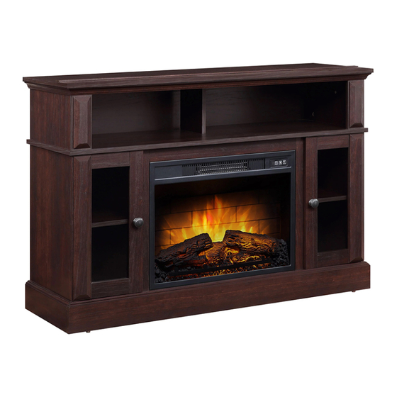
Barston Media Fireplace
MODEL # WMFP48EC-25EP
# WMFP48EC-25DC
# WMFP48EC-25TT
# WMFP48EC-25DP
ADULT ASSEMBLY REQUIRED
www.whalenstyle.com
Or e-mail your request to parts@whalenfurniture.com
PLEASE READ AND KEEP FOR FUTURE REFERENCE.
Date 2023-06-19
866-942-5362
Rev. 0001-A
LOT NUMBER:
DATE PURCHASED:
/
/
Advertisement

Related Manuals for Whalen Barston WMFP48EC-25DC


Summary of Contents for Whalen Barston WMFP48EC-25DC
- Page 1 LOT NUMBER: DATE PURCHASED: Barston Media Fireplace MODEL # WMFP48EC-25EP # WMFP48EC-25DC # WMFP48EC-25TT # WMFP48EC-25DP ADULT ASSEMBLY REQUIRED If you have any questions regarding assembly or if parts are missing, DO NOT return this item to the store where it was purchased. Please call our customer service number and have your instructions and parts list ready to provide the model name, part name or factory number: 866-942-5362 Pacific Standard Time: 8:30 a.m.
-
Page 2: Special Note
G E N E R A L I N F O R M A T I O N , T I P S A N D T R I C K S 1. Please read the Assembly Instructions prior to assembling this product. 2. - Page 3 Important Before you begin: Open, identify and count all parts prior to assembly. Lay out parts on a flat and non- abrasive surface. You will need the parts identified on page 4 and 5 of this instruction manual. NOTE: IT IS VERY IMPORTANT TO USE GLUE WITH DOWELS. EXCESS GLUE CAN BE WIPED OFF WITH DAMP CLOTH.
-
Page 4: Parts And Hardware List
Parts and Hardware List Please read completely through the instructions and verify that all listed parts and hardware are present before beginning assembly. A- Top Panel (Qty. 1) B- Left Lower Side Panel (Qty. 1) C- Right Lower Side Panel (Qty. 1) D- Upper Side Panel (Qty. - Page 5 Parts and Hardware List Please read completely through the instructions and verify that all listed parts and hardware are present before beginning assembly. Fireplace Insert (Qty. 1) Remote Control with Battery (Qty. 1) (1) Cam Lock (2) Cam Bolt (3) M8 x 30 mm Wood Dowel (Qty.
- Page 6 Assembly Instructions ② x 24 1. Unpack the unit and confirm that you have all the hardware and required parts. Assemble the unit on a carpeted floor or the empty carton to avoid any scratch. 2. Securely screw the Cam Bolts (2) into the designated small holes on the Top Panel (A), the Fixed Shelf (G) and the Bottom Panel (M) using a Phillips screwdriver.
- Page 7 Assembly Instructions ② x 16 3. Securely screw the Cam Bolts (2) into the designated small holes on the Upper Side Panel Moldings (F), Lower Side Panels (B and C) and Middle Stiles (K and L) using a Phillips screwdriver.
- Page 8 Assembly Instructions ③ x 12 4. Glue the 30 mm Wood Dowels (3) into side holes of Lower Partition Panels (I and J).
- Page 9 Assembly Instructions ① x 4 5. Align and attach the Left Middle Stile (K) to the Left Lower Partition Panel (I) by engaging 2 Cam Locks (1) (Refer to page 3 on Cam Lock system operation supplement). 6. Repeat the same procedure to combine the Right Middle Stile (L) to the Right Lower Partition Panel (J).
- Page 10 Assembly Instructions ③ x 12 7. Glue the 30 mm Wood Dowels (3) into side holes of Bottom Panel (M) and Bottom Stretchers (N and...
- Page 11 Assembly Instructions ① x 3 8. Align and attach the Bottom Back Stretcher (O) to the Bottom Panel (M) by engaging 3 Cam Locks (1).
- Page 12 Assembly Instructions ① x 4 9. Align and attach the Bottom Front Stretcher (N) to the Bottom Panel (M) by engaging 4 Cam Locks (1).
- Page 13 Assembly Instructions ⑤ x 4 10. Attach the Lower Partition Panels (I and J) to the Bottom Panel (M) with four 50 mm Wood Screws (5).
- Page 14 Assembly Instructions ③ x 6 11. Glue the 30 mm Wood Dowels (3) into side holes of Middle Crossbar (H) and Lower Side Panels (B and C).
- Page 15 Assembly Instructions ① x 3 12. Align and attach the Middle Crossbar (H) to the Fixed Shelf (G) by engaging 3 Cam Locks (1).
- Page 16 Assembly Instructions ① x 8 13. Align the large holes on Left Lower Side Panel (B) with the inserted Wood Dowels (3) on the assembled base. Firmly press them together and fasten it in place by engaging 4 Cam Locks (1). 14.
- Page 17 Assembly Instructions B/C/ I /J ① x 8 15. Ask for assistance to position the Fixed Shelf (G) onto the inserted Wood Dowels (3). Attach the Fixed Shelf (G) in place by engaging 8 Cam Locks (1).
- Page 18 Assembly Instructions ③ x 20 16. Glue the Wood Dowels (3) into side holes of the Upper Panels (D and E) and Upper Side Panel Moldings (F).
- Page 19 Assembly Instructions ① x 4 17. Align and attach one Upper Side Panel Molding (F) to one Upper Side Panel (D) by engaging 2 Cam Locks (1). 18. Repeat the same procedure to combine the other Upper Side Panel Molding (F) to the other Upper Side Panel (D).
- Page 20 Assembly Instructions ② x 6 19. Stand the unit upright. 20. Securely screw the Cam Bolts (2) into the designated small holes on the Fixed Shelf (G) using a Phillips screwdriver.
- Page 21 Assembly Instructions ① x 6 21. Attach the Upper Side Panels assembly to the Fixed Shelf (G) by engaging 4 Cam Locks (1). 22. Fasten the Upper Partition Panel (E) to the Fixed Shelf (G) by engaging 2 Cam Locks (1).
- Page 22 Assembly Instructions ① x 6 23. Ask for assistance to position the Top Panel (A) onto the inserted Wood Dowels (3). Attach the Top Panel (A) in place by engaging 6 Cam Locks (1).
- Page 23 Assembly Instructions ④ x 4 ⑥ x 2 24. Ask for assistance to lay down the assembled unit at its front edges. 25. With pilot holes as a guide, fasten the Middle Crossbar (H) to the Middle Stiles (K and L) by attaching two Metal Brackets (6) at the joints, using two 12 mm Flat Head Screws (4) per Bracket.
- Page 24 Assembly Instructions ⑦ x 36 26. Pick up the Upper Back Panel (R) and align the pre-drilled holes against the upper long edge with the pilot holes on the back stretcher of the Top Panel (A). Attach the Upper Back Panel (R) in place using the provided Washer Head Screws (7).
- Page 25 Assembly Instructions ⑧ x 2 ⑨ x 2 28. Attach one Knob (9) to the front side of each Door (P) with the provided Handle Bolts (8).
- Page 26 Assembly Instructions 29. Stand the unit upright. 30. Pick up one Door (P) and attach the extended hinge arms to the hinge bases installed on the Left Lower Side Panel (B). Loosen the bolt on the back of hinge base for an easy fit. Align and insert the “U” slot on the hinge arm under the bolt head on the back of the hinge base.
- Page 27 Assembly Instructions ⑩ x 8 33. Insert four Shelf Supports (10) into the holes at your desired height inside each side compartment. Tilt and rest the Adjustable Shelves (Q) onto the Shelf Supports (8).
- Page 28 Assembly Instructions 34. Plug the Cam Lock Covers (11) onto the visible Cams Locks to conceal the Cams. 35. Stick the Rubber Bumpers (12) on the outer corners of Doors (P) where they met the Middle Stiles (K and L).
- Page 29 Assembly Instructions 36. Unpack the fireplace insert from the inner box and follow the instructions to install the Top Trim and Side Trims to the fireplace insert. 37. Lift the fireplace insert carefully into the back of the assembled mantel and center it in the opening. DO NOT drag the insert across the Bottom Panel (M) as it may scratch the unit.
- Page 30 Assembly Instructions NOTE: To prevent your TV from tipping, you must follow these instructions if you place a TV on top of your console. Otherwise, skip to “Step 40”. 39. Remove the paper backing from the Stop Rail (T), then properly align the Stop Rail with the top edge of the stopper template on Top Panel (A).
- Page 31 Assembly Instructions Tools required (not provided): Phillips screwdriver, stud finder, power drill and 3 mm/0.1 in drill bit. 41. Ask for assistance to position the assemble fireplace at the desired location against a wall. If necessary, adjust the pre-attached Floor Levelers at the bottom of the unit to level the unit. Now, follow the instructions printed on the plastic bag containing the Tipping Restraint Hardware to attach the tip-over restraints to the unit and the wall.
- Page 32 M A X I M U M R E C O M M E N D E D W E I G H T L O A D S MANUFACTURER: Whalen Furniture Manufacturing CATALOG: Barston Media Fireplace MODEL # WMFP48EC-25EP / WMFP48EC-25DC / WMFP48EC-25TT / WMFP48EC-25DP FITS UP TO MOST 139.7 cm / 55”...
- Page 33 WARNING Please use your furniture correctly and safely. Improper use can cause safety hazards, or damage to your furniture or household items. Carefully read the following safety information. This unit is not intended for use with CRT TVs. The top surface maximum weight capacity is 70 lb (31.8 kg) and maximum load 55in.
-
Page 34: Quality Guarantee
Should this product be defective in workmanship or materials or fail under normal use, we will repair or replace it for up to one (1) year from date of purchase. Every Whalen Furniture product is designed to meet your highest expectations. We guarantee that you will immediately see the value of our fine furniture. - Page 35 NÚMERO de LOTE: FECHA de COMPRA: / Chimenea para Medios Barston Modelo # WMFP48EC-25EP # WMFP48EC-25DC # WMFP48EC-25TT # WMFP48EC-25DP ENSAMBLE REQUERIDO POR ADULTOS Si tiene alguna pregunta relacionada con el montaje o si faltan piezas, NO devuelva este producto al establecimiento donde lo adquirió.
- Page 36 I N F O R M A C I Ó N G E N E R A L , R E C O M E N D A C I O N E S Y T R U C O S 1.
- Page 37 IMPORTANTE Antes de comenzar: Abra, identifique y cuente todas las partes antes del ensamble. Coloque las piezas sobre una superficie plana y no abrasiva. Tendrá que las partes identificadas en la página 4 y 5 de este manual de instrucciones. NOTA: ES MUY IMPORTANTE PARA EL USO DE GOMA CON LOS PERNSO DE MADERA.
- Page 38 Lista de partes y material de ferretería Le rogamos que lea completamente las instrucciones y verifique que todas las piezas y herramientas indicadas se encuentran presentes antes del comienzo del montaje. A- Panel superior (Cant. 1) B- Panel izquierdo inferior (Cant. 1) C- Panel derecho inferior (Cant. 1) D- Panel lateral superior (Cant.
- Page 39 Lista de partes y material de ferretería Le rogamos que lea completamente las instrucciones y verifique que todas las piezas y herramientas indicadas se encuentran presentes antes del comienzo del montaje. Inserto de chimenea (Cant. 1) Control remoto con batería (Cant. 1) (1) Tuerca de fijación (2) Perno de fijación (3) Clavija de madera de M8 x 30 mm...
- Page 40 Instructivo de ensamble ② x 24 1. Desempacar la unidad y confirmar que se tiene todo el material de ferretería y partes requeridas. Ensamblar la unidad en un piso alfombrado o en el cartón vacío para evitar rasguños. 2. Atornillar los pernos de fijación (2) en los agujeros chicos designados en el panel superior (A), la repisa fija (G) y el panel inferior (M) usando el desarmador estrella.
- Page 41 Instructivo de ensamble ② x 16 3. Atornillar los pernos de fijación (2) en los agujeros chicos designados en los montajes del panel lateral superior (F), los paneles laterales inferiores (B y C) y los soportes medios (K y L) usando el desarmador estrella.
- Page 42 Instructivo de ensamble ③ x 12 4. Pegar las clavijas de madera de 30 mm (3) en los agujeros laterales de los paneles divisores inferiores (I y J).
- Page 43 Instructivo de ensamble ① x 4 5. Alinear y adjuntar el soporte medio izquierdo (K) al panel divisor izquierdo inferior (I) empleando 2 tuercas de fijación (1) (Consulte la página 3 del sistema de tuerca de fijación). 6. Repetir el mismo procedimiento para combinar el soporte derecho medio (L) al panel divisor derecho inferior (J).
- Page 44 Instructivo de ensamble ③ x 12 7. Pegar las clavijas de madera de 30 mm (3) en los agujeros laterales del panel inferior (M) y los soportes inferiores (N y O).
- Page 45 Instructivo de ensamble ① x 3 8. Alinear y adjuntar el soporte inferior posterior (O) al panel inferior (M) empleando 3 tuercas de fijación (1).
- Page 46 Instructivo de ensamble ① x 4 9. Alinear y adjuntar el soporte inferior frontal (N) al panel inferior (M) empleando 4 tuercas de fijación (1).
- Page 47 Instructivo de ensamble ⑤ x 4 10. Adjuntar los paneles divisores inferiores (I y J) al panel inferior (M) con 4 pernos para madera de 50 mm (5).
- Page 48 Instructivo de ensamble ③ x 6 11. Pegar las clavijas de madera de 30 mm (3) en los agujeros laterales del soporte medio (H) y los paneles laterales inferiores (B y C).
- Page 49 Instructivo de ensamble ① x 3 12. Alinear y adjuntar el soporte medio (H) a la repisa fija (G) empleando 3 tuercas de fijación (1).
- Page 50 Instructivo de ensamble ① x 8 13. Alinear los agujeros grandes en el panel izquierdo inferior (B) con las clavijas de madera insertadas (3) en la base ensamblada. Presionar para juntar y sujetar en su lugar empleando 4 tuercas de fijación (1). 14.
- Page 51 Instructivo de ensamble B/C/ I /J ① x 8 15. Pedir asistencia para posicionar la repisa fija (G) en las clavijas de madera insertadas (3). Adjuntar la repisa fija (G) en su lugar empleando 8 tuercas de fijación (1).
- Page 52 Instructivo de ensamble ③ x 20 16. Pegar la clavijas de madera (3) en los agujeros laterales de los paneles superiores (D y E).
- Page 53 Instructivo de ensamble ① x 4 17. Alinear y adjuntar un montaje del panel lateral superior (F) a un panel lateral superior (D) empleando 2 tuercas de fijación (1). 18. Repetir el mismo procedimiento para combinar el otro montaje del panel lateral superior (F) al otro panel lateral superior (D).
- Page 54 Instructivo de ensamble ② x 6 19. Poner la unidad en posición vertical. 20. Atornillar los pernos de fijación (2) en los agujeros chicos designados en la repisa fija (G) usando un desarmador estrella.
- Page 55 Instructivo de ensamble ① x 6 21. Adjuntar el ensamble de los paneles laterales superiores a la repisa fija (G) empleando 4 tuercas de fijación (1). 22. Sujetar el panel divisor superior (E) a la repisa fija (G) empleando 2 tuercas de fijación (1).
- Page 56 Instructivo de ensamble ① x 6 23. Pedir asistencia para posicionar el panel superior (A) en las clavijas de madera insertadas (3). Adjuntar el panel superior (A) en su lugar empleando 6 tuercas de fijación (1).
- Page 57 Instructivo de ensamble ④ x 4 ⑥ x 2 24. Pedir asistencia para descansar la unidad ensamblada sobre sus bordes frontales. 25. Con los agujeros pilotos como guía, sujetar el soporte medio (H) a los soportes medios (K y L) empleando 2 soportes de metal (6) en las conexiones, usando 2 pernos de cabeza plana de 12 mm (4) por soporte.
- Page 58 Instructivo de ensamble ⑦ x 36 26. Tomar el panel superior posterior (R) y alinear los agujeros pre-perforados contra el borde superior largo con los agujeros pilotos en el soporte posterior del panel superior (A). Adjuntar el panel superior posterior (R) en su lugar usando los pernos de cabeza de arandela provistos (7). 27.
- Page 59 Instructivo de ensamble ⑧ x 2 ⑨ x 2 28. Adjuntar una jaladera (9) al lado frontal de cada puerta (P) con los pernos de manija provistos (8).
- Page 60 Instructivo de ensamble 29. Poner la unidad en posición vertical. 30. Tomar una puerta (P) y adjuntar los brazos de bisagra extendidos instalados en el panel izquierdo inferior (B). Aflojar el perno en la parte posterior de la base de la bisagra para un encaje fácil. Alinear e insertar el espacio “U”...
- Page 61 Instructivo de ensamble ⑩ x 8 33. Insertar 4 soportes de repisa (10) en los agujeros de su altura deseada adentro de cada compartimiento lateral. Voltear y descansar las repisas ajustables (Q) en los soportes de repisa (8).
- Page 62 Instructivo de ensamble 34. Conectar las tapas de las tuercas de fijación (11) sobre las tuercas de fijación visibles para esconder. 35. Poner los topes de plástico (12) en las esquinas exteriores de las puertas (P) donde se encuentran con los soportes medios (K y L).
- Page 63 Instructivo de ensamble 36. Desempacar el inserto de chimenea de la caja interior y seguir las instrucciones para instalar los bordes superior y laterales al inserto de chimenea. 37. Poner el inserto de chimenea en la parte posterior del mantel ensamblado y centrar en la apertura. arrastre el inserto a través de el panel inferior (F) porque puede rayar la unidad.
- Page 64 Instructivo de ensamble NOTA: Para evitar que su televisor su vuelque, se debe seguir estas instrucciones cuando se ubique su televisor en el mueble. Delo contrario, vaya al paso 40. 39. Retirar el respaldo de papel del riel tope (T), luego alinear el riel tope con el borde superior del templete del tope en el panel superior (A).
- Page 65 Instructivo de ensamble Herramientas necesarias (no incluidas): Desarmador estrella, detector de vigas, taladro eléctrico y taladro de 3mm (0.1"). 41. Pida assistencia para posicionar la chimenea ensamblada en el lugar deseado contra la pared. Si fuera necessario, ajuste los niveladores de piso pre-adjuntados en la parte inferior de la base para nivelar la unidad.
- Page 66 M Á X I M O P E S O R E C O M E N D A D O FABRICANTE: Whalen Furniture Manufacturing CATALOGO: Chimenea para Medios Barston MODELO # WMFP48EC-25EP / WMFP48EC-25DC / WMFP48EC-25TT / WMFP48EC-25DP PARA LA MAYORIA TV’S DE HASTA 139.7 cm / 55”...
- Page 67 ADVERTENCIA Por favor use sus muebles de forma correcta y seguramente. El uso inapropiado puede causar riesgos a la seguridad, o daños a sus muebles u objetos de hogar. Leer cuidadosamente la siguiente información de seguridad. 70 lb (31.8 kg) Esta unidad no debe utilizarse con TVs CRT.
-
Page 68: Mantenimiento Y Cuidados
Si esté producto tiene algun defecto de ensamble o material, o si tiene alguna falla en uso normal, nosotros lo repararemos o lo re-emplazaremos hasta por un año a partir de la fecha de compra. Todo producto de Whalen Furniture es diseñado para alcanzar sus espectativas más altas. Nosotros le garantizamos que inmediatamente podrá...
Need help?
Do you have a question about the Barston WMFP48EC-25DC and is the answer not in the manual?
Questions and answers