Advertisement
Available languages
Available languages
Quick Links
If you have any questions regarding assembly or if parts are missing, DO NOT return this item to the
store where it was purchased. Please call our customer service number and have your instructions
and parts list ready to provide the model name, part name or factory number:
Pacific Standard Time: 8:30 a.m. - 4:30 p.m., Monday - Friday
Or visit our web site 24 hours a day, 7 days a week for product assistance at
THIS INSTRUCTION BOOKLET CONTAINS IMPORTANT SAFETY INFORMATION.
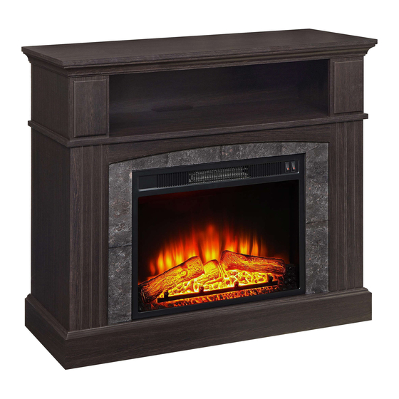
50" Media Fireplace
Stock # WMFP41AE-13
# WMFP41AE-13E
ADULT ASSEMBLY REQUIRED
866-942-5362
www.whalenstyle.com
Or e-mail your request to parts@whalenfurniture.com
PLEASE READ AND KEEP FOR FUTURE REFERENCE.
Date 2018-09-05 Rev. 0001-C
LOT NUMBER:
DATE PURCHASED:
/
/
Advertisement

Related Manuals for Whalen WMFP41AE-13


Summary of Contents for Whalen WMFP41AE-13
- Page 1 LOT NUMBER: DATE PURCHASED: 50" Media Fireplace Stock # WMFP41AE-13 # WMFP41AE-13E ADULT ASSEMBLY REQUIRED If you have any questions regarding assembly or if parts are missing, DO NOT return this item to the store where it was purchased. Please call our customer service number and have your instructions...
-
Page 2: Quality Guarantee
Should this product be defective in workmanship or materials or fail under normal use, we will repair or replace it for up to one (1) year from date of purchase. Every Whalen Furniture product is designed to meet your highest expectations. We guarantee that you will immediately see the value of our fine furniture. - Page 3 IMPORTANT Before you begin: Open, identify and count all parts prior to assembly. Lay out parts on a flat and non- abrasive surface. You will need the parts identified on page 4 and 5 of this instruction manual. NOTE: IT IS VERY IMPORTANT TO USE GLUE WITH DOWELS. EXCESS GLUE CAN BE WIPED OFF WITH DAMP CLOTH.
- Page 4 Parts and Hardware List Please read completely through the instructions and verify that all listed parts and hardware are present before beginning assembly. A- Top Panel (Qty. 1) B- Center Shelf (Qty. 1) C- Bottom Panel (Qty. 1) D- Upper Side Panel E- Upper Front Panel F- Left Lower Side Panel (Qty.
- Page 5 Parts and Hardware List Please read completely through the instructions and verify that all listed parts and hardware are present before beginning assembly. O- Stop Rail (Qty. 1) Fireplace Insert (Qty. 1) (1) Cam Lock (2) Cam Bolt (3) M8 x 30 mm Wood Dowel (Qty.
- Page 6 Assembly Instructions Cam Bolt (18 used in this step) ② 1. Unpack the unit and confirm that you have all the hardware and required parts. Assemble the unit on a carpeted floor or the empty carton to avoid any scratch. 2.
- Page 7 Assembly Instructions Cam Bolt (10 used in this step) ② 3. Securely screw the Cam Bolts (2) into the designated small holes on the Front Panels (E, H and I).
- Page 8 Assembly Instructions Cam Bolt (17 used in this step) ② 4. Securely screw seventeen Cam Bolts (2) into the designated small holes on the Center Shelf (B) on both sides.
- Page 9 Assembly Instructions Cam Lock M8 x 30 mm Wood Dowel (3 used in this step) (2 used in this step) ① ③ 5. Glue two 30 mm Wood Dowels (3) into the inner holes of the Middle Crossbar Assembly (J) and attach it to the Center Shelf (B) by engaging three Cam Locks (1) (Refer to page 3 on Cam Lock system operation supplement).
- Page 10 Assembly Instructions Cam Lock M8 x 30 mm Wood Dowel (3 used in this step) (2 used in this step) ① ③ 6. Attach the Bottom Back Stretcher (M) to the Bottom Panel (C) with two 30 mm Wood Dowels (3) and three Cam Locks (1).
- Page 11 Assembly Instructions Cam Lock (6 used in this step) ① M8 x 30 mm Wood Dowel (4 used in this step) ③ 7. Attach the Left Lower Front Panel (H) to the Left Lower Side Panel (F) with two 30 mm Wood Dowels (3) and three Cam Locks (1).
- Page 12 Assembly Instructions Cam Lock M8 x 30 mm Wood Dowel (6 used in this step) (6 used in this step) ① ③ 9. Attach the Left Lower Side Panel (F) to the Bottom Panel (C) and Bottom Back Stretcher (M) with three 30 mm Wood Dowels (3) and three Cam Locks (1).
- Page 13 Assembly Instructions M4 x 50 mm Screw (4 used in this step) ⑦ 11. Fasten the Lower Front Panels (H and I) to the Bottom Panel (C) with four 50 mm Screws (7).
- Page 14 Assembly Instructions Cam Lock (3 used in this step) ① M8 x 30 mm Wood Dowel (2 used in this step) ③ 12. Attach the Bottom Front Stretcher (L) to the Bottom Panel (C) with two 30 mm Wood Dowels (3) and three Cam Locks (1).
- Page 15 Assembly Instructions M4 x 50 mm Screw (4 used in this step) ⑦ 13. Fasten the Bottom Front Stretcher (L) to the Lower Side Panels (F and G) with four 50 mm Screws (7).
- Page 16 Assembly Instructions M4 x 25 mm Screw M8 x 20 mm Wood Dowel (8 used in this step) (4 used in this step) ⑥ ④ 14. Glue four 20 mm Wood Dowels (4) into the inner holes on the Bottom Front Molding (K) and attach it to the Bottom Front Stretcher (L) with eight 25 mm Screws (6).
- Page 17 Assembly Instructions Cam Lock M8 x 30 mm Wood Dowel (4 used in this step) (6 used in this step) ① ③ 15. Glue six 30 mm Wood Dowels (3) into the inner holes on the vertical panels (F, G, H and I). Position the Center Shelf (B) onto the inserted Wood Dowels (3) and fasten it in place with four Cam Locks (1).
- Page 18 Assembly Instructions Cam Lock M8 x 30 mm Wood Dowel (4 used in this step) (2 used in this step) ① ③ 16. Attach one Upper Front Panel (E) to one Upper Side Panel (D) with two Cam Locks (1) and one Wood Dowel (3).
- Page 19 Assembly Instructions Cam Lock M8 x 30 mm Wood Dowel (6 used in this step) (6 used in this step) ① ③ 18. Attach the Upper Side Panel assemblies to the Top Panel (A) with six 30 mm Wood Dowels (3) and six Cam Locks (1).
- Page 20 Assembly Instructions Cam Lock M8 x 30 mm Wood Dowel (4 used in this step) (6 used in this step) ① ③ 19. Glue six 30 mm Wood Dowels (3) into the inner holes of the Center Shelf (B). Position the Upper Panels (D and E) onto the inserted Wood Dowels (3) and secure them in place with four Cam Locks (1).
- Page 21 Assembly Instructions Cam Lock M3.5 x 12 mm Flat Head Screw (6 used in this step) (4 used in this step) ① ⑤ M4 x 25 mm Metal Bracket Screw (2 used in this step) (2 used in this step) ⑥...
- Page 22 Assembly Instructions M3.5 x 15 mm Washer Head Screw (16 used in this step) ⑧ 24. Now, go back and securely tighten all the Cam Locks and the Screws. Make sure that all the parts are tight and there are no gaps between the parts. This will help keep the unit square. 25.
- Page 23 Assembly Instructions 27. Stand the unit upright. 28. Unpack the fireplace insert from the inner box and follow the instructions to install the Top Trim and Side Trims to the fireplace insert. 29. Lift the fireplace insert carefully into the back of the assembled mantel and center it in the opening. drag the insert across the Bottom Panel (C) as it may scratch the unit.
- Page 24 Assembly Instructions Cam Lock Cover (12 used in this step) ⑩ NOTE: You must install the Strip Stopper to prevent the TV from tipping when placing your flat panel television directly on the console. 31. Remove the paper backing from the Stop Rail (O), then properly align the Stop Rail with the top edge of the stopper template on the Top Panel (A).
- Page 25 Assembly Instructions Tools required (not provided): Phillips screwdriver, stud finder, power drill and 3 mm/0.1 in drill bit. 34. Ask for assistance to position the assembled fireplace at the desired location against a wall. Now, follow the instructions printed on the plastic bag containing the Tipping Restraint Hardware to attach the tip- over restraints to the unit and the wall.
-
Page 26: Care And Maintenance
Care and Maintenance Use a soft, clean cloth that will not scratch the surface when dusting. Use of furniture polishes is not necessary. Should you choose to use polishes, test first in an inconspicuous area. Using solvents of any kind on your furniture may damage the finish. ... - Page 27 LOTE NÚMERO: FECHA DE COMPRA: Chimenea de 50" para media Serie # WMFP41AE-13 # WMFP41AE-13E ENSAMBLE REQUERIDO POR ADULTO Si tienen alguna pregunta acerca del ensamble o si alguna parte está faltante, no retorne este producto a la tienda en donde lo compró. Por favor llame a nuestro departamento de ayuda al cliente teniendo su instructivo y lista de partes para proveer el modelo, nombre de parte o el número de fábrica:...
- Page 28 Si este producto presenta defectos de fabricación ni de materiales o no en condiciones de uso normal, se reparará o reemplazará durante un máximo de un (1) año desde la fecha de compra. Cada producto Whalen Furniture está diseñado para satisfacer sus más altas expectativas. Le garantizamos que usted verá...
- Page 29 IMPORTANTE Antes de comenzar: Abra, identifique y cuente todas las partes antes del ensamble. Coloque las piezas sobre una superficie plana y no abrasiva. Tendrá que las partes identificadas en la página 4 y 5 de este manual de instrucciones. NOTA: ES MUY IMPORTANTE PARA EL USO DE GOMA CON LOS PERNSO DE MADERA.
- Page 30 Partes y lista de material de ferretería Por favor, lea completamente las instrucciones y verifique que todas las partes y material de ferretería enumerados están presentes antes de comenzar el ensamble. A- Panel superior (Cant. 1) B- Repisa central (Cant. 1) C- Panel inferior (Cant.
- Page 31 Partes y lista de material de ferretería Por favor, lea completamente las instrucciones y verifique que todas las partes y material de ferretería enumerados están presentes antes de comenzar el ensamble. O- Riel tope (Cant. 1) Inserto de chimenea (Cant. 1) (1) Tuerca de fijación (2) Tornillo de fijación (3) Perno M8 x 30 mm de madera...
-
Page 32: Instrucciones De Ensamble
Instrucciones de ensamble Tornillo de fijación (18 usados en este paso) ② 1. Desempaque la unidad y confirmar que usted tiene todo el material de ferretería y piezas necesarias. Ensamble la unidad en un lugar o de la caja de cartón vacía para evitar cualquier rasguño. 2. - Page 33 Instrucciones de ensamble Tornillo de fijación (10 usados en este paso) ② 3. Adjuntar de los tornillos de fijación (2) en los orificios pequeños designados en los paneles frontales (E, H e I).
- Page 34 Instrucciones de ensamble Tornillo de fijación (17 usados en este paso) ② 4. Adjuntar de los tornillos de fijación (2) en los orificios pequeños designados en la repisa central (B) en ambos extremos.
- Page 35 Instrucciones de ensamble Tuerca de fijación Perno M8 x 30 mm (3 usados en este paso) (2 usados en este paso) ① ③ 5. Pegar dos pernos de 30 mm de madera (3) en los orificios interiores del soporte central (J) y adjuntarlo a la repisa central (B) mediante la participación de tres tuercas de fijación (1) (Consulte la página 3 del sistema de tuerca de fijación y su funcionamiento).
- Page 36 Instrucciones de ensamble Tuerca de fijación Perno M8 x 30 mm madera (3 usados en este paso) (2 usados en este paso) ① ③ 6. Coloque el soporte posterior (M) al panel inferior (C) con dos pernos de 30 mm de madera (3) y tres tuercas de fijación (1).
- Page 37 Instrucciones de ensamble Tuerca de fijación (6 usados en este paso) ① Perno M8 x 30 mm de madera (4 usados en este paso) ③ 7. Una el panel frontal inferior izquierdo (H) al panel lateral inferior izquierdo (F) con dos pernos de 30 mm de madera (3) y tres tuercas de fijación (1).
- Page 38 Instrucciones de ensamble Tuerca de fijación Perno M8 x 30 mm madera (6 usados en este paso) (6 usados en este paso) ① ③ 9. Una el panel lateral inferior izquierdo (F) al panel inferior (C) y soporte inferior posterior (M) con tres pernos de 30 mm de madera (3) y tres tuercas de fijación (1).
- Page 39 Instrucciones de ensamble Tornillo de M4 x 50 mm (4 usados en este paso) ⑦ 11. Fijar los paneles frontales inferiores (H e I) al panel inferior (C) con cuatro tornillos de 50 mm (7).
- Page 40 Instrucciones de ensamble Tuerca de fijación (3 usados en este paso) ① Perno M8 x 30 mm madera (2 usados en este paso) ③ 12. Coloque el soporte frontal inferior (L) al panel inferior (C) con dos pernos de 30 mm de madera (3) y tres tuercas de fijación (1).
- Page 41 Instrucciones de ensamble Tornillo de M4 x 50 mm (4 usados en este paso) ⑦ 13. Fijar el soporte frontal inferior (L) a los paneles laterales inferiores (F y G) con cuatro tornillos de 50 mm (7).
- Page 42 Instrucciones de ensamble Tornillo M4 x 25 mm Tornillo M8 x 20 mm madera (8 usados en este paso) (4 usados en este paso) ⑥ ④ 14. Pegar cuatro pernos de 20 mm de madera (4) en los orificios internos en la moldura frontal inferior (K) y adjuntarlo al soporte frontal inferior (L) con ocho tornillos de 25 mm (6).
- Page 43 Instrucciones de ensamble Tuerca de fijación Perno M8 x 30 mm madera (4 usados en este paso) (6 usados en este paso) ① ③ 15. Pegar seis pernos de 30 mm de madera (3) en los orificios interiores de los paneles verticales (F, G, H e I).
- Page 44 Instrucciones de ensamble Perno M8 x 30 mm madera Tuerca de fijación (2 usados en este paso) (4 usados en este paso) ③ ① 16. Una un panel frontal superior (E) a un panel lateral superior (D) con dos tuercas de fijación (1) y un perno de madera (3).
- Page 45 Instrucciones de ensamble Tuerca de fijación Perno M8 x 30 mm madera (6 usados en este paso) (6 usados en este paso) ① ③ 18. Coloque los ensambles de panel lateral superior al panel superior (A) con seis pernos de 30 mm de madera (3) y seis tuercas de fijación (1).
- Page 46 Instrucciones de ensamble Tuerca de fijación Perno M8 x 30 mm madera (4 usados en este paso) (6 usados en este paso) ① ③ 19. Insertar seis pernos de 30 mm de madera (3) en los orificios interiores de la repisa central (B). Coloque los paneles superiores (D y E) sobre los pernos de madera insertados (3) y fijarlos en su lugar con cuatro tuercas de fijación (1).
- Page 47 Instrucciones de ensamble Tuerca de fijación Tornillo de M3.5 x 12 mm (6 usados en este paso) cabeza plana (4 usados en este paso) ① ⑤ Tornillo de M4 x 25 mm Soporte de metal (2 usados en este paso) (2 usados en este paso) ⑥...
- Page 48 Instrucciones de ensamble Tornillo de M3.5 x 15 mm cabeza especial (16 usados en este paso) ⑧ 24. Ahora, volver atrás y apriete firmemente todas las tuercas de fijación y los tornillos. Asegúrese de que todas las partes estén apretadas y que no haya espacios entre las partes. Esto ayudará a mantener el cuadrado de la unidad.
- Page 49 Instrucciones de ensamble 27. Poner la unidad en posición vertical. 28. Desempacar el inserto de chimenea de la caja interior y siga las instrucciones para instalar las molduras superiors y laterales de la chimenea. 29. Levante el inserto de la chimenea y con cuidado colocar en la parte posterior de la repisa ensamblada y centrarla en la abertura.
- Page 50 Instrucciones de ensamble Cubierta de tuerca (12 usados en este paso) ⑩ NOTA: Es necesario instalar el riel tope para evitar que el televisor se caiga al ponerle sobre la consola. 31. Retire el papel protector del riel tope (O), y luego alinear correctamente al borde superior de la plantilla para tope en el panel superior (A).
- Page 51 Instrucciones de ensamble (no incluidas): Desarmador estrella, buscador de estudios, taladro y Herramientas adicionales requeridas broca de 3 mm/0.1 pulgadas. 34. Pida ayuda para colocar la unidad ensamblada en el lugar deseado contra una pared. Si es necesario, ajuste los niveladores de piso pre-fijado en la parte inferior de la unidad para nivelar la unidad. Ahora, siga las instrucciones impresas en la bolsa de plástico que contiene el herraje para evitar el vuelco para fijar las restricciones en la unidad y la pared.
-
Page 52: Mantenimiento Y Cuidados
Mantenimiento y Cuidados Use una toalla suave y limpia para evitar daños y rayones. Uso de cera para pulir muebles no es necesario. Si desea usar cera cheque en una area que no sea visible para checar su funcionamiento. ...
Need help?
Do you have a question about the WMFP41AE-13 and is the answer not in the manual?
Questions and answers