Advertisement
Quick Links
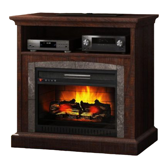
Sheldon 36" Fireplace Console
If you have any questions regarding assembly or if parts are missing, DO NOT return this item to the
store where it was purchased. Please call our toll-free customer service number and have your
instructions and parts list ready to provide the model name, part name or factory number:
THIS INSTRUCTION BOOKLET CONTAINS IMPORTANT SAFETY INFORMATION.
Model # WSF36SH23C
ADULT ASSEMBLY REQUIRED
Pacific Standard Time: 8:30 a.m. - 4:30 p.m., Monday - Friday
Or visit our website www.whalenfurniture.com
Or e-mail your request to:
PLEASE READ AND KEEP FOR FUTURE REFERENCE.
Date 2016-05-18 Rev. 0001-A Factory: DONPEA
# WSF36SH23M
1-866-942-5362
parts@whalenfurniture.com
LOT NUMBER:
DATE PURCHASED: /
/
Advertisement

Related Manuals for Whalen WSF36SH23C


Summary of Contents for Whalen WSF36SH23C
- Page 1 LOT NUMBER: DATE PURCHASED: / Sheldon 36" Fireplace Console Model # WSF36SH23C # WSF36SH23M ADULT ASSEMBLY REQUIRED If you have any questions regarding assembly or if parts are missing, DO NOT return this item to the store where it was purchased. Please call our toll-free customer service number and have your...
-
Page 2: Quality Guarantee
Should this product be defective in workmanship or materials or fail under normal use, we will repair or replace it for up to one (1) year from date of purchase. Every Whalen Furniture product is designed to meet your highest expectations. We guarantee that you will immediately see the value of our fine furniture. - Page 3 Important Before you begin: Open, identify and count all parts prior to assembly. Lay out parts on a flat and non- abrasive surface. You will need the parts identified on page 4 and 5 of this instruction manual. NOTE: IT IS VERY IMPORTANT TO USE GLUE WITH THE DOWELS. EXCESS GLUE CAN BE WIPED OFF WITH A DAMP CLOTH.
-
Page 4: Parts And Hardware List
Parts and Hardware List Please read completely through the instructions and verify that all listed parts and hardware are present before beginning assembly. A- Top Panel (Qty. 1) B- Left Side Panel (Qty. 1) C- Right Side Panel (Qty. 1) D- Fixed Shelf (Qty. - Page 5 Parts and Hardware List Please read completely through the instructions and verify that all listed parts and hardware are present before beginning assembly. (1) Cam Lock (2) Cam Bolt (3) M8 x 30 mm Wood Dowel (Qty. 31+1 extra) (Qty. 31+1 extra) (Qty.
-
Page 6: Assembly Instructions
Assembly Instructions 1. Unpack the unit and confirm that you have all the hardware and required parts. Assembly the unit on a carpeted floor or the empty carton to avoid any scratch. 2. Securely screw the Cam Bolts (2) into the designated small holes on the Top Panel (A), Fixed Shelf (D) and Bottom Panel (E) using a Phillips screwdriver. - Page 7 Assembly Instructions 5. Securely screw the Cam Bolts (2) into the designated small holes on the Side Panels (B and C). 6. Glue two Wood Dowels (3) into the inner holes of the Middle Crossbar (F) and attach to the Fixed Shelf (D) by engaging three Cam Locks (1) (Refer to page 3 on cam lock system operation supplement).
- Page 8 Assembly Instructions 7. Attach the Left and Right Stiles (G and H) to the Fixed Shelf (D) with two Wood Dowels (3) and two Cam Locks (1). 8. Glue four Wood Dowels (3) into the inner holes of Bottom Stretchers (I and J) and attach them to the Bottom Panel (E) with six Cam Locks (1).
- Page 9 Assembly Instructions 9. Attach the assembled Bottom Panel (E) to Left and Right Stiles (G and H) with two Wood Dowels (3) and two 50 mm Screws (5). 10. Glue fourteen Wood Dowels (3) into the inner holes of last assembly at both ends. 11.
- Page 10 Assembly Instructions 12. Fasten the Base Front Stretcher (J) to the Side Panels (B and C) with four 38 mm Screws (6). 13. Attach the Base Front Molding (K) to the Base Front Stretcher (J) with four Wood Dowels (3) and eight 38 mm Screws (6).
- Page 11 Assembly Instructions 14. Glue four Wood Dowels (3) into the top inner holes of the Side Panels (B and C). Position the Top Panel (A) onto the inserted Wood Dowels (3) and fasten it in place with four Cam Locks (1). 15.
- Page 12 Assembly Instructions 17. Pick up the Back Panel (N) and align the pre-drilled holes against the upper long edge with the pilot holes on the back stretcher of Top Panel (A). Attach the Back Panel (N) in place using the provided Washer Head Screws (9).
- Page 13 Assembly Instructions 20. Align and attach the Firebox Support (O) to the Bottom Panel (E) by inserting two 50 mm Self-tapping Screws (4) through the countersunk holes and screw into place. NOTE: You must install the Acrylic TV Stopper to prevent the TV from tipping when placing your flat panel television directly on the console.
- Page 14 Assembly Instructions Tools required: Phillips screwdriver, Power Drill, 3/8” Drill Bit and Rubber Mallet. 24. Ask for assistance to position the assemble fireplace at the desired location against a wall. Now, follow the instructions printed on the plastic bag containing the Tipping Restraint Hardware to attach the tip-over restraints to the unit and the wall.
-
Page 15: Care And Maintenance
Care and Maintenance Use a soft, clean cloth that will not scratch the surface when dusting. Use of furniture polishes is not necessary. Should you choose to use polishes, test first in an inconspicuous area. Using solvents of any kind on your furniture may damage the finish. Never use water to clean your furniture as it may cause damage to the finish.
Need help?
Do you have a question about the WSF36SH23C and is the answer not in the manual?
Questions and answers