Advertisement
Available languages
Available languages
Quick Links
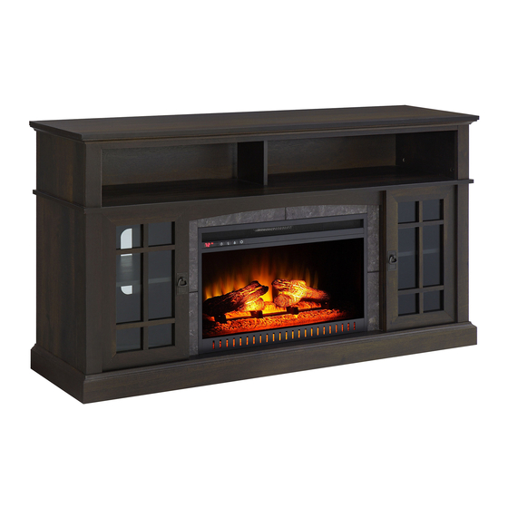
60" Fall Harvest Fireplace
If you have any questions regarding assembly or if parts are missing, DO NOT return this item to the
store where it was purchased. Please call our customer service number and have your instructions
and parts list ready to provide the model name, part name or factory number:
Pacific Standard Time: 8:30 a.m. - 4:30 p.m., Monday - Friday
Or visit our web site 24 hours a day, 7 days a week for product assistance at
THIS INSTRUCTION BOOKLET CONTAINS IMPORTANT SAFETY INFORMATION.
Model # WMFP60FH-14
ADULT ASSEMBLY REQUIRED
www.whalenstyle.com
Or e-mail your request to parts@whalenfurniture.com
PLEASE READ AND KEEP FOR FUTURE REFERENCE.
Date 2017-05-29 Rev. 0001-B Factory: KONRIC
866-942-5362
LOT NUMBER:
DATE PURCHASED: /
/
Advertisement

Related Manuals for Whalen WMFP60FH-14


Summary of Contents for Whalen WMFP60FH-14
- Page 1 LOT NUMBER: DATE PURCHASED: / 60" Fall Harvest Fireplace Model # WMFP60FH-14 ADULT ASSEMBLY REQUIRED If you have any questions regarding assembly or if parts are missing, DO NOT return this item to the store where it was purchased. Please call our customer service number and have your instructions...
- Page 2 M A X I M U M R E C O M M E N D E D W E I G H T L O A D S MANUFACTURER: Whalen Furniture Manufacturing CATALOG: 60" Fall Harvest Fireplace MODEL #: WMFP60FH-14 MADE IN CHINA FITS UP TO MOST 70”...
- Page 3 IMPORTANT Before you begin: Open, identify and count all parts prior to assembly. Lay out parts on a flat and non- abrasive surface. You will need the parts identified on page 4 and 5 of this instruction manual. NOTE: IT IS VERY IMPORTANT TO USE GLUE WITH DOWELS. EXCESS GLUE CAN BE WIPED OFF WITH DAMP CLOTH.
-
Page 4: Parts And Hardware List
Parts and Hardware List Please read completely through the instructions and verify that all listed parts and hardware are present before beginning assembly. A- Top Panel (Qty. 1) B- Center Shelf (Qty. 1) C- Bottom Panel (Qty. 1) D- Bottom Front Molding (Qty. 1) E- Bottom Back Stretcher (Qty. - Page 5 Parts and Hardware List Fireplace Insert (Qty. 1) Remote Control with Battery (Qty. 1) (1) Cam Lock (2) Cam Bolt (3) M8 x 30 mm Wood Dowel (Qty. 43+2 extra) (Qty. 43+2 extra) (Qty. 43+2 extra) (4) M3.5 x 12 mm Flat Head Screw (5) M4 x 25 mm Screw (6) Rubber Bumper (Qty.
- Page 6 Assembly Instructions Cam Bolt (20 used in this step) ② 1. Unpack the unit and confirm that you have all the hardware and required parts. Assembly the unit on a carpeted floor or the empty carton to avoid any scratch. 2.
- Page 7 Assembly Instructions Cam Bolt (17 used in this step) ② 3. Securely screw the Cam Bolts (2) into the designated small holes on the Center Shelf (B) and the Partition Panels (J and H) as shown.
- Page 8 Assembly Instructions Cam Lock Wood Dowel (3 used in this step) (2 used in this step) ① ③ 4. Insert two Wood Dowels (3) into the inner holes of the Middle Crossbar Assembly (L). Tap it in with a rubber mallet, if necessary. Make sure that you use a small amount of glue with both ends of all dowels. 5.
- Page 9 Assembly Instructions Wood Dowel Cam Lock (4 used in this step) (6 used in this step) ③ ① 6. Align and attach the Middle Left Stile (I) to the Left Lower Partition Panel (H) with two 30 mm Wood Dowels (3) and three Cam Locks (1). 7.
- Page 10 Assembly Instructions Wood Dowel Cam Lock (6 used in this step) (8 used in this step) ③ ① 8. Align and attach the Bottom Front Molding (D) to the Bottom Panel (C) by using three Wood Dowels (3) and four Cam Locks (1). 9.
- Page 11 Assembly Instructions Cam Lock Wood Dowel (6 used in this step) (6 used in this step) ① ③ 10. Insert six Wood Dowels (3) into the large holes of the assembled base at both ends. 11. Align the large holes on Left Lower Side Panel (F) with the inserted Wood Dowels (3) on the assembled base.
- Page 12 Assembly Instructions Wood Dowel M4 x 50 mm Wood Screw (4 used in this step) (4 used in this step) ③ ⑦ 13. Insert four Wood Dowels (3) into the inner holes of the Lower Partition Panels (H and J) and attach them to the Bottom Panel (C) by using four 50 mm Wood Screws (7).
- Page 13 Assembly Instructions Cam Lock Wood Dowel (8 used in this step) (8 used in this step) ① ③ 14. Insert eight Wood Dowels (3) into the inner holes on the top edge of the Lower Side Panels (F and G) and Partition Panels (H and J).
- Page 14 Assembly Instructions M3.5 x 12 mm Screw Angle Metal Bracket (8 used in this step) (2 used in this step) ④ ⑪ 16. With the pilot holes as a guide, align and attach two Angle Metal Brackets (11) to the front corners of the assembled base, using four 12 mm Screws (4) per bracket.
- Page 15 Assembly Instructions Floor Leveler (2 used in this step) ⑫ 17. Screw two Floor Levelers (12) into the threaded sockets on the Angle Metal Brackets (11).
- Page 16 Assembly Instructions Cam Bolt (6 used in this step) ② 18. Stand the assembled unit upright. 19. Securely screw six Cam Bolts (2) into the designated small holes on the Center Shelf (B) using a Phillips screwdriver.
- Page 17 Assembly Instructions Cam Lock Wood Dowel (6 used in this step) (5 used in this step) ① ③ 20. Insert five Wood Dowels (3) into the large holes on the Center Shelf (B). Attach the Upper Side Panels (M) and Partition Panel (N) to the Center Shelf (B) by using six Cam Locks (1).
- Page 18 Assembly Instructions M4 x 25 mm Screw Wood Dowel (4 used in this step) (3 used in this step) ⑤ ③ 21. Attach the Top Front Stretcher (T) to the Top Panel (A) with three Wood Dowels (3) and four 25 mm Wood Screws (5).
- Page 19 Assembly Instructions Cam Lock Wood Dowel (6 used in this step) (5 used in this step) ① ③ 22. Insert five Wood Dowels (3) into the top inner holes of the Upper Partition Panel (N) and Side Panels (M). Position the Top Panel (A) onto the inserted Wood Dowels (3) and fasten it in place with six Cam Locks (1).
- Page 20 Assembly Instructions M3.5 x 12 mm Screw Straight Metal Bracket M4 x 25 mm Screw (4 used in this step) (2 used in this step) (2 used in this step) ④ ⑤ ⑨ 23. Fasten the Middle Crossbar Assembly (L) to the Middle Stiles (I and K) by attaching two Straight Metal Brackets (9) at the joints, using two 12 mm Screws (4) per Bracket.
- Page 21 Assembly Instructions M3.5 x 15 mm Washer Head Screw (38 used in this step) ⑧ 25. Pick up the Upper Back Panel (R) and align the pre-drilled holes against the upper long edge with the pilot holes on the back stretcher of the Top Panel (A). Attach the Back Panel (R) in place using the provided Washer Head Screws (8).
- Page 22 Assembly Instructions Shelf Support Cam Lock Cover (8 used in this step) (30 used in this step) ⑩ ⑬ 27. Insert four Shelf Supports (10) into the holes at your desired height inside each side compartment. Tilt and rest the Adjustable Shelves (Q) onto the Shelf Supports (10). 28.
- Page 23 Assembly Instructions Handle and Back Plate Handle Bolt (2 used in this step) (2 used in this step) ⑯ ⑰ 29. Attach one Handle and Back Plate (16) to the front side of each Door (O and P) with the provided Handle Bolt (17).
- Page 24 Assembly Instructions Rubber Bumper (4 used in this step) ⑥ 30. Pick up the Left Door (O) and attach the extended hinge arms to the hinge bases installed on the Left Lower Side Panel (F). Loosen the bolt on the back of Hinge Base for an easy fit. Align and insert the “U”...
- Page 25 Assembly Instructions 34. Lift the Fireplace Insert carefully into the back of the assembled mantel and center it in the opening. drag the insert across the Bottom Panel (C) as it may scratch the unit.
- Page 26 Assembly Instructions L-shaped Metal Bracket M3.5 x 12 mm Pan Head Screw (2 used in this step) (2 used in this step) ⑮ ⑭ 35. Using the pilot holes as a guide, align and attach two L-shaped Metal Brackets (14) to the Bottom Panel (C) by screwing one 12 mm Pan Head Screw (15) in each.
- Page 27 Assembly Instructions NOTE: You must install the Strip Stopper to prevent the TV from tipping when placing your flat panel television directly on the console. 36. Remove the paper backing from the Stop Rail (U), then properly align the Stop Rail with the top edge of the stopper template on Top Panel (A).
- Page 28 Assembly Instructions Tools required: Phillips screwdriver, Power Drill, 3/8” Drill Bit and Rubber Mallet. 38. Ask for assistance to position the assemble fireplace at the desired location against a wall. If necessary, adjust the pre-attached Floor Levelers at the bottom of the Base to level the unit. Now, follow the instructions printed on the plastic bag containing the Tipping Restraint Hardware to attach the tip-over restraints to the unit and the wall.
-
Page 29: Care And Maintenance
Should this product be defective in workmanship or materials or fail under normal use, we will repair or replace it for up to one (1) year from date of purchase. Every Whalen Furniture product is designed to meet your highest expectations. We guarantee that you will immediately see the value of our fine furniture. - Page 31 NÚMERO de LOTE: FECHA de COMPRA: / Chimenea Fall Harvest de 60" Modelo # WMFP60FH-14 ENSAMBLE REQUERIDO POR ADULTO Si tienen alguna pregunta acerca del ensamble o si alguna parte está faltante, no retorne este producto a la tienda donde lo compró. Por favor llame a nuestro departamento de ayuda al cliente teniendo su instructivo y lista de partes para proveer el modelo, nombre de parte o el número de fábrica:...
- Page 32 M Á X I M O P E S O R E C O M E N D A D O FABRICANTE: Whalen Furniture Manufacturing CATALOGO: Chimenea Fall Harvest de 60" MODELO #: WMFP60FH-14 HECHO EN CHINA PARA TVs DE PANTALLA PLANA DE HASTA 70”...
- Page 33 IMPORTANTE Antes de comenzar: Abra, identifique y cuente todas las partes antes del ensamble. Coloque las piezas sobre una superficie plana y no abrasiva. Tendrá que las partes identificadas en la página 4 y 5 de este manual de instrucciones. NOTA: ES MUY IMPORTANTE PARA EL USO DE GOMA CON LOS PERNSO DE MADERA.
- Page 34 Lista de partes y material de ferretería Por favor lea completamente las instrucciones y verifique que estén todas las partes antes de iniciar el ensamblado. A- Panel superior (Cant. 1) B- Repisa central (Cant. 1) C- Panel inferior (Cant. 1) D- Moldura inferior frontal (Cant.
- Page 35 Lista de partes y material de ferretería Inserto de chimenea (Cant. 1) Control remoto con baterías (Cant. 1) (1) Tuerca de fijación (2) Tornillo de fijación (3) Clavija de madera de M8 x 30 mm (Cant. 43+2 extra) (Cant. 43+2 extra) (Cant.
- Page 36 Instructivo de ensamble Tornillo de fijación usados en este paso ② 1. Desempacar la unidad y confirmar que se tiene todo el material de ferretería y partes requeridas. Ensamblar la unidad en un piso alfombrado o en el cartón vacío para evitar rasguños. 2.
- Page 37 Instructivo de ensamble Tornillo de fijación usados en este paso ② 3. Colocar los tornillos de fijación (2) en los agujeros chicos designados en la repisa central (B) y en los paneles divisores (J y H) como se muestra.
- Page 38 Instructivo de ensamble Tuerca de fijación Clavija de madera usados en este paso usados en este paso ① ③ 4. Insertar 2 clavijas de madera (3) en los agujeros interiors del ensamble del soporte medio (L). Golpear ligeramente hacia adentro con el mazo de goma, si fuera necessario. Asegurese de usar poco pegamento para ambos lados de las clavijas de madera.
- Page 39 Instructivo de ensamble Tuerca de fijación Clavija de madera usados en este paso usados en este paso ① ③ 6. Alinear y adjuntar la moldura izquierda media (I) al panel divisor izquierdo inferior (H) con 2 clavijas de madera de 30 mm (3) y 3 tuercas de fijación (1). 7.
- Page 40 Instructivo de ensamble Clavija de madera Tuerca de fijación usados en este paso usados en este paso ③ ① 8. Alinear y adjuntar la moldura inferior frontal (D) al panel inferior (C) usando 3 clavijas de madera (3) y 4 tuercas de fijación (1). 9.
- Page 41 Instructivo de ensamble Tuerca de fijación Clavija de madera usados en este paso usados en este paso ① ③ 10. Insertar 6 clavijas de madera (3) en los agujeros grandes de la base ensamblada en ambos lados. 11. Alinear los agujeros grandes en el panel lateral izquierdo inferior (F) con las clavijas de madera insertadas (3) en la base ensamblada.
- Page 42 Instructivo de ensamble Clavija de madera Tornillo para madera de M4 x 50 mm usados en este paso usados en este paso ③ ⑦ 13. Insertar 4 clavijas de madera (3) en los agujeros interiors de los paneles divisores inferiores (H y J) y adjuntarlos al panel inferior (C) usando 4 tornillos para madera de 50 mm (7).
- Page 43 Instructivo de ensamble Tuerca de fijación Clavija de madera usados en este paso usados en este paso ① ③ 14. Insertar 8 clavijas de madera (3) en los agujeros interiores en el borde superior de los paneles laterales inferiores (F y G) y de los paneles divisores (H y J). 15.
- Page 44 Instructivo de ensamble Tornillo de M3.5 x 12 mm Soporte de metal angular usados en este paso usados en este paso ④ ⑪ 16. Usando los agujeros pilotos como guía, alinear y adjuntar 2 soportes de metal angulares (11) a las esquinas frontales de la base ensamblada, usando 4 tornillos de 12 mm (4) por soporte.
- Page 45 Instructivo de ensamble Nivelador de piso usados en este paso ⑫ 17. Atornillar 2 niveladores de piso (12) en los insertos roscados en los soportes de metal angulares (11).
- Page 46 Instructivo de ensamble Tornillo de fijación usados en este paso ② 18. Poner la unidad ensamblada en posición vertical. 19. Colocar 6 tornillos de fijación (2) en los agujeros chicos designados en la repisa central (B) con un desarmador estrella.
- Page 47 Instructivo de ensamble Tuerca de fijación Clavija de madera usados en este paso usados en este paso ① ③ 20. Insertar 5 clavijas de madera (3) en los agujeros grandes en la repisa central (B). Adjuntar los paneles laterales superiores (M) y el panel divisor (N) a la repisa central (B) usando 6 tornillos de fijación (1).
- Page 48 Instructivo de ensamble Tornillo de M4 x 25 mm Clavija de madera usados en este paso usados en este paso ⑤ ③ 21. Adjuntar el soporte superior frontal (T) al panel superior (A) con 3 clavijas de madera (3) y 4 tornillos para madera de 25 mm (5).
- Page 49 Instructivo de ensamble Tuerca de fijación Clavija de madera usados en este paso usados en este paso ① ③ 22. Insertar 5 pernos de madera (3) en los agujeros superiores interiores del panel divisor superior (N) y de los paneles laterales (M). Posicionar el panel superior (A) sobre las clavijas de madera insertadas (3) y sujetar en su lugar con 6 tuercas de fijación (1).
- Page 50 Instructivo de ensamble Tornillo de M3.5 x 12 mm Soporte de metal recto Tornillo de M4 x 25 mm usados en este paso usados en este paso usados en este paso ④ ⑤ ⑨ 23. Sujetar el ensamble del soporte medio (L) a las molduras medias (I y K) adjuntado 2 soportes de metal rectos (9) en las conexiónes, usando 2 tornillos de 12 mm (4) por soporte.
- Page 51 Instructivo de ensamble Tornillo cabeza de arandela de M3.5 x 15 mm usados en este paso ⑧ 25. Tomar el panel superior posterior (R) y alinear los agujeros pre-perforados encontra del borde superior largo con los agujeros pilotos del soporte posterior del panel superior (A). Adjuntar el panel posterior (R) en su lugar usando los tornillos cabeza de arandela (8).
- Page 52 Instructivo de ensamble Soporte de repisa Tapa de la tuerca de fijación usados en este paso usados en este paso ⑩ ⑬ 27. Insertar 4 soportes de repisa (10) en los agujeros de su altura deseada adentro de cada compartimiento. Voltear y descansar las repisas ajustables (Q) en los soportes de repisa (10).
- Page 53 Instructivo de ensamble Manija y placa posterior Tornillo de manija usados en este paso usados en este paso ⑯ ⑰ 29. Adjuntar una manija y placa posterior (16) a la parte frontal de cada puerta (O y P) con el tornillo de manija (17).
- Page 54 Instructivo de ensamble Tope de plástico usados en este paso ⑥ 30. Tomar la puerta izquierda (O) y adjuntar los brazos de bisagras extendidos a las bases de bisagra instaladas en el panel lateral izquierdo inferior (F). Aflojar el tornillo detrás de la base para un ajuste fácíl.
- Page 55 Instructivo de ensamble 34. Poner el inserto de chimenea en la parte posterior del mantel ensamblado y centrar en la apertura. arrastre el inserto a través de el panel inferior (C) porque puede rayar la unidad.
- Page 56 Instructivo de ensamble Abrazadera de metal “L” Tornillo cabeza redonda de M3.5 x 12 mm usados en este paso usados en este paso ⑭ ⑮ 35. Usando los agujeros pilotos como guía, alinear y adjuntar 2 abrazaderas de metal “L” (14) al panel inferior (C) atornillando un tornillo cabeza redonda de 12 mm (15) en cada una.
- Page 57 Instructivo de ensamble NOTA: Debe instalar el tope acrílico de TV para prevenir la TV de inclinarse cuando ponga su televisión de pantalla plana directamente sobre la consola. 36. Retirar el respaldo de papel del riel tope (U), luego alinear el riel tope con el borde superior del templete del tope en el panel superior (A).
- Page 58 Instructivo de ensamble Herramientas requeridas: Desarmador estrella, taladro, broca de 3/8” y mazo de goma. 38. Pida assistencia para posicionar la chimenea ensamblada en el lugar deseado contra la pared. Si fuera necessario, ajuste los niveladores de piso pre-adjuntados en la parte inferior de la base para nivelar la unidad.
-
Page 59: Mantenimiento Y Cuidados
Si esté producto tiene algun defecto de ensamble o material, o si tiene alguna falla en uso normal, nosotros lo repararemos o lo re-emplazaremos hasta por un año a partir de la fecha de compra. Todo producto de Whalen Furniture es diseñado para alcanzar sus espectativas más altas. Nosotros le garantizamos que inmediatamente podrá...
Need help?
Do you have a question about the WMFP60FH-14 and is the answer not in the manual?
Questions and answers