Table of Contents
Advertisement
Quick Links
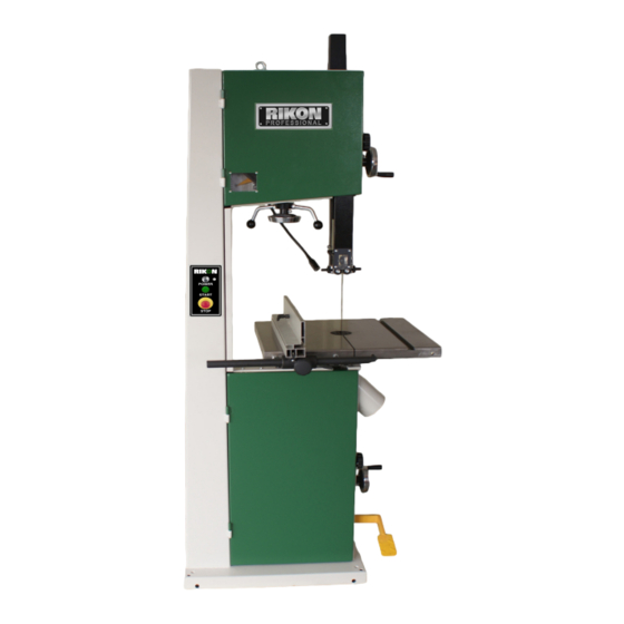
14" Professional Bandsaw
Models: 10-350/10-350BAL
Record the serial number and date of purchase
in your manual for future reference.
Serial number:
Date of purchase:
For more information:
www.rikontools.com
info@rikontools.com
or
For Parts or Questions:
techsupport@rikontools.com
877-884-5167
or
Part #10-350M1
Advertisement
Table of Contents

Subscribe to Our Youtube Channel
Related Manuals for Rikon Power Tools 10-350


Summary of Contents for Rikon Power Tools 10-350
- Page 1 14” Professional Bandsaw Models: 10-350/10-350BAL Record the serial number and date of purchase in your manual for future reference. Serial number: Date of purchase: For more information: www.rikontools.com info@rikontools.com For Parts or Questions: techsupport@rikontools.com 877-884-5167 Part #10-350M1...
-
Page 2: Safety Warnings
Operator Safety: Required Reading IMPORTANT! Safety is the single most important consideration in the operation of this equipment. The following instructions must be followed at all times. There are certain applications for which this tool was designed. We strongly recommend that this tool not be modified and/ or used for any other application other than that for which it was designed. -
Page 3: Bandsaw Safety Rules
ALWAYS DISCONNECT TOOLS. Disconnect tools before servicing and when changing accessories such as blades, bits, and cutters. ALWAYS AVOID ACCIDENTAL STARTING. Make sure switch is in “OFF” position before plugging in cord. NEVER LEAVE TOOLS RUNNING UNATTENDED. ALWAYS CHECK FOR DAMAGED PARTS. Before initial or continual use of the tool, a guard or other part that is damaged should be checked to assure that it will operate properly and perform its intended function. -
Page 4: Table Of Contents
Troubleshooting .........................18-19 Changing Bandsaw Tire ..........................19 Adjusting Fence 90 Degrees to the Table........................19 Parts Diagrams/Lists ..........................20-29 How To Guide .............................30 Warranty .............................31 Specifications 10-350 10-350BAL Throat Width 13-9/16” (345 mm) Throat width 13-9/16” (345 mm) Max. Cutting Depth 13-15/16” (356 mm) Max. -
Page 5: Contents Of Package
Contents of Package Model 10-350 14” Professional Bandsaw is shipped complete in one crate. Model 10-350BAL is shipped in two cartons unless otherwise noted. Unpacking and Checking Contents a. Separate all “loose parts” from packaging materials and check each item with “Table of Loose Parts”... -
Page 6: Loose Parts
Loose Parts List LIST OF LOOSE PARTS Table assembly: A. Table B. Table leveling bar and hardware C. 90° table stop bolt D. Table mounting bolts and washers Rip fence assembly: A. Fence bar B. Fence C. Fence carrier D. Resaw bar Tool holder assembly: A. -
Page 7: Getting To Know Your Bandsaw
Getting to Know Your Bandsaw A. Hoist Ring L. Work Table B. Tension Indicator Window M. Drive Belt Tension Wheel C. Blade Tension Hand-Wheel N. 4” Dust Ports D. Switch O. Foot Break E. Rip Fence P. Blade Tracking Knob F. -
Page 8: Rip Fence Assembly
Hand Wheel Installation There are two hand wheels used on the 10-350 bandsaw. The first controls the height of the upper guide post, the second adds/removes tension on the drive Figure 3 belt. -
Page 9: Setting
Assembly Adjustments Storage for the “L” wrenches is provided for quick Tool Holder access when adjustments are needed. Place the (4) “L” wrenches (3mm, 4mm, 5mm and 6mm) in the tool holder on the rear column support (Fig.5). Setting the Table Square to Saw Blade The table may be set at 90°... -
Page 10: Tracking Blade
Finally, tighten the lock lever and close the doors. Adjusting the Blade Tension The 10-350 has a quick release blade function which allows for fast blade changing and tensioning. The quick release lever is shown in figure 10. -
Page 11: Changing The Bandsaw Blade
Adjustments Changing the Bandsaw Blade Warning! Unplug the machine from the electrical supply. This ensures that the Bandsaw will not accidentally turn on if the ON/OFF switch is bumped. a) Open the top and bottom wheel doors by turning the door locking knobs. (A-Fig.13) b) Release the blade tension by moving the quick release lever (Fig.14) from right to left. -
Page 12: Upper Blade Guide Adjustment
Adjusting the Blade Guides Upper Guides: To adjust the upper blade guides, first position the roller guides relative to the blade by loosening the Allen cap head screw (A-Fig.17) and sliding the guide assembly until the side roller guides are approximately 1/16” behind the gullet of the blade then tighten the Allen cap head screw (A-Fig.17). -
Page 13: Changing Blade Speed
Operation Switch Control Station Figure 22 The 10-350 has a key-on safety feature that will lock out unauthorized users such as students, coworkers or employees not trained or qualified to use the bandsaw. To operate the saw turn the key (A-Fig.23) to the right to activate the control station. - Page 14 Adjusting the Rip Fence/Drift Align the fence assembly in or out until parallel with the side of the blade by turning the adjustment collars and the fence bolts accordingly (A-Fig.24). If the mounting bolts have been tightened, these will need loosened off before this adjustment can be made.
- Page 15 Foot Brake The foot brake, when depressed will slow the blade to a stop. The foot brake (A-Fig.27) on the 10-350 will also shut off the bandsaw simultaneously. This is an added safety feature that allows you to handle large workpieces without having to reach back to the switch control station to the main “STOP”...
-
Page 16: Electrical Requirements
Electrical Requirements In the event of a malfunction or breakdown, grounding provides a path of least resistance for electric current to reduce the risk of electric shock. This tool is equipped with an electric cord having an equipment-grounding conductor and a grounding plug. The plug must be plugged into a matching outlet that is properly installed and grounded in accordance with all local codes and ordinances. -
Page 17: Maintenance
Maintenance Caution! BEFORE CLEANING OR CARRYING OUT MAINTENANCE WORK, DISCONNECT THE MACHINE FROM THE POWER SOURCE (WALL SOCKET). NEVER USE WATER OR OTHER LIQUIDS TO CLEAN THE MACHINE. USE A BENCH BRUSH. DO NOT USE COMPRESSED AIR NEAR BEARINGS. REGULAR MAINTENANCE OF THE MACHINE WILL PREVENT UNNECESSARY PROBLEMS. -
Page 18: Troubleshooting
Troubleshooting WARNING! FOR YOUR OWN SAFETY, ALWAYS TURN OFF AND UNPLUG THE MACHINE BEFORE CARRYING OUT ANY TROUBLESHOOTING. TROUBLE PROBABLE CAUSE REMEDY The machine does not 1. No power supply. Check the cable for breakage. work when switched on. 2. Defective switch. Contact your local dealer for repair. -
Page 19: Changing Bandsaw Tire
Troubleshooting Adjusting the Upper Blade Guide Bearings Parallel to the Blade (Refer to “Guide Post Assembly” parts diagram on page 28) This step may not be necessary, it is factory preset. If adjustment is needed follow the steps below. First slightly loosen part #226 Hex Bolt M8X20 (4 each) on rear of upper bandsaw housing. This will allow you to adjust the micro adjustment screws #227 in part #224 Gear Bracket. -
Page 20: Parts Diagrams/Lists
Parts Diagram Frame Assembly... - Page 21 Parts List Frame Assembly Key No. Part No. Description Key No. Part No. Description M8X16GB825Z Ring WSH6GB96Z Washer ST3D5X19GB845Z Tap screw M6X16GB5783Z Bolt M6X16 WSH4GB96Z Washer M6GB889Z Locking nut JL20073003 Micro-switch cap M6X25GB5783Z Hex bolt M6X25 KW3-0Z-2B Switch JL26010003 Brush JL20073002 Micro-switch cover WSH6GB96Z...
- Page 22 Parts Diagram Wheel Assembly...
- Page 23 Parts List Wheel Assembly Key No. Part No. Description WSH8GB96Z Washer M8X16GB70Z Hex socket screw M8X16 JMBS1402020001 Blade JMBS1402022100 Lower wheel assm. JL28020004 Bushing JL21022002A Tire CLP40GB893D1B Retaining ring BRG180203GB278 Bearing JL28022001 Upper wheel...
- Page 24 Parts Diagram Table & Fence Assembly...
- Page 25 Parts List Table & Fence Assembly Key No. Part No. Description Key No. Part No. Description JMBS1602060001 Rip fence WSH10GB97D1Z Washer JMBS1601060002 Locking Plate M12X30GB5781B Screw M12X30 WSH6GB97D1Z Washer WSH12GB97D1B Washer WSH6GB93Z Spring washer WSH12GB93B Spring washer M6X16GB70Z Hex socket screw M6X16 JL26050002B Lower table trunnion JL20024001...
- Page 26 Parts Diagram Blade Tension/Tracking...
- Page 27 Parts List Blade Tension/Tracking Key No. Part No. Description M10GB6170Z Hex nut M10 WSH10GB93B Spring washer M12GB923Z Nut M12 WSH12GB93B Spring washer M10GB889Z Locking nut WSH10GB97D1Z Flat washer JXBS1801030006 Bolt JXBS1801030007 Threaded rod JXBS1401030002 Slide rod JMBS1402040011 Upper wheel shaft JMBS1402040010 Bushing JMBS1402040001...
- Page 28 Parts Diagram Guide Post Assembly...
- Page 29 Parts List Guide Post Assembly Key No. Part No. Description JMBS1402050001 Guide post JMBS1402050002 Rack M4X10GB819Z Pan head screw JL26040002 Cover M8X10GB70Z Hex socket screw M8X10 JMBS1402052000 Blade cover JL26040006 Screw 1501006 Gear M4X8GB818Z Pan head screw JL26042011 Spectator M4GB6170Z Hex nut M4 M6X30GB70Z Hex socket screw M6X30...
-
Page 31: Warranty
Warranty 5-Year Limited Warranty RIKON Power Tools Inc. (“Seller”) warrants to only the original retail consumer/purchaser of our products that each product be free from defects in materials and workmanship for a period of five (5) years from the date the product was purchased at retail. This warranty may not be transferred. - Page 32 For more information: 16 Progress Rd Billerica, MA 01821 877-884-5167/978-528-5380 techsupport@rikontools.com www.rikontools.com Copyright RIKON Power Tools Inc. 2012 Printed in China 3/12...
Need help?
Do you have a question about the 10-350 and is the answer not in the manual?
Questions and answers