Table of Contents
Advertisement
Quick Links
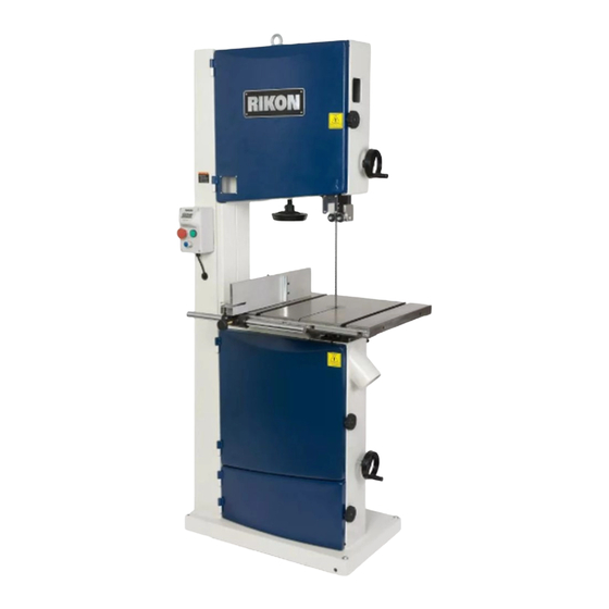
10-370
18" Wood/Metal Bandsaw
4001824
Shown with optional
Mobility Kit 13-345
Operator's Manual
Record the serial number and date of purchase in your manual for future reference.
The serial number can be found on the specification label on the rear of your machine.
Serial Number: _________________________
Date of purchase: _________________________
For technical support or parts questions, email techsupport@rikontools.com or call toll free at (877)884-5167
www.rikontools.com
10-370M3
Advertisement
Table of Contents

Related Manuals for Rikon Power Tools 10-370


Summary of Contents for Rikon Power Tools 10-370
- Page 1 10-370 18” Wood/Metal Bandsaw 4001824 Shown with optional Mobility Kit 13-345 Operator’s Manual Record the serial number and date of purchase in your manual for future reference. The serial number can be found on the specification label on the rear of your machine.
-
Page 2: Table Of Contents
Changes and improvements may be made at any time, with no obligation on the part of Rikon Power Tools, Inc. to modify previously delivered units. Reasonable care has been taken to ensure that the information in this manual is correct, to provide you with the guidelines for the proper safety,... -
Page 3: Safety Instructions
SAFETY INSTRUCTIONS IMPORTANT! Safety is the single most important consideration in the operation of this equipment. The following instructions must be followed at all times. Failure to follow all instructions listed below may result in electric shock, fire, and/or serious personal injury. There are certain applications for which this tool was designed. - Page 4 SAFETY INSTRUCTIONS 12. KEEP PROTECTIVE GUARDS IN PLACE AND IN 25. ALWAYS WEAR A DUST MASK TO PREVENT WORKING ORDER. INHALING DANGEROUS DUST OR AIRBORNE PARTICLES, including wood dust, crystalline silica dust 13. AVOID ACCIDENTAL STARTING. Make sure that and asbestos dust. Direct particles away from face and the power switch is in the “OFF”...
-
Page 5: Electricals & Wiring Diagram
SAFETY INSTRUCTIONS ELECTRICAL SAFETY EXTENSION CORDS THIS TOOL MUST BE GROUNDED THE USE OF AN EXTENSION CORD WITH THIS MACHINE IS NOT RECOMMENDED. For WHILE IN USE TO PROTECT THE OPERATOR FROM ELECTRIC SHOCK. best power and safety, plug the machine directly into a dedicated, grounded electrical outlet that is within the IN THE EVENT OF A MALFUNCTION OR BREAKDOWN, supplied cord length of the machine. - Page 6 SAFETY INSTRUCTIONS SPECIFIC SAFETY INSTRUCTIONS FOR BAND SAWS This machine is intended for the cutting of natural, solid woods, composite materials, plastics and non-ferrus metals. The permissible workpiece dimensions must be observed (see Technical Specification). Any other use not as specified, including modification of the machine or use of parts not tested and approved by the equipment manufacturer, can cause unforeseen damage and invalidate the warranty.
-
Page 7: Contents Of Package
CONTENTS OF PACKAGE Model 10-370 18” Wood/Metal Bandsaw is shipped complete in one crate. Unpacking, Checking Contents & Clean-up 1. Carefully remove all contents from the shipping carton. Compare the contents with the list of contents to make sure that all of the items are accounted for, before discarding any packing material. Place parts on a protected surface for easy identification and assembly. - Page 8 LOOSE PARTS LIST LIST OF LOOSE PARTS Table Assembly: A. Table B. Table leveling bar and hardware may be pre-assembled on the table C. 90° Table stop bolt D. Table mounting bolts and washers Rip Fence Assembly: A. Fence bar and hardware B.
-
Page 9: Getting To Know Your Machine
GETTING TO KNOW YOUR MACHINE A. Ring - J. Drive Belt Tension Wheel to secure saw during transport B. Tension Indicator Window K. 4” Dust Ports C. Blade Tension Hand Wheel L. Blade Tracking Knob D. On/Off Switch M. Quick Release Lever E. -
Page 10: Assembly
ASSEMBLY The 10-370 Bandsaw is supplied partly assembled. Prior to use, the following items have to be assembled: switch, working table, rip fence and hand wheels. Warning! To ensure sufficient upright stability and safety of this bandsaw, you need to bolt the bandsaw to... - Page 11 ASSEMBLY Installing the Switch Box - continued 3. Mount the switch to the front of the band saw column by using the corresponding holes in the back of the switch box. FIG. 4, A. Use the same two screws that were removed from the frame shown in Fig.
- Page 12 HAND WHEEL INSTALLATION bandsaw, with the 5mm “L” wrench. FIG. 9. There are two hand wheels used on the 10-370 Wood/Metal Bandsaw. The first controls 2. Then, attach the second crank handle (#21E) the height of the upper guide post, the second to the belt and speed control rod located on the controls the tension on the drive belt.
-
Page 13: Adjustments
ASSEMBLY TOOL STORAGE Storage for the “L” hex wrenches is provided for Tool Holder quick access when adjustments are needed. Mount the tool holder onto the rear column with the two screws provided (#40A, 41A). Place the (4) hex wrenches (3, 4, 5 and 6mm) in the tool holder on the rear column support. - Page 14 Finally, tighten the lock lever and close the doors. Quick Release ADJUSTING THE BLADE TENSION The 10-370 has a quick release blade function which allows for fast blade changing and tensioning. The quick release lever extends from the rear of the saw. FIG. 15.
- Page 15 ADJUSTMENTS CHANGING THE SAW BLADE THE MACHINE MUST NOT BE PLUGGED IN AND THE POWER SWITCH MUST BE IN THE OFF POSITION UNTIL ALL 1. Open the top and bottom wheel doors by ADJUSTMENTS ARE COMPLETE. turning the door locking knobs (#12A). FIG. 18, A. 2.
- Page 16 ADJUSTMENTS ADJUSTING THE BLADE GUIDES Upper Guides: 1. Position the roller guides relative to the blade by loosening the locking hex screw (#42C, FIG. 21, A) and moving the guide carrier until the roller guides are approximately 1/16” behind the gullets of the bandsaw blade, then tighten the UPPER hex nut to set the bearings in place.
- Page 17 FIG. 24. CHANGING THE BLADE SPEED PULLEY SETTINGS Approximately 1/4” The 10-370 has two pulley speed ranges; FIG. 24 - Low Speed - 82-1312 ft/min - High Speed - 328-3280 ft/min THE MACHINE MUST NOT BE...
- Page 18 ADJUSTMENTS VARIABLE SPEED SWITCH In conjunction with the two speed pulley system, the 10-370 Wood/ Metal bandsaw also features a variable speed switch. To use with in a specific belt speed range, simply turn the bandsaw on (FIG. 28, A)and rotate the variable speed dial (B) clockwise to increase the speed, and counter clockwise to decrease the speed.
-
Page 19: Operation
METAL CUTTING Warning! The 10-370 Wood/Metal bandsaw is designed for DRY CUTTING ONLY. Do not use lubricants or coolants with this bandsaw. Proper blade selection for the material to be cut is key to good performance. Do not force the material into the blade as excessive heat will lead to premature blade failure. - Page 20 OPERATION Cutting Plastic/Composite Material The 10-370 Wood/Metal bandsaw is also designed for cutting plastics and composite materials. As always, selecting the proper blade for the material to be cut is key to getting good performance. Do not force the material into the blade as excessive heat will lead to premature blade failure and poor cutting results will also occur.
-
Page 21: Maintenance
MAINTENANCE Caution! BEFORE CLEANING OR CARRYING OUT MAINTENANCE WORK, DISCONNECT THE MACHINE FROM THE POWER SOURCE (WALL SOCKET). NEVER USE WATER OR OTHER LIQUIDS TO CLEAN THE MACHINE. USE A BENCH BRUSH. DO NOT USE COMPRESSED AIR NEAR BEARINGS. REGULAR MAINTENANCE OF THE MACHINE WILL PREVENT UNNECESSARY PROBLEMS. -
Page 22: Troubleshooting
TROUBLESHOOTING FOR YOUR OWN SAFETY, ALWAYS TURN OFF AND UNPLUG THE MACHINE BEFORE CARRYING OUT ANY TROUBLESHOOTING OR ADJUSTMENTS. TROUBLE PROBABLE CAUSE REMEDY The machine does not 1. No power supply. Check the cable for breakage. work when switched on. 2. - Page 23 TROUBLESHOOTING THE MACHINE MUST NOT BE PLUGGED IN AND THE POWER SWITCH MUST BE IN THE OFF POSITION UNTIL ALL ADJUSTMENTS ARE COMPLETE. ADJUSTING THE UPPER GUIDE BEARINGS PARALLEL TO THE BLADE The guide bearing assembly is factory pre-set. If adjustment is needed, follow the steps below. Refer to “Guide Post Assembly”...
- Page 24 TROUBLESHOOTING LOWER WHEEL ADJUSTMENTS The following instructions will correct common blade issues related to the lower wheel’s alignment in relation to the upper wheel. These adjustments will correct the blade position on the lower wheel and blade oscillation (wobble). These are critical adjustments which affect the performance and accuracy of the bandsaw.
- Page 25 TROUBLESHOOTING If a blade is tracking on the rear of the lower wheel , away from the door, follow these steps: De-tension the saw blade. Loosen 9 o’clock shaft bolt to take pressure off the shaft. Loosen 6 o’clock shaft bolt one half rotation. Tighten the 12 o’clock shaft bolt until the shaft touches the 6 o’clock adjusting bolt.
-
Page 26: Parts Diagrams & Parts Lists
PARTS DIAGRAM FRAME ASSEMBLY (A) 9 19 NOTE: Please reference the Manufacturer’s Part Number when calling for Replacement Parts. For Parts under Warranty, the serial number of your machine is required. - Page 27 PARTS LIST KEY NO. DESCRIPTION MFG. PART NO. QTY. Frame P10-370-1A Lifting bolt P10-370-2A Inverter box P10-370-3A Indicator adjustment plate P10-370-4A Cross recess pan head screw M5X8 P10-370-5A Screw P10-370-6A Blade tension indicator P10-370-7A Upper wheel cover P10-370-8A Plastic window P10-370-9A Self-plugging rivet P10-370-10A...
- Page 28 PARTS DIAGRAM TABLE ASSEMBLY (B) 14 15 20 21 43 44 37 38 39 40 41...
- Page 29 PARTS LIST TABLE ASSEMBLY (B) MFG. MFG. DESCRIPTION PART NO. QTY. DESCRIPTION PART NO. QTY. P10-370-1B P10-370-41B Fence Hex screw M8X25 Lock plate P10-370-2B Thin nut P10-370-42B P10-370-3B P10-370-43B Adjustable base Thin nut Flat washer P10-370-4B Tube P10-370-44B Handle P10-370-5B Handle P10-370-45B P10-370-6B...
- Page 30 PARTS DIAGRAM GUIDE ASSEMBLY (C) NOTE: Please reference the Manufacturer’s Part Number when calling for Replacement Parts. For Parts under Warranty, the serial number of your machine is required.
- Page 31 PARTS LIST GUIDE ASSEMBLY C) KEY NO. DESCRIPTION MFG. PART NO. QTY. P10-370-1C Blade guard assembly P10-370-2C Flat washer P10-370-3C Hex socket cap screws M5X12 P10-370-4C Hex socket cap screws M8X40 P10-370-5C Bearing 6201 P10-370-6C Tube P10-370-7C Tube P10-370-8C Upper guide body P10-370-9C Hex socket cap screws M8X30...
- Page 32 PARTS DIAGRAM BLADE TENSION & TRACKING (D)
- Page 33 PARTS LIST BLADE TENSION & TRACKING (D) KEY NO. DESCRIPTION MFG. PART NO. QTY. Sliding rail P10-370-1D Upper wheel shaft hinge P10-370-2D Roll pin P10-370-3D Upper wheel shaft P10-370-4D Bushing P10-370-5D Support shaft P10-370-6D Big washer P10-370-7D Screw M8X10 P10-370-8D Shaft hinge P10-370-9D Bearing...
- Page 34 PARTS DIAGRAM DRIVE ASSEMBLY (E) 9 10 36 37 NOTE: Please reference the Manufacturer’s Part Number when calling for Replacement Parts. For Parts under Warranty, the serial number of your machine is required.
- Page 35 PARTS LIST DRIVE ASSEMBLY (E) KEY NO. DESCRIPTION MFG. PART NO. QTY. P10-370-1E Rubber tire P10-370-2E Hex bolt M8X16 P10-370-3E Big washer P10-370-4E Retaining ring P10-370-5E Bearing 6204 P10-370-6E Tube P10-370-7E Upper wheel P10-370-8E Lower wheel P10-370-9E M27X2 P10-370-10E Washer P10-370-11E Hex socket cap screws M8X25...
-
Page 36: How To' Guide For All Band Saw Blades
BANDSAW BLADE GUIDE... -
Page 37: Accessories
ACCESSORIES NOTES C10-391 TABLE INSERTS - PACK OF 4 C10-395 ALUMINUM TABLE INSERT 13-912 ‘T’ SLOT MITER GAUGE C10-392 ZERO CLEARANCE INSERTS - PK 4 13-345 MOBILITY KIT 12-201 MAGNETIC BASE LED WORKLIGHT BAND SAW BLADES For a complete line of 142” band saw blades, contact you local RIKON distributor, or visit the RIKON website at www.rikontools.com. - Page 38 NOTES Use this section to record maintenance, service and any calls to Technical Support:...
-
Page 39: Warranty
® 5-Year Limited Warranty RIKON Power Tools Inc. (“Seller”) warrants to only the original retail consumer/purchaser of our products that each product be free from defects in materials and workmanship for a period of five (5) years from the date the product was purchased at retail. This warranty may not be transferred. - Page 40 10-370 For more information: 16 Progress Road Billerica, MA 01821 877-884-5167 / 978-528-5380 techsupport@rikontools.com www.rikontools.com 10-370M3...
Need help?
Do you have a question about the 10-370 and is the answer not in the manual?
Questions and answers