Table of Contents
Advertisement
Quick Links
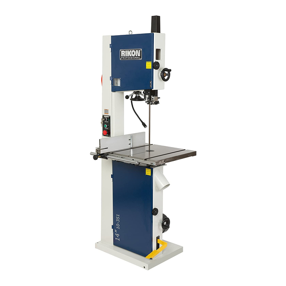
10-351
14" Professional Bandsaw
4001824
Operator's Manual
Record the serial number and date of purchase in your manual for future reference.
Serial Number: _________________________
Date of purchase: _________________________
For technical support or parts questions, email techsupport@rikontools.com or call toll free at (877)884-5167
www.rikontools.com
10-351M1
Advertisement
Table of Contents

Related Manuals for Rikon Power Tools 10-351


Summary of Contents for Rikon Power Tools 10-351
- Page 1 10-351 14” Professional Bandsaw 4001824 Operator’s Manual Record the serial number and date of purchase in your manual for future reference. Serial Number: _________________________ Date of purchase: _________________________ For technical support or parts questions, email techsupport@rikontools.com or call toll free at (877)884-5167 www.rikontools.com...
-
Page 2: Table Of Contents
Wiring Diagram ........................18 Notes ..........................20 Troubleshooting ......................19 - 23 Parts Explosions & Parts Lists ..................24 - 33 How To Guide for all Band Saw Blades ..................34 Warranty ..........................35 SPECIFICATIONS Model No. 10-351 Motor Horsepower 3 HP Amps 12.9 Volts 220V, 60 Hz... -
Page 3: Safety Instructions
SAFETY INSTRUCTIONS IMPORTANT! Safety is the single most important consideration in the operation of this equipment. The following instructions must be followed at all times. Failure to follow all instructions listed below may result in electric shock, fire, and/or serious personal injury. There are certain applications for which this tool was designed. - Page 4 SAFETY INSTRUCTIONS 12. KEEP PROTECTIVE GUARDS IN PLACE AND IN 25. ALWAYS WEAR A DUST MASK TO PREVENT WORKING ORDER. INHALING DANGEROUS DUST OR AIRBORNE PARTICLES, including wood dust, crystalline silica dust 13. AVOID ACCIDENTAL STARTING. Make sure that the and asbestos dust.
-
Page 5: Electrical Safety
SAFETY INSTRUCTIONS ELECTRICAL SAFETY EXTENSION CORDS Keep the extension cord clear of the working area. Position the cord so that it will not get THIS TOOL REQUIRES THE INSTALLATION OF caught on lumber, tools or other obstructions while A 220V PLUG (NOT INCLUDED), AND MUST BE you are working with a power tool. - Page 6 Changes and improvements may be made at any time, with no obligation on the part of Rikon Power Tools, Inc. to modify previously delivered units. Reasonable care has been taken to ensure that the information in this manual is correct, to provide you with the guidelines...
-
Page 7: Getting To Know Your Machine
GETTING TO KNOW YOUR MACHINE A. Hoist Ring L. Work Table B. Tension Indicator Window M. Drive Belt Tension Wheel C. Blade Tension Hand Wheel N. 4” Dust Ports D. Switch O. Foot Break E. Rip Fence P. Blade Tracking Knob F. -
Page 8: Contents Of Package
CONTENTS OF PACKAGE Model 10-351 14” Professional Bandsaw is shipped complete in one crate. Unpacking and Checking Contents a. Separate all “loose parts” from packaging materials and check each item with “Table of Loose Parts” to make sure all items are accounted for, before discarding any packaging material. -
Page 9: Contents Of Package
CONTENTS OF PACKAGE LIST OF LOOSE PARTS Table Assembly: A. Table B. Rip Fence Rail C. Table Mounting Bolts and Washers Rip Fence Assembly: A. Rip Fence B. Rip Fence Carrier C. Re-saw Bar Bandsaw Accessories: A. Hoist Ring B. Hex Screw & Nut for Hanging Push Stick C. -
Page 10: Assembly
ASSEMBLY INSTALLING THE WORK TABLE NOTE: The table leveling bar is pre-installed at the factory to hold table steady during shipping. It must be removed before assembling the work table to the saw. Underside of Table The work table is fastened to the upper table trunnion with four M8x20 hex bolts and four M8 flat washers. -
Page 11: Adjustments
ADJUSTMENTS TOOL STORAGE Tool Holder Storage for the “L” Hex Wrenches is provided for quick access when adjustments are needed. Place the (4) wrenches (3mm, 4mm, 5mm and 6mm) in the tool holder on the rear column support (Fig.5). A Hex Socket Screw and Nut (#34, 35) are provided to hang the push stick. - Page 12 Finally, tighten the lock lever and close the doors. Quick Release ADJUSTING THE BLADE TENSION The 10-351 has a Quick Release blade function which allows for fast blade changing and tensioning. The Quick Quick Release Lever Release Lever is shown in Figure 10.
- Page 13 ADJUSTMENTS CHANGING THE BANDSAW BLADE Unplug the machine from the electrical supply. This ensures that the Bandsaw will not accidentally turn on if the ON/OFF switch is bumped. a) Open the top and bottom wheel doors by turning the door locking knobs. (A-Fig.13) Figure 13 b) Release the blade tension by moving the quick release lever (Fig.14) from right to left.
- Page 14 ADJUSTMENTS ADJUSTING THE BLADE GUIDES Upper Guides: To adjust the upper blade guides, first position the roller guides relative to the blade by loosening the Allen cap head screw (A-Fig.17) and sliding the guide assembly until the side roller guides are approximately 1/16”...
-
Page 15: Adjustments
Before changing the speed, always make sure the machine has been unplugged from the electrical supply. The 10-351 has two pulley speed ranges, low speed (2132 ft/min) and high speed (4101 ft/min). The lower wheel (A-Fig.21) and the motor shaft have twin multi-vee pulleys (B-Fig.21). -
Page 16: Operation
Use a miter gauge for cross-cut or angle cutting. ON/OFF SWITCH CONTROL STATION The 10-351 has a key-on safety feature that will lock out unauthorized users such as students, coworkers or employees not trained or qualified to use the bandsaw. -
Page 17: Operation
The tension lever that operates the quick release blade function has two of the most innovative features on the 10-351. (Fig. 27) One feature allows the blade tension to be released from back or front of the saw. The other feature disables the saw from operating if the... -
Page 18: Maintenance
MAINTENANCE BEFORE CLEANING OR CARRYING OUT MAINTENANCE WORK, DISCONNECT THE MACHINE FROM THE POWER SOURCE (WALL SOCKET). NEVER USE WATER OR OTHER LIQUIDS TO CLEAN THE MACHINE. USE A BENCH BRUSH. DO NOT USE COMPRESSED AIR NEAR BEARINGS. REGULAR MAINTENANCE OF THE MACHINE WILL PREVENT UNNECESSARY PROBLEMS. -
Page 19: Troubleshooting
TROUBLESHOOTING FOR YOUR OWN SAFETY, ALWAYS TURN OFF AND UNPLUG THE MACHINE BEFORE CARRYING OUT ANY TROUBLESHOOTING. TROUBLE PROBABLE CAUSE REMEDY The machine does not 1. No power supply. Check the cable for breakage. work when switched on. 2. Defective switch. Contact your local dealer for repair. -
Page 20: Notes
NOTES Use this section to record maintenance, service and any calls to Technical Support. TROUBLESHOOTING CHANGING THE MOTOR DRIVE BELT (Refer to “Frame Assembly” parts diagram on page 24) Before changing the belt, make sure that the bandsaw is unplugged from the power source. Release the saw blade tension from the drive belt by turning the quick release blade tension lever. -
Page 21: The Blade
TROUBLESHOOTING ADJUSTING THE UPPER BLADE GUIDE BEARINGS PARALLEL TO THE BLADE (Refer to “Guide Post Assembly” parts diagram on page 32). This step may not be necessary, it is factory preset. If adjustment is needed follow the steps below. First slightly loosen part #226 Hex Bolt M8X20 (4 each) on rear of upper bandsaw housing. This will allow you to adjust the micro adjustment screws #227 in part #224 Gear Bracket. - Page 22 TROUBLESHOOTING LOWER WHEEL ADJUSTMENTS The following instructions will correct common blade issues related to the lower wheel’s alignment in relation to the upper wheel. These adjustments will correct the blade position on the lower wheel and blade oscillation (wobble). These are critical adjustments which affect the performance and accuracy of the bandsaw.
- Page 23 TROUBLESHOOTING If a blade is tracking on the rear of the lower wheel, away from the door, follow these steps: De-tension the saw blade. Loosen 9 o’clock shaft bolt to take pressure off the shaft. Loosen 6 o’clock shaft bolt one half rotation. Tighten the 12 o’clock shaft bolt until the shaft touches the 6 o’clock adjusting bolt.
-
Page 24: Parts Explosions & Parts Lists
PARTS DIAGRAM FRAME ASSEMBLY NOTE: Please reference the Manufacturer’s Part Number when calling for Replacement Parts. For Parts under Warranty, the serial number of your machine is required. - Page 25 PARTS LIST FRAME ASSEMBLY KEY NO. DESCRIPTION QTY MFG. PART NO. KEY NO. DESCRIPTION QTY MFG. PART NO. Ring Washer P10-351-1 P10-351-54 Tap Screw Hex Nut P10-351-2 P10-351-55 Washer P10-351-3 Locking Nut P10-351-56 Micro-Switch Cap P10-351-4 Seat Pad P10-351-57 Switch Screw Shaft P10-351-5 P10-351-58...
- Page 26 PARTS DIAGRAM WHEEL ASSEMBLY...
- Page 27 PARTS LIST WHEEL ASSEMBLY KEY NO. DESCRIPTION MFG. PART NO. Washer P10-351-95 Hex Socket Screw M8X16 P10-351-96 Bandsaw Blade P10-351-97 Lower Wheel P10-351-98 Bushing P10-351-99 Tire P10-351-100 Retaining Ring P10-351-101 Bearing P10-351-102 Upper Wheel P10-351-103 NOTE: Please reference the Manufacturer’s Part Number when calling for Replacement Parts. For Parts under Warranty, the serial number of your machine is required.
- Page 28 PARTS DIAGRAM TABLE & FENCE ASSEMBLY...
- Page 29 PARTS LIST TABLE & FENCE ASSEMBLY KEY NO. DESCRIPTION QTY MFG. PART NO. KEY NO. DESCRIPTION MFG. PART NO. Rip Fence P10-351-104 Guide Shaft P10-351-142 Locking Plate P10-351-105 Pointer P10-351-143 Washer P10-351-106 Pan Head Screw P10-351-144 Spring Washer P10-351-107 Lower Guide Body P10-351-145 Hex Socket Screw M6X16 P10-351-108...
- Page 30 PARTS DIAGRAM BLADE TENSION & TRACKING...
- Page 31 PARTS LIST BLADE TENSIONING & TRACKING KEY NO. DESCRIPTION MFG. PART NO. Hex Nut P10-351-164 Spring Washer P10-351-165 P10-351-166 Spring Washer P10-351-167 Locking Nut P10-351-168 Flat Washer P10-351-169 Bolt P10-351-170 Threaded Rod P10-351-171 Slide Rod P10-351-172 Upper Wheel Shaft P10-351-173 Bushing P10-351-174 Switch Plate...
- Page 32 PARTS DIAGRAM GUIDE POST ASSEMBLY NOTE: Please reference the Manufacturer’s Part Number when calling for Replacement Parts. For Parts under Warranty, the serial number of your machine is required.
- Page 33 PARTS LIST GUIDE POST ASSEMBLY KEY NO. DESCRIPTION MFG. PART NO. P10-351-195 Guide Post P10-351-196 Rack P10-351-197 Pan Head Screw P10-351-198 Cover P10-351-199 Hex Socket Screw M8X10 P10-351-200 Blade Cover P10-351-201 Screw P10-351-202 Gear Pan Head Screw P10-351-203 Plastic Window P10-351-204 Hex Nut P10-351-205...
-
Page 35: Warranty
WARRANTY WARRANTY... - Page 36 10-351 For more information: 16 Progress Rd Billerica, MA 01821 877-884-5167 / 978-528-5380 techsupport@rikontools.com www.rikontools.com 10-351M1...
Need help?
Do you have a question about the 10-351 and is the answer not in the manual?
Questions and answers