Table of Contents
Advertisement
Quick Links
OPERATOR'S
MANUAL
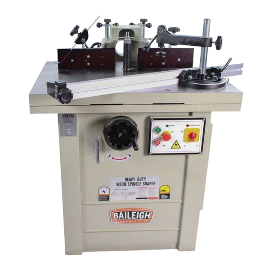
SPINDLE SHAPER
MODEL: SS-3528-S
Baileigh Industrial, Inc.
P.O. Box 531
Manitowoc, WI 54221-0531
Phone: 920.684.4990
Fax: 920.684.3944
sales@baileigh.com
REPRODUCTION OF THIS MANUAL IN ANY FORM WITHOUT WRITTEN APPROVAL OF BAILEIGH INDUSTRIAL, INC.
IS PROHIBITED. Baileigh Industrial, Inc. does not assume and hereby disclaims any liability for any damage or loss
caused by an omission or error in this Operator's Manual, resulting from accident, negligence, or other occurrence.
Rev. 03/2017
© 2017 Baileigh Industrial, Inc.
Advertisement
Table of Contents

Related Manuals for Baileigh SS-3528-S


Summary of Contents for Baileigh SS-3528-S
- Page 1 REPRODUCTION OF THIS MANUAL IN ANY FORM WITHOUT WRITTEN APPROVAL OF BAILEIGH INDUSTRIAL, INC. IS PROHIBITED. Baileigh Industrial, Inc. does not assume and hereby disclaims any liability for any damage or loss caused by an omission or error in this Operator’s Manual, resulting from accident, negligence, or other occurrence.
-
Page 2: Table Of Contents
Table of Contents THANK YOU & WARRANTY ..................1 INTRODUCTION ......................3 GENERAL NOTES ......................3 SAFETY INSTRUCTIONS ....................4 SAFETY PRECAUTIONS ....................8 Dear Valued Customer: ....................8 SAFETY: SPECIFIC RULES ..................11 TECHNICAL SPECIFICATIONS ................... 13 TECHNICAL SUPPORT ....................13 UNPACKING AND CHECKING CONTENTS .............. - Page 3 EXPLODED VIEM: STAND ASSEMBLY ..............36 Parts List: Stand Assembl y ..................37 EXPLODED VIEW: SPINDLE ..................38 Parts List: Spindle ...................... 39 EXPLODED: MOTOR AND SPINDLE BASE .............. 40 Parts List: Motor and Spindle Base ................41 EXPLODED: HOOD ASSEMBLY .................. 43 Parts List: Hood Assembly ..................
-
Page 4: Thank You & Warranty
THANK YOU & WARRANTY Thank you for your purchase of a machine from Baileigh Industrial. We hope that you find it productive and useful to you for a long time to come. Inspection & Acceptance. Buyer shall inspect all Goods within ten (10) days after receipt thereof. Buyer’s payment shall constitute final acceptance of the Goods and shall act as a waiver of the Buyer’s rights to inspect or... - Page 5 Baileigh Industrial makes every effort to ensure that our posted specifications, images, pricing and product availability are as correct and timely as possible. We apologize for any discrepancies that may occur. Baileigh Industrial reserves the right to make any and all changes deemed necessary in the course of business including but not limited to pricing, product specifications, quantities, and product availability.
-
Page 6: Introduction
After receiving your equipment remove the protective container. Do a complete visual inspection, and if damage is noted, photograph it for insurance claims and contact your carrier at once, requesting inspection. Also contact Baileigh Industrial and inform them of the unexpected occurrence. Temporarily suspend installation. -
Page 7: Safety Instructions
IMPORTANT PLEASE READ THIS OPERATORS MANUAL CAREFULLY It contains important safety information, instructions, and necessary operating procedures. The continual observance of these procedures will help increase your production and extend the life of the equipment. SAFETY INSTRUCTIONS LEARN TO RECOGNIZE SAFETY INFORMATION This is the safety alert symbol. - Page 8 SAVE THESE INSTRUCTIONS. Refer to them often and use them to instruct others. PROTECT EYES Wear safety glasses or suitable eye protection when working on or around machinery. PROTECT AGAINST NOISE Prolonged exposure to loud noise can cause impairment or loss of hearing.
- Page 9 ENTANGLEMENT HAZARD – ROTATING SPINDLE Contain long hair, DO NOT wear jewelry or loose fitting clothing. ROTATING SPINDLE ABRASIONS DO NOT place hands or fingers near, or in contact with sanding spindle during operation. HIGH VOLTAGE USE CAUTION IN HIGH VOLTAGE AREAS. DO NOT assume the power to be off.
- Page 10 Wear Eye Protection Read Manual Wear Ear Protection Wear Respiratory Protection Disconnect Power Electric Shock...
-
Page 11: Safety Precautions
All Baileigh woodworking machines should be used only for their intended use. Baileigh does not recommend or endorse making any modifications or alterations to a Baileigh machine. Modifications or alterations to a machine may pose a substantial risk of injury to the operator or others and may do substantial damage to the machine. - Page 12 7. Feeding the Piece Part. ALWAYS feed the piece part against the rotation of the cutter. NEVER force materials through the shaper. Excessive force against the shaper cutter will cause dangerous kickback conditions and can result in poor cuts. 8. Hand Positioning. NEVER place hands directly over or in front of the shaper cutter. ALWAYS keep hand at least 6”...
- Page 13 24. Keep children away. Children must never be allowed in the work area. DO NOT let them handle machines, tools, or extension cords. 25. DO NOT operate machine if under the influence of alcohol or drugs. Read warning labels on prescriptions. If there is any doubt, DO NOT operate the machine. 26.
-
Page 14: Safety: Specific Rules
SAFETY: SPECIFIC RULES READ THE MANUAL. Know the limitations and hazards in using the shaper. One SAFETY rule decal and one DANGER decal are placed on each machine as reminders of good safety practice. SHORT STOCK. Never shape stock less than 12 inches in length without special fixtures. Where practical, shape longer stock and cut to size. - Page 15 SPINDLE SPEED. Do not operate tools at speeds higher than rated by the manufacturer. CUTTER SELECTION. Use only those cutters designed to be used on the machine, and mount only safety type cutters on the spindle. STOCK CONDITION. The danger of kicked back stock can occur when the stock has knots, holes, or foreign objects such as nails.
-
Page 16: Technical Specifications
(other than die sets and blades). For specific application needs or future machine purchases contact the Sales Department at: sales@baileigh.com, Phone: 920.684.4990, or Fax: 920.684.3944. Note: The photos and illustrations used in this manual are representative only and may not depict the actual color, labeling or accessories and may be intended to illustrate technique only. -
Page 17: Unpacking And Checking Contents
UNPACKING AND CHECKING CONTENTS Your Baileigh machine is shipped complete. Separate all parts from the packing material and check each item carefully. Make certain all items are accounted for before discarding any packing material. WARNING: SUFFOCATION HAZARD! Immediately discard any plastic bags and packing materials to eliminate choking and suffocation hazards to children and animals. -
Page 18: Transporting And Lifting
TRANSPORTING AND LIFTING IMPORTANT: Lifting and carrying operations should be carried out by skilled workers, such as a truck operator, crane operator, etc. If a crane is used to lift the machine, attach the lifting chain carefully, making sure the machine is well balanced. Guidelines when lifting with truck or trolley: ... -
Page 19: Installation
INSTALLATION IMPORTANT: Consider the following when looking for a suitable location to place the machine: Overall weight of the machine. Weight of material being processed. Sizes of material to be processed through the machine. Space needed for auxiliary stands, work tables, or other machinery. ... -
Page 20: Electrical
ELECTRICAL CAUTION: HAVE ELECTRICAL UTILITIES CONNECTED TO MACHINE BY A CERTIFIED ELECTRICIAN! Check if the available power supply is the same as listed on the machine nameplate. WARNING: Make sure the grounding wire (green) is properly connected to avoid electric shock. DO NOT switch the position of the green grounding wire if any electrical plug wires are switched during hookup. -
Page 21: Power Cord Connection
Improper connection of the equipment-grounding conductor can result in risk of electric shock. The conductor with insulation having an outer surface that is green with or without yellow stripes is the equipment-grounding conductor. If repair or replacement of the electric cord or plug is necessary, do not connect the equipment-grounding conductor to a live terminal. -
Page 22: Adjustments
ADJUSTMENTS Check all mounting screws and bolts to see that they are tight. CAUTION: When changing tools, adjusting the drive belt, or doing cleanup and maintenance, always turn the machine off and unplug the machine from its power source. SQUARING THE FENCE Periodically the wood fence will have to be squared with the mounting surface and adjusted parallel to each other. -
Page 23: Changing Spindle
CHANGING SPINDLE The shaper is supplied with both 3/4” and 1’ and 1 1/4” spindle assemblies. These assemblies are locked in a tapered seat with a draw bar and nut. To change spindles, place one wrench on the flats on the top of the spindle and another wrench on the draw bar nut underneath the spindle drive sheave as shown in Figure 8. -
Page 24: Before Operating
BEFORE OPERATING Turn the motor on momentarily to check for proper rotation. The spindle should rotate counterclockwise when looking down on the spindle. Correct as required. Run the machine for a short period of time to insure that the moving parts are working properly with no excessive vibration. -
Page 25: Grain Direction
GRAIN DIRECTION Plan to shape the work piece in the same direction as the grain when possible. Some open grain woods (such as redwood, fir, and oak) will leave a rough, or slightly splintered edge when cut against the grain. DANGER: Deep cuts require excessive horsepower and pushing force to control the cut. -
Page 26: Edge Shaping: Long Boards
3. Reconnect power to the machine. 4. Take a trial cut on a piece of scrap of the same thickness as work piece. Note: Only a short cut is necessary to determine if the profile, depth, and height of cut is correct. 5. -
Page 27: End Shaping
END SHAPING WARNING: End shaping a narrow workpiece without a special guide could result in the workpiece rocking into the cutterhead causing minor, or major, personal injury. When end shaping narrow stock, it is important that at least one half of the workpiece end be in contact with either the infeed or outfeed fence as shown in Figure 15. -
Page 28: Straightline Bevel Edge Shaping
STRAIGHTLINE BEVEL EDGE SHAPING To perform a bevel edge cut, the infeed edge of the jig is placed against the infeed fence and clamped to the table, as shown in Figure 18. The outfeed fence is moved forward as necessary to compensate for the cut. - Page 29 Note: Since the collar requires at least 1/8" of surface edge to ride against, the entire edge cannot be shaped as shown in Figure 21. The use of a pattern, however, permits the shaping of the entire contour edge. If the workpiece is to be shaped all around the perimeter, hold it firmly and push the work straight into the cutter until the depth of cut is established by the collar as shown in Figure 22.
- Page 30 Large circular and arc-shaped stock can be shaped as described under “CONTOUR EDGE SHAPING”; however, small sized stock requires the use of special shaping jigs similar to those shown in Figure 24 and 25. With the entire fence assembly removed, carefully position the jig for desired depth of cut and securely clamp to the table.
-
Page 31: Enclosed Edge Shaping
ENCLOSED EDGE SHAPING WARNING: Enclosed edge shaping is extremely dangerous. The operator must be aware at all times of the direction of feed. WARNING: Unless the workpiece is attached to a larger wooden base, NEVER perform enclosed edge shaping if there is less than 12” of workpiece material all around the opening. -
Page 32: Templates
TEMPLATES The template, which is usually made of 3/4” scrap material, must be thick enough to provide a solid bearing edge against a collar. When constructing a template similar to the one shown in Figure 28, keep in mind that it serves only as a guide for the cutter. -
Page 33: Horizontal Toggle Clamp
In many situations the workpiece is positioned against the template using dowels as anchor points and handles (wood blocks) to assist the operator in guiding the workpiece through the cut as shown in Figure 31. HORIZONTAL TOGGLE CLAMP The horizontal toggle clamp, similar to those illustrated in Figure 32, is especially useful when ordinary “C”... -
Page 34: Sash And Door Shaping
SASH AND DOOR SHAPING Shaping a door still requires two operations. Figure 33 shows the sash cut for the first operation. Figure 34 shows the stock flipped over and the sash cutter used with a 1/4" groove cutter to complete the cut. Figure 35 shows the first shaping cut with the sash cutter for the matching door stile sash. -
Page 35: Butt Joints
Figure 37 shows the first shaping out for a window-sash stile utilizing a sash cutter, collar, collar, and a 1/2" groove cutter. Figure 38 shows both cuts required for a window-sash rail end. The first operation at top is a rabbet cut made with a groove cutter. -
Page 36: Taper Cuts
TAPER CUTS OFFSETTING THE FENCES CAUTION: Do not use the standard fence for short work (12 inches or less in length on the side to be cut). Instead, use a miter gauge or special fixture to avoid losing control of the workpiece. Taper cuts can be made by offsetting the fences for the amount of taper desired, or with a layout line on the stock which can be made parallel to the infeed fence as shown in... -
Page 37: Tenoning
TENONING The tenoning fixture illustrated in Figure 43 shows a miter gauge equipped with a hold down for shaping the ends of narrow workpieces. The miter gauge can also be adapted to cut square and centered tenons at the ends of legs for tables, chairs, etc. -
Page 38: Troubleshooting
TROUBLESHOOTING WARNING: Make sure the electrical disconnect is OFF before working on the machine. Trouble Possible cause Solution 1. Shaper not plugged in 1. Plug in shaper 2. Fuse blown or circuit breaker 2. Replace fuse or reset circuit Shaper will not start tripped breaker 3. -
Page 39: Exploded Viem: Stand Assembly
EXPLODED VIEM: STAND ASSEMBLY... -
Page 40: Parts List: Stand Assembly
Parts List: Stand Assembly Item Description Set Screw Cup Pt. 5/16" x 5/8" Table Table Insert (Big) Table Insert (Mid) Table Insert (Little) Stand Assembly Hex Nut 3/8” Lock Washer 3/8” Washer 3/8” - Ø 20 Table Brace (R) Hex Nut 3/16” Screw Rd Hd 1/4”... -
Page 41: Exploded View: Spindle
EXPLODED VIEW: SPINDLE... -
Page 42: Parts List: Spindle
Parts List: Spindle Item Description Bolt Lock Nut Lock Bearing 6008ZZ Snap Ring C-40 Pulley Spindle Washer Lock Nut Lock Spindle 1-1/4” Shaft V2.0 Key 7mm Quill V2.0 Nut 3/4” Nut 1” Collar 1-1/4” x 1/4” - 1pcs Collar 1-1/4” x 3/8” - 1pcs Collar 1-1/4”... -
Page 43: Exploded: Motor And Spindle Base
EXPLODED: MOTOR AND SPINDLE BASE... -
Page 44: Parts List: Motor And Spindle Base
Parts List: Motor and Spindle Base Item Description Set Screw Cup Pt. 5/16" x 5/8" Hex Nut 3/8" Lock Washer 3/8" Washer 3/8" - Ø 20 Bolt Hex Hd. 3/8" x 1-1/4" Bolt Hex Hd 3/8" x3/4" Quill Bolt Hex Hd 1/4" x 5/8" Lock Washer 1/4"... - Page 45 Item Description Lock Washer 5/16" Socket Hd. Cap. Scr. 5/16" x 1" Spring Motor Shaft Spring Washer 1/2" - Ø 35 Base Motor Knob Lock Washer 1/2" Bolt Hex. Hd. 1/2" x 1-1/2" Pointer Screw 3/16" x 3/8" Bolt Hex. Hd. 5/16" x 3/4" Shaft Guide Plate Plate Motor...
-
Page 46: Exploded: Hood Assembly
EXPLODED: HOOD ASSEMBLY... -
Page 47: Parts List: Hood Assembly
Parts List: Hood Assembly Item Description Lock Washer 1/4” Washer 1/4’ Nut 5/16” Lock Washer 5/16” Washer 1/2” Screw 5/16” x 3/4” Screw 1/4” x 3/4” Nut 1/4” Handle Lock Bracket Screw Guide Screw Guide Shaft Guide Knob Washer 5/16” Plate Guard Set Screw 1/4”... -
Page 48: Exploded: Fence And Guide Assembly
EXPLODED: FENCE AND GUIDE ASSEMBLY... -
Page 49: Parts List: Fence And Guide Assembly
Parts List: Fence and Guide Assembly Item Description Table Eccentric Pulley Shaft C-Ring R35 Bearing 6202Z Pulley Spring Washer 5/16" Screw 5/16" x 1-1/2" Cap Screw 1/2" x 1-1/2" Nut 1/2" C-Ring C8 Shaft Spring C-Ring C15 Press Wheel Press Shaft Plastic Nut Press Wood Base Handle Lock... - Page 50 Item Description Screw 3/16" x 1/4" Glide Table C-Ring C-10 Bearing 6900ZZ Eccentric Pulley Shaft Cap Screw 1/4" x 1-1/4' Bearing Base Resist Base Table Fix Shaft Spring Table Fix Spring Shaft Pin 3 x 16mm Cap Screw 1/4" x 1-1/2' Spacer Guide Orbit 3/8 Knob...
-
Page 51: Electrical Schematic
ELECTRICAL SCHEMATIC... - Page 52 , WI 54220 UFEK RIVE ANITOWOC : 920. 684. 4990 F : 920. 684. 3944 HONE BAILEIGH BAILEIGH INDUSTRIAL, INC. 1455 S. C , CA 91761 AMPUS VENUE NTARIO : 920. 684. 4990 F : 920. 684. 3944 HONE BAILEIGH INDUSTRIAL LTD. U...
Need help?
Do you have a question about the SS-3528-S and is the answer not in the manual?
Questions and answers