Table of Contents
Advertisement
Quick Links
OPERATOR'S MANUAL
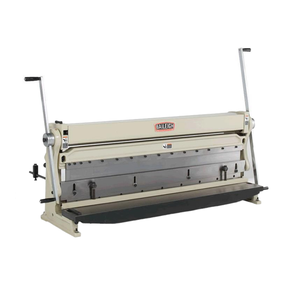
3-IN-1 COMBINATION SHEAR, BRAKE, ROLL
MODEL: SBR-5220
Baileigh Industrial, Inc.
P.O. Box 531
Manitowoc, WI 54221-0531
Phone: 920.684.4990
Fax: 920.684.3944
sales@baileigh.com
REPRODUCTION OF THIS MANUAL IN ANY FORM WITHOUT WRITTEN APPROVAL OF BAILEIGH INDUSTRIAL, INC.
IS PROHIBITED. Baileigh Industrial, Inc. does not assume and hereby disclaims any liability for any damage or loss
caused by an omission or error in this Operator's Manual, resulting from accident, negligence, or other occurrence.
Rev. 05/2016
© 2016 Baileigh Industrial, Inc.
Advertisement
Table of Contents

Subscribe to Our Youtube Channel
Related Manuals for Baileigh SBR-5220


Summary of Contents for Baileigh SBR-5220
- Page 1 REPRODUCTION OF THIS MANUAL IN ANY FORM WITHOUT WRITTEN APPROVAL OF BAILEIGH INDUSTRIAL, INC. IS PROHIBITED. Baileigh Industrial, Inc. does not assume and hereby disclaims any liability for any damage or loss caused by an omission or error in this Operator’s Manual, resulting from accident, negligence, or other occurrence.
-
Page 2: Table Of Contents
Table of Contents THANK YOU & WARRANTY ..................1 INTRODUCTION ......................3 GENERAL NOTES ......................3 SAFETY INSTRUCTIONS ....................4 SAFETY PRECAUTIONS ....................7 Dear Valued Customer: ....................7 TECHNICAL SPECIFICATIONS ................... 10 TECHNICAL SUPPORT ....................10 UNPACKING AND CHECKING CONTENTS ..............11 Cleaning ........................ - Page 3 Replace Blades ......................37 PARTS IDENTIFICATION DRAWING - A ..............38 PARTS IDENTIFICATION DRAWING - B ..............39 PARTS IDENTIFICATION DRAWING - C ..............40 Parts List ........................41 TROUBLESHOOTING ....................43 Shear Operation ......................43 Brake Operation ......................43 Slip Roll Operation .....................
-
Page 4: Thank You & Warranty
THANK YOU & WARRANTY Thank you for your purchase of a machine from Baileigh Industrial. We hope that you find it productive and useful to you for a long time to come. Inspection & Acceptance. Buyer shall inspect all Goods within ten (10) days after receipt thereof. Buyer’s payment shall constitute final acceptance of the Goods and shall act as a waiver of the Buyer’s rights to inspect or... - Page 5 Baileigh Industrial makes every effort to ensure that our posted specifications, images, pricing and product availability are as correct and timely as possible. We apologize for any discrepancies that may occur. Baileigh Industrial reserves the right to make any and all changes deemed necessary in the course of business including but not limited to pricing, product specifications, quantities, and product availability.
-
Page 6: Introduction
After receiving your equipment remove the protective container. Do a complete visual inspection, and if damage is noted, photograph it for insurance claims and contact your carrier at once, requesting inspection. Also contact Baileigh Industrial and inform them of the unexpected occurrence. Temporarily suspend installation. -
Page 7: Safety Instructions
IMPORTANT PLEASE READ THIS OPERATORS MANUAL CAREFULLY It contains important safety information, instructions, and necessary operating procedures. The continual observance of these procedures will help increase your production and extend the life of the equipment. SAFETY INSTRUCTIONS LEARN TO RECOGNIZE SAFETY INFORMATION This is the safety alert symbol. - Page 8 SAVE THESE INSTRUCTIONS. Refer to them often and use them to instruct others. PROTECT EYES Wear safety glasses or suitable eye protection when working on or around machinery. PROTECT AGAINST NOISE Prolonged exposure to loud noise can cause impairment or loss of hearing.
- Page 9 KEEP CLEAR OF MOVING OBJECTS Always be aware of the position of the clamp handle and the counterweight. They are heavy and can swing back suddenly causing serious body or head injuries. BEWARE OF PINCH POINTS Keep hands and fingers away from the rolls when the machine is in operation.
-
Page 10: Safety Precautions
Baileigh does not recommend or endorse making any modifications or alterations to a Baileigh machine. Modifications or alterations to a machine may pose a substantial risk of injury to the operator or others and may do substantial damage to the machine. - Page 11 8. Do not force tool. Your machine will do a better and safer job if used as intended. DO NOT use inappropriate attachments in an attempt to exceed the machines rated capacity. 9. Use the right tool for the job. DO NOT attempt to force a small tool or attachment to do the work of a large industrial tool.
- Page 12 30. Keep visitors a safe distance from the work area. WARNING: Before operating the Baileigh Shear, Brake, Roll make sure it is firmly bolted to a table, bench, or the floor. If it tips over on you, it could cause severe injury or death.
-
Page 13: Technical Specifications
(other than die sets and blades). For specific application needs or future machine purchases contact the Sales Department at: sales@baileigh.com, Phone: 920.684.4990, or Fax: 920.684.3944. Note: The photos and illustrations used in this manual are representative only and may not depict the actual color, labeling or accessories and may be intended to illustrate technique only. -
Page 14: Unpacking And Checking Contents
UNPACKING AND CHECKING CONTENTS Your Baileigh machine is shipped complete. Separate all parts from the packing material and check each item carefully. Make certain all items are accounted for before discarding any packing material. WARNING: SUFFOCATION HAZARD! Immediately discard any plastic bags and packing materials to eliminate choking and suffocation hazards to children and animals. - Page 15 Combination Shear, Brake, Roll Rear Stop Handlebars Rear Stop Rods Covers...
-
Page 16: Transporting And Lifting
TRANSPORTING AND LIFTING IMPORTANT: Lifting and carrying operations should be carried out by skilled workers, such as a truck operator, crane operator, etc. If a crane is used to lift the machine, attach the lifting chain carefully, making sure the machine is well balanced. Follow these guidelines when lifting with truck or trolley: ... -
Page 17: Installation
INSTALLATION WARNING: It is absolutely imperative that this machine be anchored securely to the floor to prevent tipping. If this machine is installed on a work bench or stand of any type, then the mounting to the bench or stand AND the stand must be anchored in such a way as to prevent tipping. -
Page 18: Anchoring The Machine
4” (102mm) thick. 6” (153mm) minimum is preferred. .50" (12.7mm) If you intend to mount the Baileigh machine on a workbench be aware of the following: Overall weight of the machine. Weight of material being processed. -
Page 19: Overall Dimensions
OVERALL DIMENSIONS 71.50" 54.50" .44"Ø 56.25" Mounting Holes... -
Page 20: Getting To Know Your Machine
GETTING TO KNOW YOUR MACHINE Item Description Function Back Gauge Controls material stop distance for brake and shear Rear Roller Adjustment Knob Clockwise to raise and counterclockwise to lower Handlebar Adjustment Knob Loosen knob and adjust handlebar position Handlebars Controls motion of the rolls, shear, and brake Upper Roller Adjustment Knob Clockwise to lower and counterclockwise to raise Slip Roll Cover Covers rolls when not being used... -
Page 21: Assembly And Set Up
ASSEMBLY AND SET UP 1. This machine comes with one long (39.5” [1003mm]) and one short (31.5” [800mm]) handlebars. It is the owners/operators choice as to which end of the machine the handlebars are installed into. 2. Remove the swivel handle (52) from the handlebar. 3. -
Page 22: Shear Overview
SHEAR OVERVIEW The shear section has blades that can be reversed to provide a sharp edge as needed and are capable of shearing up to 20 gauge (0.912mm) mild steel sheet x 52” (1321mm) wide. An adjustable upper blade assembly passes by a fixed lower blade resulting in a precise shearing action. -
Page 23: Shearing Sheet Metal
SHEARING SHEET METAL WARNING: Before operating the Baileigh Shear, Brake, Roll make sure it is firmly bolted to a table, bench, or the floor. If it tips over on you, it could cause severe injury or death. WARNING : The shearing blades pose an amputation hazard. Make sure no body part or clothing is near the specific hazard. - Page 24 6. In a coordinated fashion, both operators should rotate the handlebar to begin the cut. The shearing action begins at the left side of the piece part and continues to the right until the cut is complete. a. The pressure plate (#63) should make contact with the sheet before the blade (#46) does.
-
Page 25: Shear Blade Adjustments
SHEAR BLADE ADJUSTMENTS To obtain optimum results, shear alignment and shear bow are two conditions which may need to be adjusted depending on the gauge and type of material you want to shear. Shears that are out of adjustment may lead to uneven or ragged cuts. -
Page 26: Hold Down Adjustment
HOLD DOWN ADJUSTMENT When the shearing cycle starts, the spring loaded hold down pushes on the piece part to secure it. It also helps keep the operator’s fingers away from the cutting blades. When adjusted properly there should be no more than 1/4” (6.3mm) of clearance below the hold down to feed the piece part. -
Page 27: Removal Of Brake Blades For Cleaning And Setup
REMOVAL OF BRAKE BLADES FOR CLEANING AND SETUP Turn the handlebar counterclockwise (ccw) to raise the brake blade die until it contacts the brake blades as shown at right. Using a hex wrench, loosen all of the capscrews holding the gib. Now slide the brake blades out, one at a time. -
Page 28: Brake Overview
BRAKE OVERVIEW The Combination SBR has adjustable and removable fingers to offer a wide variety of bending brake options. The brake section is capable of bending up to 20ga. (0.912mm) x 52” (1321mm) wide mild steel sheet. To start a bend, the operator places a piece of sheet metal on the blade brake die. By turning the handlebar, the brake die is raised up until the tips of the brake blades line up with a line scribed on the sheet metal. -
Page 29: Bending Sheet Metal
WARNING: Before operating the Baileigh Shear, Brake, Roll make sure it is firmly bolted to a table, bench, or the floor. If it tips over on you, it could cause severe injury or death. - Page 30 8. While the sheet metal is being held firmly, both operators should rotate the handlebar to make the bend to the desired angle. 9. Raise the brake blade die and remove the piece part. Note: The brake die is designed to bend material up to 90°. Adjust the fingers for box and pan bending: 1.
-
Page 31: Slip Roll Overview
SLIP ROLL OVERVIEW The slip roll section can be used to roll up to 20ga. (0.912mm) x 52” (1321mm) wide mild steel. It consists of 3 hardened rolls. The rear roll is adjustable to control the radius of the piece part as it is being formed. -
Page 32: Operating The Slip Roll
OPERATING THE SLIP ROLL WARNING: Before operating the Baileigh Shear, Brake, Roll make sure it is firmly bolted to a table, bench, or the floor. If it tips over on you, it could cause severe injury or death. WARNING: Rolling poses a pinching hazard. Make sure no body part or clothing is near the specific hazard. -
Page 33: Rolling Operation
consistent gap piece part Rolling Operation 1. Back off the idler roll by turning the two adjustment bolts counterclockwise (ccw) as in view “A” below. 2. Unscrew the top roll adjustment bolts until there is enough gap between the top and bottom rolls to allow the piece part to fit between. - Page 34 8. Now that you have a pre-bend on both ends, it is time to roll the final diameter. 9. Back down the rear idler roll and start rolling the piece forward and reverse as shown in view “D”. 10. Start raising the idler roll gradually and continue rolling the piece forward and reverse until you have reached the finished diameter.
-
Page 35: Rolling Round Shapes
Rolling Round Shapes .187” .25” .312” There are three wire or forming grooves located on the right end of the upper and lower rolls. They can be used to form solid wire, rods, and small tubing. To make rings, follow the “Determining Length of Material” procedure to calculate the actual length. -
Page 36: Bending Allowance
BENDING ALLOWANCE In order to bend sheet metal accurately, you will need to consider the total length of each bend. This is referred to as bend allowance. Subtract the bend allowance from the sum of the outside dimensions of the piece part to obtain the actual overall length or width of the piece. Because of differences in sheet metal hardness, and whether the bend is made with the grain or against it, exact allowances must sometimes be made by trial and error. -
Page 37: Lubrication And Maintenance
LUBRICATION AND MAINTENANCE WARNING: Maintenance should be performed on a regular basis by qualified personnel. Always follow proper safety precautions when working on or around any machinery. Check for the following conditions and repair or replace when necessary: Check daily for any unsafe conditions and fix immediately. ... -
Page 38: Slip Roll Maintenance
SLIP ROLL MAINTENANCE Every (6) months remove and lubricate the roller bushings. 1. With the aid of an assistant carefully remove the top front roll. To do so, back off both top roll adjustment bolts, and rotate the roll release pin (left side of roll), 90°. Be careful not to damage the roll. -
Page 39: Brake Alignment
BRAKE ALIGNMENT WARNING: The bending brake poses a pinching hazard. Make sure no body part or clothing is near the specific hazard. Failure to follow this warning could result in severed or crushed fingers. On occasion, it may become necessary to realign the brake blades and the brake die. -
Page 40: Replacing The Shear Blade
When the blade edge has been ground to the point that the blade gap can no longer be set correctly, replace the blades as a set. Contact Baileigh Industrial for replacement blades. Replace Blades 9. -
Page 41: Parts Identification Drawing - A
PARTS IDENTIFICATION DRAWING - A... -
Page 42: Parts Identification Drawing - B
PARTS IDENTIFICATION DRAWING - B... -
Page 43: Parts Identification Drawing - C
PARTS IDENTIFICATION DRAWING - C... -
Page 44: Parts List
Parts List Item Description Qty. Item Description Qty. Left Side Member Blade-Upper Shear Table Hold Down Crossbeam Side Guide Crank Arm Hold Down Spring Right Side Member Hex Stud Connector Pin Seat Cover Left And Right Press Block Bushing Right Gear Cover Large Gear Long Handlebar Left Gear Cover... - Page 45 Item Description Qty. Item Description Qty. Bending Bar Hex Bolt 10 x 40mm Brake Blade (Assorted Sizes) Flt. Hd. Soc. Capscrew 8 x 25mm 16 Brake Blade Die Socket Capscrew 16 x 45mm Adjusting Plate Grease Fitting Movable Blade Mount Socket Capscrew 6 x 20mm...
-
Page 46: Troubleshooting
TROUBLESHOOTING Shear Operation FAULT PROBABLE CAUSE REMEDY Widen gap for thicker material Can’t shear material Improper blade gap distance, exceeding machine capacities Adjust blade gap to be equal Cuts are not square. Blade unequal across across length, Adjust blade bow, length, Too much bow in blade, Adjust hold down gap. - Page 47 NOTES...
- Page 48 , WI 54220 UFEK RIVE ANITOWOC : 920. 684. 4990 F : 920. 684. 3944 HONE www.baileigh.com BAILEIGH INDUSTRIAL, INC. 1455 S. C , CA 91761 AMPUS VENUE NTARIO : 920. 684. 4990 F : 920. 684. 3944 HONE BAILEIGH INDUSTRIAL LTD. U...
Need help?
Do you have a question about the SBR-5220 and is the answer not in the manual?
Questions and answers