Table of Contents
Advertisement
Quick Links
OPERATOR'S MANUAL
REPRODUCTION OF THIS MANUAL IN ANY FORM WITHOUT WRITTEN APPROVAL OF BAILEIGH INDUSTRIAL, INC.
IS PROHIBITED. Baileigh Industrial, Inc. does not assume and hereby disclaims any liability for any damage or loss
caused by an omission or error in this Operator's Manual, resulting from accident, negligence, or other occurence.
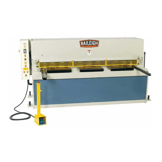
HYDRAULIC SHEAR
MODEL: SH-8008HD
Baileigh Industrial, Inc.
P.O. Box 531
Manitowoc, WI 54221-0531
Phone: 920.684.4990
Fax: 920.684.3944
sales@baileighindustrial.com
© 2012 Baileigh Industrial, Inc.
Rev. 4/2012
Advertisement
Table of Contents

Subscribe to Our Youtube Channel
Related Manuals for Baileigh SH-8008HD


Summary of Contents for Baileigh SH-8008HD
- Page 1 REPRODUCTION OF THIS MANUAL IN ANY FORM WITHOUT WRITTEN APPROVAL OF BAILEIGH INDUSTRIAL, INC. IS PROHIBITED. Baileigh Industrial, Inc. does not assume and hereby disclaims any liability for any damage or loss caused by an omission or error in this Operator’s Manual, resulting from accident, negligence, or other occurence.
-
Page 2: Table Of Contents
Table of Contents THANK YOU & WARRANTY ....................1 INTRODUCTION ......................3 GENERAL NOTES ......................3 SAFETY INSTRUCTIONS ....................4 SAFETY PRECAUTIONS ....................6 Emergency Stop Button ....................7 Electrical Enclosure Disconnect Switch ............... 8 Hazard Signs ....................... 8 TECHNICAL SPECIFICATIONS ..................9 MACHINE FEATURES .................... - Page 3 MANIFOLD BLOCK ...................... 39 HYDRAULIC COMPONENT IDENTIFICATION ............40 HYDRAULIC CYLINDER PARTS IDENTIFICATION ............ 42 HOLD DOWN CYLINDER PARTS IDENTIFICATION ..........43 ELECTRICAL ENCLOSURE BACK PANEL ..............44 ELECTRICAL COMPONENT IDENTIFICATION ............45 ELECTRICAL PARTS LIST ..................46 Additional Electrical Components ................46 ELECTRICAL SCHEMATIC (Sheet.
-
Page 4: Thank You & Warranty
THANK YOU & WARRANTY Thank you for your purchase of a machine from Baileigh Industrial. We hope that you find it productive and useful to you for a long time to come. Inspection & Acceptance. Buyer shall inspect all Goods within ten (10) days after receipt thereof. Buyer’s payment shall constitute final acceptance of the Goods and shall act as a waiver of the Buyer’s rights to inspect... - Page 5 Baileigh Industrial makes every effort to ensure that our posted specifications, images, pricing and product availability are as correct and timely as possible. We apologize for any discrepancies that may occur. Baileigh Industrial reserves the right to make any and all changes deemed necessary in the course of business including but not limited to pricing, product specifications, quantities, and product availability.
-
Page 6: Introduction
After receiving your equipment remove the protective container. Do a complete visual inspection, and if damage is noted, photograph it for insurance claims and contact your carrier at once, requesting inspection. Also contact Baileigh Industrial and inform them of the unexpected occurrence. Temporarily suspend installation. -
Page 7: Safety Instructions
IMPORTANT PLEASE READ THIS OPERATORS MANUAL CAREFULLY It contains important safety information, instructions, and necessary operating procedures. The continual observance of these procedures will help increase your production and extend the life of the equipment. SAFETY INSTRUCTIONS LEARN TO RECOGNIZE SAFETY INFORMATION This is the safety alert symbol. - Page 8 PROTECT EYES Wear safety glasses or suitable eye protection when working on or around machinery. BEWARE OF SHEAR HAZARD Blade is sharp. Placing hands or fingers near blade will result in cuts and possibly loss of fingers or limbs if placed in machine. NEVER place your hand or any part of your body in this machine.
-
Page 9: Safety Precautions
SAFETY PRECAUTIONS 1. Only trained and qualified personnel can operate this machine. 2. Make sure guards are in place and in proper working order before operating machinery. 3. Remove any adjusting tools. Before operating the machine, make sure any adjusting tools have been removed. -
Page 10: Emergency Stop Button
SAFETY PRECAUTIONS (cont.) 16. Blade adjustments and maintenance. Always keep blades sharp and properly adjusted for optimum performance. 17. Keep visitors and children away. Visitors and children must never be allowed in the work area. DO NOT let them handle machines, tools, or extension cords. 18. -
Page 11: Electrical Enclosure Disconnect Switch
Electrical Enclosure Disconnect Switch The main disconnect switch (P) turns power on to the HAUPTSCHALTER MAIN SWITCH OFFNEN IN OPEN IN machine when in the “ON” position. If the door handle is 0-STELLUNG OFF - POSITION turned while the switch is “ON”, a safety catch will prevent the door from opening. -
Page 12: Technical Specifications
TECHNICAL SPECIFICATIONS 80” (2032mm) Maximum Shear Length 8 ga. (4.18mm) mild steel* Maximum Material Thickness 12 ga. (2.66mm) stainless steel** 24 – 36 Strokes/Minute 39.37” (1000mm) Front Gate Length 23.62” (600mm) Back Gate Length Blade Angle 1/2° - 2° Blade Clearance Manual Adjustment Lever Motor 15Hp (11.2Kw) -
Page 13: Transporting And Lifting
TRANSPORTING AND LIFTING 7260 lbs (3300 kg) CAUTION: Lifting and carrying operations should be carried out by skilled workers, such as a truck operator, crane operator, etc. If a crane is used to lift the machine, attach the lifting chain carefully, making sure the machine is well balanced. -
Page 14: Unpacking And Checking Contents
UNPACKING AND CHECKING CONTENTS Your Baileigh SH-8008HD Hydraulic Shear is shipped complete in one crate. Separate all parts from the packing material and check each item carefully. Make certain all items are accounted for before discarding any packing material. WARNING:... - Page 15 Back Gauge Washers and bolts Manual Back Gauge Squaring Arm with Scale and Material Stop Dog Front Supports with Material Stop Dog Pedestal with Foot Pedal and Emergency Stop Switch figure 4...
-
Page 16: Overall Dimensions
OVERALL DIMENSIONS 113.00" (2,870mm) TIMER STPY-M3 INCH AUTO LAMP MILD STEEL T.S 64000psi 20GA 10 GA 3/16" 28GA 14 GA 10GA STAINLESS T.S 100000psi 103.00" 2.00" (2,616mm) (50.8mm) 107.00" (2,718mm) 81.75" (2,076mm) 25.00" (635mm) 7.75" (196.8mm) 23.75" 3.75" (95.25mm) (603mm) 37.38"... -
Page 17: Installation
INSTALLATION Levelling The machine should be sited on a level, concrete floor. Provisions for securing it should be in position prior to placing the machine. The accuracy of any machine depends on the precise placement of it to the mounting surface. Level the table to within .003”/ft. -
Page 18: Electrical
Electrical WARNING: Baileigh Industrial is not responsible for any damage caused by wiring up to an alternative 3-phase power source other than direct 3- phase. If you are using an alternate power source, consult a certified electrician or contact Baileigh Industrial prior to energizing the machine. -
Page 19: Getting To Know Your Machine
GETTING TO KNOW YOUR MACHINE... - Page 20 Note: Shown with guard removed. (For identification purposes only!) Note: Lamp fixture shown removed from machine and flipped over.
- Page 21 Note: Shown with material drop-off shields and back gauge removed. Note: Your machine may appear slightly different from the above photos.
- Page 22 Item Description Function Blade Gap Adjusting Handle Adjusts gap according to material thickness Fluorescent Light Green light projects shadow line on material Bearing Block (Front) Consult Factory Before Adjusting Material Support Arm Supports larger sheets of material Table with Ball Transfer Allows for easy movement of material Hydraulic Hold Down Cylinders Grip the material before shearing...
-
Page 23: Electrical Enclosure Switch And Button Functions
Electrical Enclosure Switch and Button Functions WARNING: Before opening the door to work on electrical circuits, turn the main disconnect switch “OFF”. Also turn off and Lock Out the electrical supply source to this machine. FAILURE TO FOLLOW THESE INSTRUCTIONS MAY RESULT IN FATAL OR SERIOUS INJURY. - Page 24 WORKPIECE COUNTER – The counter registers each completed cycle that the upper blade makes. The slide switch at the upper right of the counter, when in the locked position, keeps the counter from accidentally being reset. To reset the counter, press the button in the upper left corner.
- Page 25 CUTTING MODE SELECTOR SWITCH – This is a 3- position selector switch which allows you to pick one INCH of three shearing modes. Pressing the foot pedal in AUTO the SIN (singular) mode will complete one full shear cycle. In INCH mode the top blade can be stepped down gradually.
-
Page 26: Blade Gap Adjusting Handle
Blade Gap Adjusting Handle The process of shearing can produce a shear edge burr. This burr can be minimized by adjusting the blade gap to the thickness of material being sheared and by keeping the blades sharp. The gap distance (fig.12) is changed by positioning the handle up or down as in (fig. -
Page 27: Manual Back Gauge
Manual Back Gauge The back gauge is used to adjust the setting of the back gauge dimension to control the size of the pieces dropping behind the blades. The manual back gauge assembly will need to be attached to the back end of the shear. There are two blocks with holes in them for this purpose. -
Page 28: Squaring Arm
Squaring Arm The squaring arm is used to square the material to the shear blade. It can also be used for front gauging by utilizing the graduated scale or as a material support. The adjustable rotating dog pivots out of the way when material passes over it. The dog pops up when the material passes allowing it to be used as a stop at a predetermined dimension. -
Page 29: Connecting Cable To Pedestal
Rake Angle The Baileigh SH-8008HD shear has a variable rake angle that can be adjusted to suit the width of the piece part that is being cut. Rake angle is the angle of the moving blade as it passes the fixed blade and is a factor in determining a quality cut. -
Page 30: Shear Operating Procedure
SHEAR OPERATING PROCEDURE Start Machine Power 1. Turn the main disconnect clockwise to the ON position (A). 2. The POWER lamp (B) will be illuminated. Start Hydraulic Pump Motor 1. Verify that the inlet and outlet valves on the hydraulic tank are open. -
Page 31: Single Mode
Single Mode CAUTION: Always wear proper eye protection with side shields, safety footwear, and leather gloves to protect from burrs and sharp edges. Keep hands and fingers clear of the shearing blade and clamping cylinders. When handling large heavy sheets make sure they are properly supported. When performing a cut in the SIN mode, pressing the foot pedal will complete one full shear cycle. -
Page 32: Auto Mode
Auto Mode CAUTION: Always wear proper eye protection with side shields, safety footwear, and leather gloves to protect from burrs and sharp edges. Keep hands and fingers clear of the shearing blade and clamping cylinders. When handling large heavy sheets make sure they are properly supported. When performing a cut in AUTO mode, pressing and holding the foot pedal will cycle the upper blade continuously as long as the foot pedal is depressed. -
Page 33: Inch Mode
Inch Mode CAUTION: Always wear proper eye protection with side shields, safety footwear, and leather gloves to protect from burrs and sharp edges. Keep hands and fingers clear of the shearing blade and clamping cylinders. When handling large heavy sheets make sure they are properly supported. When in the INCH mode the upper blade can be stepped down gradually. -
Page 34: Rake Angle Adjustment (Increase)
Rake Angle Adjustment (Increase) PUSH THIS BUTTON REPEATEDLY TO PUMP MOTOR TURN THIS INCREASE THE IS "ON" SWITCH "ON" RAKE ANGLE MILD STEEL T.S 64000psi 14GA 3/16" 1/4" 10 GA 18GA 3/16" STAINLESS T.S 100000psi RAKE ANGLE INDICATOR LED WILL BE "ON" WHEN IT IS IN THAT POSITION. WHEN REACHING MAXIMUM ANGLE (1/4"... -
Page 35: Turning Off Machine Power
Turning Off Machine Power INCH LAMP AUTO TURN CUTTING MODE SELECTOR TURN THIS TURN THIS SWITCH TO "INCH" SWITCH TO "OFF" SWITCH TO "OFF" POSITION SHUT OFF MACHINE INPUT POWER SOURCE FROM FACTORY TURN DISCONNECT DEPRESS "E"-STOP SWITCH TO "OFF" BUTTON TO "OFF"... -
Page 36: Lubrication And Maintenance
LUBRICATION AND MAINTENANCE WARNING: Make sure the electrical disconnect is OFF before working on the machine. Maintenance should be performed on a regular basis by qualified personnel. Always follow proper safety precautions when working on or around any machinery. Daily Maintenance ... -
Page 37: Hydraulic Oil
The hydraulic oil is the primary medium for transmitting pressure and also must lubricate the running parts of the pump. The hydraulic reservoir was filled to approximately 80% of capacity before leaving Baileigh Industrial. After installation of the machine and before machine startup, bring the oil level up to 90% of capacity. -
Page 38: Material Selection
The blades on the Baileigh SH-8008HD shear have multiple usable edges. If you have not already used both cutting edges on the top blade you can rotate it end for end to expose a sharp edge. -
Page 39: To Rotate Or Replace The Top Blade
To Rotate or Replace the Top Blade: CAUTION: Always wear proper eye protection with side shields, safety footwear, and leather gloves to protect from burrs and sharp edges. Keep hands and fingers clear of the shearing blade and clamping cylinders. 1. - Page 40 To Rotate or Replace the Bottom Blade: CAUTION: Always wear proper eye protection with side shields, safety footwear, and leather gloves to protect from burrs and sharp edges. Keep hands and fingers clear of the shearing blade and clamping cylinders. 1.
-
Page 41: Hydraulic Schematic
HYDRAULIC SCHEMATIC TOP BLADE 3/4PT 3/4PT 3/4PT 3/4PT 3/8PT 1/4PT 3/8PT 1/2PT 3/4PT 3/4PT... -
Page 42: Manifold Block
MANIFOLD BLOCK SOLENOID S1 S2 S3 S4 S5 OPERATION HOLD-DOWN, DOWN HOLD-DOWN, UP TOP BLADE ANGLE, LARGE TOP BLADE ANGLE, SMALL... -
Page 43: Hydraulic Component Identification
HYDRAULIC COMPONENT IDENTIFICATION Item Description Part No. Motor 15hp (11.2kw), 220V, 3ph, 60hz HPX4P Pump VQ15-19-F-RRL-03 Strainer MF-8 Relief Valve RP10A20AL Solenoid Valve 4WE6HA60 Solenoid Valve S-DSG-03-3C60-24-S2-50 Solenoid Valve 4WE6H60 Over-center Valve CB2A33HL Check Shuttle Valve CSAB XXN Pilot to Close Check Valve CC2A3050N Check Valve CV12W-4.1... - Page 44 HYDRAULIC CYLINDER-EXPLODED VIEW...
-
Page 45: Hydraulic Cylinder Parts Identification
HYDRAULIC CYLINDER PARTS IDENTIFICATION Item Description Cylinder Body Air Bleed Screw (large cylinder only) Piston Inner Rod End Gland Clevis (Rod End) Link Shaft (Up) Socket Head Screw 5/16 x .75" Long Washer Socket Head Screw 3/8 x 1.00" Long Link Shaft (Down) Washer Socket Head Screw 3/8"... -
Page 46: Hold Down Cylinder Parts Identification
HOLD DOWN CYLINDER PARTS IDENTIFICATION Rubber Pad Spring Hex Screw 5/16 x .75 Washer Cover Washer Hex Screw 5/16 x .75 Cylinder Body Inner Rod... -
Page 47: Electrical Enclosure Back Panel
ELECTRICAL ENCLOSURE BACK PANEL... -
Page 48: Electrical Component Identification
ELECTRICAL COMPONENT IDENTIFICATION TIMER STPY-M3 INCH AUTO LAMP MILD STEEL T.S 64000psi 20GA 10 GA 3/16" 28GA 14 GA 10GA STAINLESS T.S 100000psi... -
Page 49: Electrical Parts List
ELECTRICAL PARTS LIST Item Description Part No. Main Switch P1-25 Magnetic Switch CU-40 Over Circuit Relay RHU-80KP 47A Transformer 1Ph, 220-440/110-24V Fuses 10 x 38mm @ 2A, 1A, 10A Power Supply DC 24V 8A 2200uf 4" 110VAC R1 - R7 Power Relay MY-4 AC 24V RXM4LB1B7 R8, R9... -
Page 50: Electrical Schematic (Sheet. 1)
ELECTRICAL SCHEMATIC (Sheet. 1) LAMP... -
Page 51: Electrical Schematic (Sheet 2)
ELECTRICAL SCHEMATIC (Sheet 2) 24 VAC POWER (WHITE LAMP) MOTOR START (GREEN LAMP) TOP LIMIT SINGLE STROKE CONTINUOUS STROKE FOOT SWITCH STROKE TIMER (CUT LENGTH) TOP BEAM DOWN TOP BEAM CONTINUOUS TIMER ANGLE ADJ. (+) ANGLE ADJ. (-) -
Page 52: Electrical Schematic (Sheet 3)
ELECTRICAL SCHEMATIC (Sheet 3) 24 VAC BLADE ANGLE TOP LIMIT BLADE ANGLE ADJUSTMENT TB5 10 BLADE ANGLE MINIMUM LIMIT TB5 11 CUT QUANTITY DIRECTIONAL VALVE DIRECTIONAL VALVE " " " " " " " "... - Page 53 ELECTRICAL WIRE TERMINALS...
- Page 54 MECHANICAL REPLACEMENT PARTS Item Description Part No. Top sprocket Hardened Teeth Idler sprocket 20T Hardened Teeth Bottom sprocket Hardened Teeth Roller chain Grease fitting Roller wheel Roller wheel bearing Bearing wheel Shadow wire (by the foot) Hold down rubber pad SH8010 Wire Shown with guards removed.
-
Page 55: Troubleshooting
TROUBLESHOOTING WARNING: Make sure the electrical disconnect is OFF before working on the machine. SYMPTOM POSSIBLE CAUSE (S) CORRECTIVE ACTION No power. Check the power source. Disconnect switch not turned on. Turn the switch to ON position. Emergency button not reset. Release the emergency buttons by turning the knob to the right. - Page 56 SYMPTOM POSSIBLE CAUSE (S) CORRECTIVE ACTION Relief valve not set correctly. Check hydraulic pressure and adjust relief valve (tighten to increase pressure). Relief valve damaged. Replace relief valve. Machine moves, but cannot reach capacity. Pump damaged. Replace pump Internal cylinder leak. Contact dealer for service.
- Page 57 NOTES...
- Page 58 NOTES...
- Page 59 NOTES...
- Page 60 , WI 54220 UFEK RIVE ANITOWOC : 920. 684. 4990 F : 920. 684. 3944 HONE BAILEIGHINDUSTRIAL BAILEIGH INDUSTRIAL, INC. 1455 S. C , CA 91761 AMPUS VENUE NTARIO : 920. 684. 4990 F : 920. 684. 3944 HONE BAILEIGH INDUSTRIAL LTD. U...
Need help?
Do you have a question about the SH-8008HD and is the answer not in the manual?
Questions and answers