Table of Contents
Advertisement
Quick Links
MAINTENANCE / PARTS MANUAL
REPRODUCTION OF THIS MANUAL IN ANY FORM WITHOUT WRITTEN APPROVAL OF BAILEIGH INDUSTRIAL, INC.
IS PROHIBITED. Baileigh Industrial, Inc. does not assume and hereby disclaims any liability for any damage or loss
caused by an omission or error in this Operator's Manual, resulting from accident, negligence, or other occurrence.
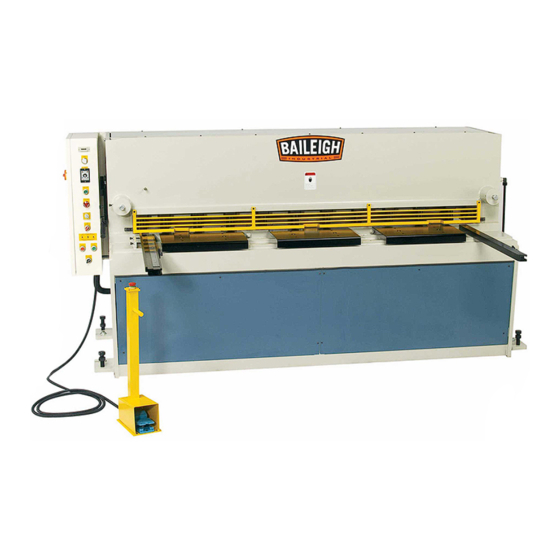
HYDRAULIC SHEAR
MODEL: SH-8003HD
Baileigh Industrial, Inc.
P.O. Box 531
Manitowoc, WI 54221-0531
Phone: 920.684.4990
Fax: 920.684.3944
sales@baileigh.com
© 2018 Baileigh Industrial, Inc.
Rev. 11/2018
Advertisement
Table of Contents

Related Manuals for Baileigh SH-8003HD


Summary of Contents for Baileigh SH-8003HD
- Page 1 REPRODUCTION OF THIS MANUAL IN ANY FORM WITHOUT WRITTEN APPROVAL OF BAILEIGH INDUSTRIAL, INC. IS PROHIBITED. Baileigh Industrial, Inc. does not assume and hereby disclaims any liability for any damage or loss caused by an omission or error in this Operator’s Manual, resulting from accident, negligence, or other occurrence.
-
Page 2: Table Of Contents
Table of Contents SAFETY INSTRUCTIONS ....................1 SAFETY PRECAUTIONS ....................3 Dear Valued Customer: ....................3 Electrical Enclosure Disconnect Switch ............... 6 Hazard Signs ....................... 6 MATERIAL SELECTION ....................7 MACHINE ADJUSTMENTS .................... 7 Blade Clearance ......................7 Suggested Knife Clearance ..................8 REPLACING THE SHEAR BLADES ................ -
Page 3: Safety Instructions
IMPORTANT PLEASE READ THIS OPERATORS MANUAL CAREFULLY It contains important safety information, instructions, and necessary operating procedures. The continual observance of these procedures will help increase your production and extend the life of the equipment. SAFETY INSTRUCTIONS LEARN TO RECOGNIZE SAFETY INFORMATION This is the safety alert symbol. - Page 4 SAVE THESE INSTRUCTIONS. Refer to them often and use them to instruct others. PROTECT EYES Wear safety glasses or suitable eye protection when working on or around machinery. HYDRAULIC HOSE FAILURE Exercise CAUTION around hydraulic hoses in case of a hose or fitting failure.
-
Page 5: Safety Precautions
Baileigh does not recommend or endorse making any modifications or alterations to a Baileigh machine. Modifications or alterations to a machine may pose a substantial risk of injury to the operator or others and may do substantial damage to the machine. - Page 6 1. FOR YOUR OWN SAFETY, READ INSTRUCTION MANUAL BEFORE OPERATING THE MACHINE. Learn the machine’s application and limitations as well as the specific hazards. 2. Only trained and qualified personnel can operate this machine. 3. Make sure guards are in place and in proper working order before operating machinery.
- Page 7 19. Store idle equipment. When not in use, tools must be stored in a dry location to inhibit rust. Always lock up tools and keep them out of reach of children. 20. DO NOT operate machine if under the influence of alcohol or drugs. Read warning labels on prescriptions.
-
Page 8: Electrical Enclosure Disconnect Switch
Electrical Enclosure Disconnect Switch WARNING: Before opening the door to work on electrical circuits, turn the main disconnect switch “OFF”. Also turn off and Lock Out the electrical supply source to this machine. FAILURE TO FOLLOW THESE INSTRUCTIONS MAY RESULT IN FATAL OR SERIOUS INJURY. -
Page 9: Material Selection
MATERIAL SELECTION CAUTION: It must be determined by the customer that materials being processed through the machine are NOT potentially hazardous to operator or personnel working nearby. When selecting materials keep these instructions in mind: • Material must be clean and dry. (without oil) •... -
Page 10: Suggested Knife Clearance
Suggested Knife Clearance Note: This is a general guide for setting the blade gap. Your specific settings may change based upon several factors regarding specific material and other machine settings and conditions. This is based upon a general guideline of blade gap is equal to 6.5%-7% of material thickness. -
Page 11: Replacing The Shear Blades
The blades on the Baileigh shear have multiple usable edges. If you have not already used both cutting edges on the top blade you can rotate it end for end to expose a sharp edge. The bottom blade has four usable edges. -
Page 12: To Rotate Or Replace The Top Blade
To Rotate or Replace the Top Blade CAUTION: Always wear proper eye protection with side shields, safety footwear, and leather gloves to protect from burrs and sharp edges. Keep hands and fingers clear of the shearing blade and clamping cylinders. 1. -
Page 13: To Rotate Or Replace The Bottom Blade
To Rotate or Replace the Bottom Blade CAUTION: Always wear proper eye protection with side shields, safety footwear, and leather gloves to protect from burrs and sharp edges. Keep hands and fingers clear of the shearing blade and clamping cylinders. 1. -
Page 14: Knife Bar Ways Adjustment
KNIFE BAR WAYS ADJUSTMENT The ram ways are adjustable to affect the wear that will occur during gears of service. The adjustment will only be required about every five (5) years, unless the shear is allowed to operate unleveled which causes a twisting action and premature ways wear. The proper running clearance is 0.0015”-0.0019”... -
Page 15: Lubrication And Maintenance
LUBRICATION AND MAINTENANCE WARNING: Make sure the electrical disconnect is OFF before working on the machine. Maintenance should be performed on a regular basis by qualified personnel. Always follow proper safety precautions when working on or around any machinery. Daily Maintenance •... -
Page 16: Hydraulic Oil
Hydraulic Oil The hydraulic oil is the primary medium for transmitting pressure and also must lubricate the running parts of the pump. After installation of the machine and before machine startup, bring the oil level up to 90% of capacity. Verify that the ram is in the upper most position to prevent overfilling of the tank. A shortage of hydraulic oil can cause hydraulic system breakdown and damage to major mechanical parts due to overheating. -
Page 17: Hydraulic Schematic
HYDRAULIC SCHEMATIC... -
Page 18: Manifold Block
MANIFOLD BLOCK... -
Page 19: Hydraulic Component Identification
Hydraulic Component Identification Item Description Part No. Motor 15hp (11.2kw), 480V, 3ph, 60hz HP*4P Pump VQ15-19-F-RRL-03 Strainer MF-08 Check Valve CV13A2050N Relief Valve RVCA LAN SGREN-IN Solenoid Valve SV08-21 Solenoid Valve DG4V-3-7C Solenoid Valve DG4V-3-6C Modular Pilot Operated Check Valve MPC-02W Logic Valve LODC XDN... -
Page 20: Electrical Enclosure Back Panel
ELECTRICAL ENCLOSURE BACK PANEL... -
Page 21: Electrical Component Identification
ELECTRICAL COMPONENT IDENTIFICATION TIMER STPY-M3 INCH AUTO LAMP MILD STEEL T.S 64000psi 20GA 10 GA 3/16" 14 GA 28GA 10GA STAINLESS T.S 100000psi... -
Page 22: Electrical Parts List
Electrical Parts List Item Description Part No. Main Switch P1-32 Magnetic Switch CU-22 Over Circuit Relay RHU-80KP 25A Transformer 1Ph, 240-480/110-24V Fuses 10 x 38mm @ 2A, 1A, 10A Power Supply DC 24V 8A 2200uf Power Supply RS-25-24 4" 110VAC R1 - R7 Power Relay MY-4 AC 24V RXM4LB1B7... -
Page 23: Electrical Schematic (Sheet. 1)
ELECTRICAL SCHEMATIC (Sheet. 1) LAMP... -
Page 24: Electrical Schematic (Sheet 2)
ELECTRICAL SCHEMATIC (Sheet 2) 24 VAC POWER (WHITE LAMP) MOTOR START (GREEN LAMP) TOP LIMIT SINGLE STROKE CONTINUOUS STROKE FOOT SWITCH STROKE TIMER (CUT LENGTH) TOP BEAM DOWN TOP BEAM CONTINUOUS TIMER ANGLE ADJ. (+) ANGLE ADJ. (-) -
Page 25: Electrical Schematic (Sheet 3)
ELECTRICAL SCHEMATIC (Sheet 3) 24 VAC BLADE ANGLE TOP LIMIT BLADE ANGLE ADJUSTMENT TB5 10 BLADE ANGLE MINIMUM LIMIT TB5 11 CUT QUANTITY DIRECTIONAL VALVE DIRECTIONAL VALVE " " " " " " " "... -
Page 26: Electrical Wire Terminals
ELECTRICAL WIRE TERMINALS... -
Page 27: Mechanical Replacement Parts
MECHANICAL REPLACEMENT PARTS Item Description Part No. Top sprocket Hardened Teeth Idler sprocket 20T Hardened Teeth Bottom sprocket Hardened Teeth Roller chain Grease fitting Roller wheel Roller wheel bearing Bearing wheel Shadow wire (by the foot) Hold down rubber pad SH8010 Wire Shown with guards removed. -
Page 28: Main Frame Parts Diagram
MAIN FRAME PARTS DIAGRAM... -
Page 31: Main Frame Parts List
Main Frame Parts List Item Description Bottom Beam Assy. Screw Upper Knife Bearing Bearing Shaft Bearing Block Washer Division Plate Bearing Block Cover Screw Side Gauge Screw Screw Screw Supporting Arm Screw Hold Down Screw Table Plate Steel Ball Screw Knife Clearance Indicate Handle Chain Sprocket Shaft Screw... - Page 32 Item Description Chain Sprocket Shaft Shaft Filler Washer Screw Screw Chain Adjuster Chain Sprocket Bearing Bearing Shaft Snap Ring Adjusting Block Screw Washer Adjusting Screw Screw Lower Knife Screw Wear Plate Screw Screw Bearing Shaft Bearing Screw Stool Plate Screw Cylinder Pin Cylinder Screw...
-
Page 33: Hydraulic Cylinder-Parts Diagram
HYDRAULIC CYLINDER-PARTS DIAGRAM... -
Page 34: Hydraulic Cylinder Parts List
Hydraulic Cylinder Parts List Item Description Cylinder Body Air Bleed Screw (large cylinder only) Piston Inner Rod End Gland Clevis (Rod End) Link Shaft (Up) Socket Head Screw 5/16 x .75" Long Washer Socket Head Screw 3/8 x 1.00" Long Link Shaft (Down) Washer Socket Head Screw 3/8"... -
Page 35: Hold Down Cylinder Parts Diagram
HOLD DOWN CYLINDER PARTS DIAGRAM Hold Down Cylinder Parts List Item Description Rubber Pad Socket Head Screw 5/16 x .75" Long Cover Oil Seal Cylinder Pipe Piston Rod Spring Dual Backup Ring Washer Washer Socket Head Screw 5/16 x .75" Long... -
Page 36: Back Gauge Parts Diagram
BACK GAUGE PARTS DIAGRAM... -
Page 37: Back Gauge Parts List
Back Gauge Parts List Item Description Hand Wheel Bearing Rack Wheel-Right Side Rack Block Sleeve Coupling Set Screw Coupling Shaft Locking Shaft Washer Plastic Handle Slotted Head Screw Shaft Filler Washer Adjusting Rod Angle Stopper Screw Screw Shaft Filler Washer Bearing Rack Rod Shaft Filler Washer... -
Page 38: Troubleshooting
TROUBLESHOOTING WARNING: Make sure the electrical disconnect is OFF before working on the machine. SYMPTOM POSSIBLE CAUSE (S) CORRECTIVE ACTION No power. Check the power source. Disconnect switch not turned on. Turn the switch to ON position. Emergency button not reset. Release the emergency buttons by turning the knob to the right. - Page 39 SYMPTOM POSSIBLE CAUSE (S) CORRECTIVE ACTION Relief valve not set correctly. Check hydraulic pressure and adjust relief valve (tighten to increase pressure). Relief valve damaged. Replace relief valve. Machine moves, but cannot reach Pump damaged. Replace pump capacity. Internal cylinder leak. Contact dealer for service.
- Page 40 , WI 54220 UFEK RIVE ANITOWOC : 920. 684. 4990 F : 920. 684. 3944 HONE www.baileigh.com BAILEIGH INDUSTRIAL, INC. 1455 S. C , CA 91761 AMPUS VENUE NTARIO : 920. 684. 4990 F : 920. 684. 3944 HONE BAILEIGH INDUSTRIAL LTD. U...
Need help?
Do you have a question about the SH-8003HD and is the answer not in the manual?
Questions and answers