Table of Contents
Advertisement
Quick Links
OPERATOR'S MANUAL
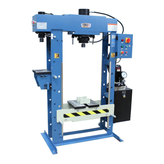
60/15 TON HYDRAULIC SHOP PRESS
MODEL: HSP-60M-C
Baileigh Industrial Holdings LLC
P.O. Box 531
Manitowoc, WI 54221-0531
Phone: 920.684.4990
Fax: 920.684.3944
sales@baileigh.com
REPRODUCTION OF THIS MANUAL IN ANY FORM WITHOUT WRITTEN APPROVAL OF BAILEIGH INDUSTRIAL
HOLDINGS LLC IS PROHIBITED. Baileigh Industrial Holdings LLC, Inc. does not assume and hereby disclaims any
liability for any damage or loss caused by an omission or error in this Operator's Manual, resulting from accident,
negligence, or other occurrence.
Rev. 08/2020
© 2020 Baileigh Industrial Holdings LLC
Advertisement
Table of Contents

Related Manuals for Baileigh HSP-60M-C


Summary of Contents for Baileigh HSP-60M-C
- Page 1 REPRODUCTION OF THIS MANUAL IN ANY FORM WITHOUT WRITTEN APPROVAL OF BAILEIGH INDUSTRIAL HOLDINGS LLC IS PROHIBITED. Baileigh Industrial Holdings LLC, Inc. does not assume and hereby disclaims any liability for any damage or loss caused by an omission or error in this Operator’s Manual, resulting from accident, negligence, or other occurrence.
-
Page 2: Table Of Contents
Table of Contents THANK YOU & WARRANTY ..................1 INTRODUCTION ......................3 GENERAL NOTES ......................3 SAFETY INSTRUCTIONS ....................4 SAFETY PRECAUTIONS ....................7 Dear Valued Customer: ....................7 TECHNICAL SUPPORT ....................9 TECHNICAL SPECIFICATIONS ................... 10 UNPACKING AND CHECKING CONTENTS ..............11 TRANSPORTING AND LIFTING .................. - Page 3 SIDE RAM PARTS DIAGRAM ..................39 Side Ram Parts List ....................40 HYDRAULIC PUMP PARTS DIAGRAM ............... 41 Hydraulic Pump Parts List ..................41 ELECTRICAL SCHEMATIC ..................42 HYDRAULIC DIAGRAM ....................43 TROUBLESHOOTING ....................44...
-
Page 4: Thank You & Warranty
THANK YOU & WARRANTY Thank you for your purchase of a machine from Baileigh Industrial Holdings LLC. We hope that you find it productive and useful to you for a long time to come. Inspection & Acceptance. Buyer shall inspect all Goods within ten (10) days after receipt thereof. Buyer’s payment shall constitute final acceptance of the Goods and shall act as a waiver of the Buyer’s rights to inspect or... - Page 5 We apologize for any discrepancies that may occur. Baileigh Industrial Holdings LLC reserves the right to make any and all changes deemed necessary in the course of business including but not limited to pricing, product specifications, quantities, and product availability.
-
Page 6: Introduction
INTRODUCTION The quality and reliability of the components assembled on a Baileigh Industrial Holdings LLC machine guarantee near perfect functioning, free from problems, even under the most demanding working conditions. However, if a situation arises, refer to the manual first. If a solution cannot be found, contact the distributor where you purchased our product. -
Page 7: Safety Instructions
IMPORTANT PLEASE READ THIS OPERATORS MANUAL CAREFULLY It contains important safety information, instructions, and necessary operating procedures. The continual observance of these procedures will help increase your production and extend the life of the equipment. SAFETY INSTRUCTIONS LEARN TO RECOGNIZE SAFETY INFORMATION This is the safety alert symbol. - Page 8 SAVE THESE INSTRUCTIONS. Refer to them often and use them to instruct others. PROTECT EYES Wear safety glasses or suitable eye protection when working on or around machinery. PROTECT AGAINST NOISE Prolonged exposure to loud noise can cause impairment or loss of hearing.
- Page 9 HIGH VOLTAGE USE CAUTION IN HIGH VOLTAGE AREAS. DO NOT assume the power to be off. FOLLOW PROPER LOCKOUT PROCEDURES. EMERGENCY STOP BUTTON In the event of incorrect operation or dangerous conditions, the machine can be stopped immediately by pressing the E-STOP button. Twist the emergency stop button clockwise (cw) to reset.
-
Page 10: Safety Precautions
Baileigh does not recommend or endorse making any modifications or alterations to a Baileigh machine. Modifications or alterations to a machine may pose a substantial risk of injury to the operator or others and may do substantial damage to the machine. - Page 11 7. Dressing material edges. Always chamfer and deburr all sharp edges. 8. Do not force tool. Your machine will do a better and safer job if used as intended. DO NOT use inappropriate attachments in an attempt to exceed the machine’s rated capacity. 9.
-
Page 12: Technical Support
(other than die sets and blades). For specific application needs or future machine purchases contact the Sales Department at: sales@baileigh.com, Phone: 920.684.4990, or Fax: 920.684.3944. Note: The photos and illustrations used in this manual are representative only and may not depict the actual color, labeling or accessories and may be intended to illustrate technique only. -
Page 13: Technical Specifications
TECHNICAL SPECIFICATIONS Main Bed, Maximum Capacity 60 ton (54 ton) Main Working Speed - Ram Extension .32" / sec. (8.1mm/sec.) Main Return Speed - Ram Retraction .40" / sec. (10mm/sec.) Main Cylinder Stroke 11.8" (300mm) Main Working Width 41.3" (1050mm) Main Cylinder Diameter 7.55"... -
Page 14: Unpacking And Checking Contents
UNPACKING AND CHECKING CONTENTS Your Baileigh machine is shipped complete. Separate all parts from the packing material and check each item carefully. Make certain all items are accounted for before discarding any packing material. WARNING: SUFFOCATION HAZARD! Immediately discard any plastic bags and packing materials to eliminate choking and suffocation hazards to children and animals. -
Page 15: Transporting And Lifting
TRANSPORTING AND LIFTING NOTICE: Lifting and carrying operations should be carried out by skilled workers, such as a truck operator, crane operator, etc. If a crane is used to lift the machine, attach the lifting chain carefully, making sure the machine is well balanced. Follow these guidelines when lifting with truck or trolley: •... -
Page 16: Installation
INSTALLATION IMPORTANT: Consider the following when looking for a suitable location to place the machine: • Overall weight of the machine. • Weight of material being processed. • Sizes of material to be processed through the machine. • Space needed for auxiliary stands, work tables, or other machinery. •... - Page 17 WARNING: Before operating the press, make sure it is firmly anchored the floor. If it tips over on you, it could cause severe injury or death. Deliver condition The press is delivered in the following condition: • Table in lowest position •...
-
Page 18: Getting To Know Your Machine
GETTING TO KNOW YOUR MACHINE Note: The photos and illustrations used in this manual are representative only and may not depict the actual color, labeling or accessories and may be intended to illustrate technique only. - Page 19 Item Description Main Table Support Pins; Supports the worktable at the desired work height. Main Worktable: Moveable table to raise or lower to support the material to be pressed. Main Frame; Supports the entire machine components and work material. Heal Blocks and V-Blocks; used to support the material during the pressing operation. Main Cylinder Head: Removable head which presses against the work material.
-
Page 20: Assembly And Set Up
ASSEMBLY AND SET UP WARNING: For your own safety, DO NOT connect the machine to the power source until the machine is completely assembled and you read and understand the entire instruction manual. Note: The hydraulic unit weights about 90lbs (41kg). For placing the unit in the correct position, use and assistant or safe lifting equipment to lift the unit. - Page 21 6. Route the main cylinder hydraulic hoses (C) to the hydraulic fitting and matching the letter labels (A to A and B to B), one at a time, remove the plastic caps and install the hoses to the fittings. Tighten securely, however do not over tighten and distort the swivel fitting collar.
- Page 22 12. Remove the electrical cabinet from the packaging and using the three screws (E) installed in the right side of the frame, mount the cabinet to the frame and tighten securely. 13. Open the cabinet and route the wires from the motor into the bottom of the electrical cabinet and secure the strain relief (E) into the cabinet.
-
Page 23: Electrical
3-phase power source other than direct 3-phase. If you are using an alternate power source, consult a certified electrician or contact Baileigh Industrial Holdings LLC prior to energizing the machine. CAUTION: HAVE ELECTRICAL UTILITIES CONNECTED TO MACHINE BY A CERTIFIED ELECTRICIAN! Check if the available power supply is the same as listed on the machine nameplate. -
Page 24: Power Cord Connection
WARNING: In all cases, make certain the receptacle in question is properly grounded. If you are not sure, have a qualified electrician check the receptacle • Improper connection of the equipment-grounding conductor can result in risk of electric shock. The conductor with insulation having an outer surface that is green with or without yellow stripes is the equipment-grounding conductor. -
Page 25: Operation Preplanning
OPERATION PREPLANNING This is a general discussion on press operation and is not intended to be an exact step-by-step procedure. This is intended to create a broad thought process to be considered prior to using the press to stimulate the operator into thinking about as many possible scenarios that could cause injury or material damage. -
Page 26: General Information
• Fasteners and Retainers: Make sure that all retaining rings, pins, or fasteners are removed, and no hidden secondary retainers are present. • Hidden Objects: Some components house one or more pieces such and springs, retaining rings, or spacers. Make sure that the part to be dismantled with the press has the applicable caging system to catch hidden items. -
Page 27: Press Functions
PRESS FUNCTIONS Main Disconnect Switch The main disconnect switch is located on the front of the electrical cabinet. • Turn the switch to the ON position to supply power to the electrical controls. The red indicator will light up as long as the disconnect is ON. -
Page 28: Pressure Regulation Valve
PRESSURE REGULATION VALVE CAUTION: NEVER EXCEED THE MAXIMUM PRESSURE SETTING FOR THE RAM BEING USED! The pressure regulation valve (A) is located in the top cover of the hydraulic unit. With this valve the maximum pressure, referring to the maximum press capacity, can be changed. Turning the knob clockwise will increase the pressure, turning the knob counterclockwise will decrease the pressure. -
Page 29: Main Cylinder Direction Control Valve
8. When the pressure is set, hold the knob in position and lightly tighten the lock nut to hold the knob and prevent inadvertent pressure changes. Main Cylinder Direction Control Valve The selector valve and the main direction control valves are located on the top cover of the hydraulic unit. -
Page 30: Side Cylinder Direction Control Valve
Side Cylinder Direction Control Valve CAUTION: NEVER EXCEED THE MAXIMUM PRESSURE SETTING! The Selector valve is a 2-position switching valve located on the top cover of the hydraulic unit. It is used to direct and oil flow to either the main cylinder directional valve, or to the side cylinder directional valve. -
Page 31: Cylinder Positioning
4. If not already fully retracted, use the directional control valve to fully retract the ram. 5. Extend the ram to the fully lowered position. 6. Now fully retract the ram. 7. Repeat this complete cycle at least 6 times to be sure all air is out of the system. 8. - Page 32 Table Adjustment IMPORTANT: NEVER lift or lower the table with tooling or material or pressure from the ram on the table. This will damage the machine voiding the warranty. Lifting the table is performed using the lifting chain attached from the ram to the table. 1.
-
Page 33: Operation
OPERATION CAUTION: Always wear proper eye protection with side shields, safety footwear, and leather gloves to protect from burrs and sharp edges. 1. Place the work piece on the table so that it is aligned with the piston rod. If this is not possible, reposition the cylinder to achieve the best alignment. -
Page 34: Understanding Springback
UNDERSTANDING SPRINGBACK Springback, also known as elastic recovery, is the result of the metal wanting to return to its original shape after undergoing compression and stretch. After the bending leaf is removed from the metal and the load is released, the piece part relaxes, forcing the bent portion of the metal to return slightly to its original shape. -
Page 35: Lubrication And Maintenance
LUBRICATION AND MAINTENANCE WARNING: Make sure the electrical disconnect is OFF before working on the machine. Maintenance should be performed on a regular basis by qualified personnel. Always follow proper safety precautions when working on or around any machinery. Note: Proper maintenance can increase the life expectancy of your machine. Daily Maintenance •... -
Page 36: Changing The Hydraulic Oil
Yearly Maintenance • Replace the hydraulic oil of the unit. Changing the Hydraulic Oil The hydraulic oil is the primary medium for transmitting pressure and also must lubricate the running parts of the pump. Replace the hydraulic oil at least once a year. 1. -
Page 37: Overall Machine Parts Diagram
OVERALL MACHINE PARTS DIAGRAM... -
Page 38: Overall Machine Parts List
Overall Machine Parts List Item Item Description Qty. HSP60MC-1 Electric Pump HSP60MC-2 Electric Motor HSP60MC-3 Electric Box HSP60MC-4 Nut M12 HSP60MC-5 Frame HSP60MC-6 Pump Assembly Bolt M12×90 HSP60MC-7 Heal Block HSP60MC-8 Fixed Rod HSP60MC-9 Chain Rod HSP60MC-10 HSP60MC-11 Ram Assembly Plate HSP60MC-12 Hexangular Bolt M12×80 HSP60MC-13... - Page 39 Item Item Description Qty. HSP60MC-34 Side Ram Assembly HSP60MC-35 Washer 12mm HSP60MC-36 Bolt M12*45 HSP60MC-37 Bolt M10*40 HSP60MC-38 Side Ram Table HSP60MC-39 Side Ram Table Base HSP60MC-40 Bolt M16*50 HSP60MC-41 Plate HSP60MC-42 Washer 12mm HSP60MC-43 Bolt M12*40...
-
Page 40: Main Ram Parts Diagram
MAIN RAM PARTS DIAGRAM... -
Page 41: Main Ram Parts List
Main Ram Parts List Item Part No. Description Qty. HSP60MC-R1 Cylinder HSP60MC-R2 O Ring Ø10 HSP60MC-R3 HSP60MC-R4 Oil Hose Connecter HSP60MC-R5 O Ring18×2.4 HSP60MC-R6 Circlip 50 HSP60MC-R7 Ring Cap HSP60MC-R8 Seal Ring HSP60MC-R9 Piston Head HSP60MC-R10 Seal Ring HSP60MC-R11 Seal Ring 20×3×499 HSP60MC-R12 Seal Ring 160×5.7 HSP60MC-R13... -
Page 42: Side Ram Parts Diagram
SIDE RAM PARTS DIAGRAM... -
Page 43: Side Ram Parts List
Side Ram Parts List Item Part No. Description Qty. HSP60MC-SR1 Seal Bolt HSP60MC-SR2 Oil Hose Connecter 1 HSP60MC-SR3 O Ring 22*2.4 HSP60MC-SR4 Cylinder HSP60MC-SR5 Nut M20 HSP60MC-SR6 Split Washer 20 HSP60MC-SR7 Piston Head HSP60MC-SR8 Seal Ring 100 HSP60MC-SR9 Seal Ring Holder SR10 HSP60MC-SR10 Seal Ring 8*2*312... -
Page 44: Hydraulic Pump Parts Diagram
HYDRAULIC PUMP PARTS DIAGRAM Hydraulic Pump Parts List Item Part No. Description Qty. HSP60MC-P1 Oil Tank HSP60MC-P2 Oil Gauge HSP60MC-P3 Oil Filter HSP60MC-P4 Piston Pump HSP60MC-P5 Electric Motor HSP60MC-P6 Pressure Gauge HSP60MC-P7 Ram Working Choose Valve HSP60MC-P8 Main Ram Hand Operated Valve HSP60MC-P9 Pump Pressure Adjust Valve... -
Page 45: Electrical Schematic
ELECTRICAL SCHEMATIC... -
Page 46: Hydraulic Diagram
HYDRAULIC DIAGRAM... -
Page 47: Troubleshooting
TROUBLESHOOTING WARNING: Make sure the electrical disconnect is OFF before working on the machine. FAULT PROBABLE CAUSE REMEDY Check pressure gauge. Repair or replace as needed. Gauge Failure Clean valve(s). Replace if Plugged oil passage in relief needed. valve or check valve. Low Pressure Check and tighten any loose or Oil leak at hose fittings. - Page 48 BAILEIGH INDUSTRIAL HOLDINGS LLC 1625 D , WI 54220 UFEK RIVE ANITOWOC : 920. 684. 4990 F : 920. 684. 3944 HONE www.baileigh.com BAILEIGH INDUSTRIAL HOLDINGS LTD. U WIFT OINT WIFT ALLEY NDUSTRIAL STATE UGBY , CV21 1QH U IDLANDS...
Need help?
Do you have a question about the HSP-60M-C and is the answer not in the manual?
Questions and answers