Table of Contents
Advertisement
Quick Links
OPERATOR'S
MANUAL
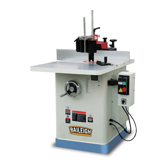
SPINDLE SHAPER
MODEL: SS-2822
Baileigh Industrial, Inc.
P.O. Box 531
Manitowoc, WI 54221-0531
Phone: 920.684.4990
Fax: 920.684.3944
sales@baileigh.com
REPRODUCTION OF THIS MANUAL IN ANY FORM WITHOUT WRITTEN APPROVAL OF BAILEIGH INDUSTRIAL, INC.
IS PROHIBITED. Baileigh Industrial, Inc. does not assume and hereby disclaims any liability for any damage or loss
caused by an omission or error in this Operator's Manual, resulting from accident, negligence, or other occurrence.
Rev. 04/2016
© 2016 Baileigh Industrial, Inc.
Advertisement
Table of Contents

Related Manuals for Baileigh SS-2822


Summary of Contents for Baileigh SS-2822
- Page 1 REPRODUCTION OF THIS MANUAL IN ANY FORM WITHOUT WRITTEN APPROVAL OF BAILEIGH INDUSTRIAL, INC. IS PROHIBITED. Baileigh Industrial, Inc. does not assume and hereby disclaims any liability for any damage or loss caused by an omission or error in this Operator’s Manual, resulting from accident, negligence, or other occurrence.
-
Page 2: Table Of Contents
Table of Contents THANK YOU & WARRANTY ..................1 INTRODUCTION ......................3 GENERAL NOTES ......................3 SAFETY INSTRUCTIONS ....................4 Dear Valued Customer: ....................6 SAFETY PRECAUTIONS ....................7 SPECIFICATIONS ......................12 TECHNICAL SUPPORT ....................12 UNPACKING AND CHECKING CONTENTS ..............13 Cleaning ........................ - Page 3 CONTOUR EDGE SHAPING WITH COLLAR BEARING .......... 37 ENCLOSED EDGE SHAPING ................... 40 TEMPLATES ......................41 PIECED TEMPLATE ....................41 SECURING THE TEMPLATE..................41 HORIZONTAL TOGGLE CLAMP ................42 SPECIAL CUTS ......................42 STACKED CUTTERS ....................42 SASH AND DOOR SHAPING ................... 43 BUTT JOINTS ......................
-
Page 4: Thank You & Warranty
THANK YOU & WARRANTY Thank you for your purchase of a machine from Baileigh Industrial. We hope that you find it productive and useful to you for a long time to come. Inspection & Acceptance. Buyer shall inspect all Goods within ten (10) days after receipt thereof. Buyer’s payment shall constitute final acceptance of the Goods and shall act as a waiver of the Buyer’s rights to inspect or... - Page 5 Baileigh Industrial makes every effort to ensure that our posted specifications, images, pricing and product availability are as correct and timely as possible. We apologize for any discrepancies that may occur. Baileigh Industrial reserves the right to make any and all changes deemed necessary in the course of business including but not limited to pricing, product specifications, quantities, and product availability.
-
Page 6: Introduction
After receiving your equipment remove the protective container. Do a complete visual inspection, and if damage is noted, photograph it for insurance claims and contact your carrier at once, requesting inspection. Also contact Baileigh Industrial and inform them of the unexpected occurrence. Temporarily suspend installation. -
Page 7: Safety Instructions
IMPORTANT PLEASE READ THIS OPERATORS MANUAL CAREFULLY It contains important safety information, instructions, and necessary operating procedures. The continual observance of these procedures will help increase your production and extend the life of the equipment. SAFETY INSTRUCTIONS LEARN TO RECOGNIZE SAFETY INFORMATION This is the safety alert symbol. - Page 8 SAVE THESE INSTRUCTIONS. Refer to them often and use them to instruct others. PROTECT EYES Wear safety glasses or suitable eye protection when working on or around machinery. PROTECT AGAINST NOISE Prolonged exposure to loud noise can cause impairment or loss of hearing.
-
Page 9: Dear Valued Customer
All Baileigh woodworking machines should be used only for their intended use. Baileigh does not recommend or endorse making any modifications or alterations to a Baileigh machine. Modifications or alterations to a machine may pose a substantial risk of injury to the operator or others and may do substantial damage to the machine. -
Page 10: Safety Precautions
SAFETY PRECAUTIONS Wood working can be dangerous if safe and proper operating procedures are not followed. As with all machinery, there are certain hazards involved with the operation of the product. Using the machine with respect and caution will considerably lessen the possibility of personal injury. However, if normal safety precautions are overlooked or ignored, personal injury to the operator may result. - Page 11 11. Stock Condition. ALWAYS inspect stock for staples, nails, knots, and other imperfections that could become projectiles or cause kickback resulting in serious bodily harm. Warped stock should be run through a jointer before you run it through the shaper. 12.
- Page 12 28. Maintain machine in top condition. Keep clean for best and safest performance. Follow instructions for lubricating and changing accessories. 29. Reduce the risk of unintentional starting. Make sure switch is in “OFF” position before plugging in power cord. 30. Never leave machine running unattended. TURN POWER OFF. Don’t leave machine until it comes to a complete stop.
- Page 13 BLIND CUT. When blind cutting, the workpiece is positioned on top of the template. This keeps the cutter(s) cutting only the underside of the workpiece and providing a “distance” guard for the operator. STOCK FEED. Stock opposite to the direction of the cutter rotation.
- Page 14 DO NOT REACH over shaper. There is danger of kickback which can pull the hand back into the cutter. Use push sticks to assist in pushing the work through. See Figure 4. A push block and/or a push stick must be used if the workpieces is less than 5”...
-
Page 15: Specifications
(other than die sets and blades). For specific application needs or future machine purchases contact the Sales Department at: sales@baileigh.com, Phone: 920.684.4990, or Fax: 920.684.3944. Note: The photos and illustrations used in this manual are representative only and may not depict the actual color, labeling or accessories and may be intended to illustrate technique only. -
Page 16: Unpacking And Checking Contents
UNPACKING AND CHECKING CONTENTS Your Baileigh machine is shipped complete. Separate all parts from the packing material and check each item carefully. Make certain all items are accounted for before discarding any packing material. WARNING: SUFFOCATION HAZARD! Immediately discard any plastic bags and packing materials to eliminate choking and suffocation hazards to children and animals. -
Page 17: Cleaning
Cleaning WARNING: DO NOT USE gasoline or other petroleum products to clean the machine. They have low flash points and can explode or cause fire. CAUTION: When using cleaning solvents work in a well-ventilated area. Many cleaning solvents are toxic if inhaled. Your machine may be shipped with a rustproof waxy coating and/or grease on the exposed unpainted metal surfaces. -
Page 18: Transporting And Lifting
TRANSPORTING AND LIFTING IMPORTANT: Lifting and carrying operations should be carried out by skilled workers, such as a truck operator, crane operator, etc. If a crane is used to lift the machine, attach the lifting chain carefully, making sure the machine is well balanced. Follow these guidelines when lifting with truck or trolley: ... -
Page 19: Installation
INSTALLATION IMPORTANT: Consider the following when looking for a suitable location to place the machine: Overall weight of the machine. Weight of material being processed. Sizes of material to be processed through the machine. Space needed for auxiliary stands, work tables, or other machinery. ... -
Page 20: Geting To Know Your Machine
GETING TO KNOW YOUR MACHINE Raise/Lower Handwheel Motor Cover Scale Forward/Reverse Switch Power Switch Fence Assembly Table Extension Table Arbor Stabilizer Knob Miter Gauge (not shown) -
Page 21: Assembly
ASSEMBLY WARNING: For your own safety, DO NOT connect the machine to the power source until the machine is completely assembled and you read and understand the entire instruction manual. Remove Shipping Brace There is a metal strap (A) located inside of the cabinet that is bolted to both the motor and the cabinet to help prevent damage during shipping. -
Page 22: Handle Installation
Handle Installation The handwheel is used to raise and lower the spindle. 1. Install the handle to the handwheel, (Fig. 7). Fig. 7 Extension Wings Installation The shaper has one extension wing that needs to be mounted before it can be operated. 1. - Page 23 3. Insert the draw bar (A) through the bottom of the quill, making sure that the beveled edge of the drawbar nut (B) is facing upwards. (Fig. 10) Fig. 10 4. Use the spindle wrench to hold the top flats on the spindle while tightening the draw bar nut using an open end wrench.
-
Page 24: Setting Table Inserts
Setting Table Inserts The table inserts are preinstalled at the factory. They should be adjusted so that the top surface of the insert is level with the tabletop. If any adjustment is necessary: 1. Remove the three screws in the top of the insert. 2. -
Page 25: Assembling Fence
6. Replace spindle nuts (A) and tighten using the spindle wrenches. The spindle structure is as shown in Fig. 13-1, the cutter is locked with a cap screw M10 x 30. Fig. 13-1 Assembling Fence 1. Install the fence by placing the main fence casting (A) on the table surface. -
Page 26: Dust Collection
4. Repeat steps 3 to attach the remaining fence half. 5. Attach Guard Mounting Bracket (F) to the red top Cover with knob (G, Fig. 16). 6. There are several types of guards that should be attached to the shaper fence depending on the operation that you are performing. -
Page 27: Electrical
ELECTRICAL CAUTION: HAVE ELECTRICAL UTILITIES CONNECTED TO MACHINE BY A CERTIFIED ELECTRICIAN! Check if the available power supply is the same as listed on the machine nameplate. WARNING: Make sure the grounding wire (green) is properly connected to avoid electric shock. DO NOT switch the position of the green grounding wire if any electrical plug wires are switched during hookup. -
Page 28: Power Cord Connection
Improper connection of the equipment-grounding conductor can result in risk of electric shock. The conductor with insulation having an outer surface that is green with or without yellow stripes is the equipment-grounding conductor. If repair or replacement of the electric cord or plug is necessary, do not connect the equipment-grounding conductor to a live terminal. -
Page 29: Electrical Schematic
Electrical Schematic... -
Page 30: Adjustments
ADJUSTMENTS Check all mounting screws and bolts to see that they are tight. CAUTION: When changing tools, adjusting the drive belt, or doing cleanup and maintenance, always turn the machine off and unplug the machine from its power source. Changing Speeds This shaper is constructed with a 3 step pulley on both the motor pulley (A) and on the spindle pulley (B). -
Page 31: Fence Positioning & Alignment
Fence Positioning & Alignment Fence Positioning The two faces of the fence are independent of one another and can be set at different positions to allow for different shaping tasks. To adjust 1. Loosen lock lever (A, Fig. 20). 2. Adjust the position of the fence by turning the adjustment knob (B) 3. -
Page 32: Belt Tension
Belt Tension The belt tension is set at the factory and should not need adjustment on initial setup. The belt will need occasional adjustment as the belt will stretch over time. The belt should yield 1/4” of deflection when squeezed together at the midpoint. 1. -
Page 33: Before Operating
BEFORE OPERATING Turn the motor on momentarily to check for proper rotation. The spindle should rotate counterclockwise when looking down on the spindle. Correct as required. Run the machine for a short period of time to insure that the moving parts are working properly with no excessive vibration. -
Page 34: Switch Operation
Switch Operation Do not turn the shaper on until all assembly and adjustment instructions have been completed. NEVER start the shaper with material on the table! 1. To start the shaper, press the green start button (A). 2. To stop the shaper, press the red emergency stop button (B). 3. -
Page 35: Using Collars
Using Collars When shaping workpieces that have irregular shapes, it is essential to use a collar. There are three basic types setup for the collar. Each setup has advantages and disadvantages. Below the Cutter The advantage of the collar being positioned below the cutter is that the user can see the progress of the cut. -
Page 36: Counterclock Wise Setup
Counterclock Wise Setup With the cutter installed as shown, feed the workpiece from right-to-left. Clock Wise Setup With the cutter installed as shown, feed the workpiece from left-to-right. GRAIN DIRECTION Plan to shape the work piece in the same direction as the grain when possible. Some open grain woods (such as redwood, fir, and oak) will leave a rough, or slightly splintered edge when cut against the grain. -
Page 37: Straight Edge Shaping
STRAIGHT EDGE SHAPING Straightedge shaping is always performed with the work piece against the fence. To set up: 1. UNPLUG OR DISCONNECT SHAPER FROM POWER SOURCE AND LOCK OUT POWER. 2. Check to see that the fence faces are parallel, properly in line or offset if necessary, and securely tightened. -
Page 38: Edge Shaping: Long Boards
EDGE SHAPING: LONG BOARDS When edge shaping long boards, the work piece must be at least 12 inches long. 1. Use the hold-ins and hold-downs as shown in figure 13 to firmly hold the work piece down and against the fence. If work piece is too wide for the hold-ins to be used, clamp a scrap board to the table to substitute for the hold-ins. -
Page 39: End Shaping
END SHAPING WARNING: End shaping a narrow workpiece without a special guide could result in the workpiece rocking into the cutterhead causing minor, or major, personal injury. When end shaping narrow stock, it is important that at least one half of the workpiece end be in contact with either the infeed or outfeed fence as shown in Figure 15. -
Page 40: Straightline Bevel Edge Shaping
STRAIGHTLINE BEVEL EDGE SHAPING To perform a bevel edge cut, the infeed edge of the jig is placed against the infeed fence and clamped to the table, as shown in Figure 18. The outfeed fence is moved forward as necessary to compensate for the cut. - Page 41 Note: Since the collar requires at least 1/8" of surface edge to ride against, the entire edge cannot be shaped as shown in Figure 21. The use of a pattern, however, permits the shaping of the entire contour edge. If the workpiece is to be shaped all around the perimeter, hold it firmly and push the work straight into the cutter until the depth of cut is established by the collar as shown in Figure 22.
- Page 42 Large circular and arc-shaped stock can be shaped as described under “CONTOUR EDGE SHAPING”; however, small sized stock requires the use of special shaping jigs similar to those shown in Figure 24 and 25. With the entire fence assembly removed, carefully position the jig for desired depth of cut and securely clamp to the table.
-
Page 43: Enclosed Edge Shaping
ENCLOSED EDGE SHAPING WARNING: Enclosed edge shaping is extremely dangerous. The operator must be aware at all times of the direction of feed. WARNING: Unless the workpiece is attached to a larger wooden base, NEVER perform enclosed edge shaping if there is less than 12” of workpiece material all around the opening. -
Page 44: Templates
TEMPLATES The template, which is usually made of 3/4” scrap material, must be thick enough to provide a solid bearing edge against a collar. When constructing a template similar to the one shown in Figure 28, keep in mind that it serves only as a guide for the cutter. -
Page 45: Horizontal Toggle Clamp
In many situations the workpiece is positioned against the template using dowels as anchor points and handles (wood blocks) to assist the operator in guiding the workpiece through the cut as shown in Figure 31. HORIZONTAL TOGGLE CLAMP The horizontal toggle clamp, similar to those illustrated in Figure 32, is especially useful when ordinary “C”... -
Page 46: Sash And Door Shaping
SASH AND DOOR SHAPING Shaping a door still requires two operations. Figure 33 shows the sash cut for the first operation. Figure 34 shows the stock flipped over and the sash cutter used with a 1/4" groove cutter to complete the cut. Figure 35 shows the first shaping cut with the sash cutter for the matching door stile sash. -
Page 47: Butt Joints
Figure 37 shows the first shaping out for a window-sash stile utilizing a sash cutter, collar, collar, and a 1/2" groove cutter. Figure 38 shows both cuts required for a window-sash rail end. The first operation at top is a rabbet cut made with a groove cutter. -
Page 48: Taper Cuts
TAPER CUTS Offsetting the Fences CAUTION: Do not use the standard fence for short work (12 inches or less in length on the side to be cut). Instead, use a miter gauge or special fixture to avoid losing control of the workpiece. Taper cuts can be made by offsetting the fences for the amount of taper desired, or with a layout line on the stock which can be made parallel to the infeed fence as shown in... -
Page 49: Tenoning
TENONING The tenoning fixture illustrated in Figure 43 shows a miter gauge equipped with a hold-down for shaping the ends of narrow workpieces. The miter gauge can also be adapted to cut square and centered tenons at the ends of legs for tables, chairs, etc. -
Page 50: Maintenance
MAINTENANCE WARNING: Make sure the electrical disconnect is OFF before working on the machine. Maintenance should be performed on a regular basis following proper safety precautions. This shaper requires very little maintenance other than minor lubrication and cleaning. The following sections detail what will need to be done in order to assure continued operation of your saw. -
Page 51: Troubleshooting
TROUBLESHOOTING WARNING: Make sure the electrical disconnect is OFF before working on the machine. Trouble Possible Cause Remedy 1. Cord unplugged from the power 1. Plug in power cord. source. 2. Replace fuse or reset circuit 2. Fuse blown or circuited breaker breaker. - Page 52 Trouble Possible Cause Remedy 1. Stand on uneven surface. 1. Stand must rest solidly on level 2. Cutterhead damaged. surface. Fasten to floor if necessary. 3. Defective V-belt. 2. Replace cutterhead. 4. V-belt incorrectly tensioned. 3. Replace V-belt. Machine vibrates. 5.
-
Page 53: Body Parts Diagram
BODY PARTS DIAGRAM... -
Page 54: Body Parts List
Body Parts List REF# DESCRIPTION REF# DESCRIPTION Table insert Nut 8 O ring Tapping screw ST4.8X16 Table insert Lock cover O ring Lock nut 8 Scale Cap screw M5x20 Pan HD screw M8x20 Set screw Shipping strip Table insert Ⅰ Flat washer 6 Table insert Ⅱ... -
Page 55: Elevation Parts Diagram
ELEVATION PARTS DIAGRAM... -
Page 56: Elevation Parts List
Elevation Parts List REF# DESCRIPTION QTY REF# DESCRIPTION Handle Gib block 8.0 Wheel Hex bolt M8x30 Bushing Nut 8 Set screw M6×10 Gib block 6.5 Spacer Lifting bracket Lock washer 8 Lift Flat washer 8 Shaft mount Gear Lift bolt Gear Cap screw M8X25 Bolt bracket... -
Page 57: Spindle Parts Diagram
SPINDLE PARTS DIAGRAM (Spindle and arbor is separate) -
Page 58: Spindle Parts List
Spindle Parts List Item Description Qty. Item Description Qty. Draw Nut Spindle Washer 5mm Draw Bar Spindle Washer 10mm Nut M22-1.5 Spindle Washer 15mm Toothed Washer Spindle Washer 20mm Pulley Spindle Washer 30mm Short Washer Lock Pin Bearing 6206-2RS Gland Housing Cap Screw M10 x 30 Set Screw M6 x 8... -
Page 59: Miter Gauge Parts Diagram
MITER GAUGE PARTS DIAGRAM Miter Gauge Parts List REF# DESCRIPTION REF# DESCRIPTION Miter bar Compression spring Miter stop pin Set screw m4-.7*6 Cap screw m4-.7*14 Cap screw m4-.7*14 Pointer miter gauge Miter ring Flat washer 4mm Flat HD screw m5-.8*8 Lock washer 4mm Miter body pivot pin Phelps HD screw m4-.7*8... -
Page 60: Fence Parts Diagram
FENCE PARTS DIAGRAM... -
Page 61: Fence Parts List
Fence Parts List REF# DESCRIPTION QTY REF# DESCRIPTION Knob Nut m6 Lock nut m5 Elastic washer Bolt 5 Flat washer Fence 6"guard Lock block 3.5"guard Fence block Bar washer 731-1 Cap screw m10*25 Cap screw m6x16 Flat washer Pan screw m5x10 Nut m5 Flat washer Elastic washer... -
Page 62: Electrical Parts Diagram
ELECTRICAL PARTS DIAGRAM... -
Page 63: Electrical Parts List
Electrical Parts List REF# DESCRIPTION REF# DESCRIPTION Stiffening plate Power line Pan HD screw M6X16 Gasket lock washer 6mm For/rev switch Flat washer 6mm Switch box Nut m6 Nut m10 Lock washer 10mm Flat washer 10mm Bracket Cap screw M10X65 Cap screw M8X20 Belt 7M690 Flat washer 8mm... - Page 64 , WI 54220 UFEK RIVE ANITOWOC : 920. 684. 4990 F : 920. 684. 3944 HONE BAILEIGH BAILEIGH INDUSTRIAL, INC. 1455 S. C , CA 91761 AMPUS VENUE NTARIO : 920. 684. 4990 F : 920. 684. 3944 HONE BAILEIGH INDUSTRIAL LTD. U...
Need help?
Do you have a question about the SS-2822 and is the answer not in the manual?
Questions and answers