Table of Contents
Advertisement
OPERATOR'S MANUAL
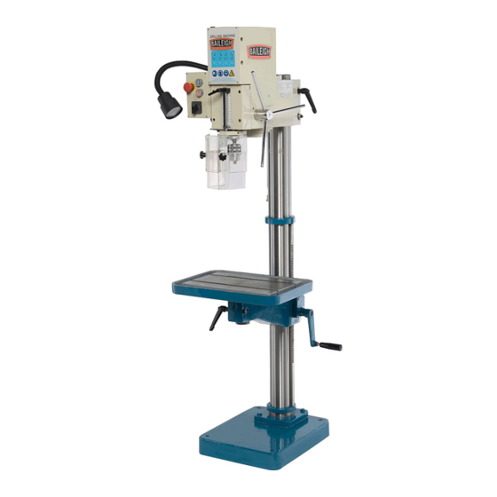
GEAR DRIVE DRILL PRESS
MODEL: DP-1000G
Baileigh Industrial, Inc.
P.O. Box 531
Manitowoc, WI 54221-0531
Phone: 920.684.4990
Fax: 920.684.3944
sales@baileighindustrial.com
REPRODUCTION OF THIS MANUAL IN ANY FORM WITHOUT WRITTEN APPROVAL OF BAILEIGH INDUSTRIAL, INC.
IS PROHIBITED. Baileigh Industrial, Inc. does not assume and hereby disclaims any liability for any damage or loss
caused by an omission or error in this Operator's Manual, resulting from accident, negligence, or other occurrence.
Rev. 05/2015
© 2015 Baileigh Industrial, Inc.
Advertisement
Table of Contents

Related Manuals for Baileigh DP-1000G


Summary of Contents for Baileigh DP-1000G
- Page 1 REPRODUCTION OF THIS MANUAL IN ANY FORM WITHOUT WRITTEN APPROVAL OF BAILEIGH INDUSTRIAL, INC. IS PROHIBITED. Baileigh Industrial, Inc. does not assume and hereby disclaims any liability for any damage or loss caused by an omission or error in this Operator’s Manual, resulting from accident, negligence, or other occurrence.
-
Page 2: Table Of Contents
Table of Contents THANK YOU & WARRANTY ..................1 INTRODUCTION ......................3 GENERAL NOTES ......................3 SAFETY INSTRUCTIONS ....................4 SAFETY PRECAUTIONS ....................6 MACHINE DESCRIPTION ....................7 TECHNICAL SPECIFICATIONS ..................8 TECHNICAL SUPPORT ....................8 UNPACKING AND CHECKING CONTENTS ..............9 Cleaning ........................ - Page 3 ELECTRIC BOX DIAGRAM ..................39 Electrical Box Parts List ..................... 40 ELECTRICAL SCHEMATIC ..................41...
-
Page 4: Thank You & Warranty
THANK YOU & WARRANTY Thank you for your purchase of a machine from Baileigh Industrial. We hope that you find it productive and useful to you for a long time to come. Inspection & Acceptance. Buyer shall inspect all Goods within ten (10) days after receipt thereof. Buyer’s payment shall constitute final acceptance of the Goods and shall act as a waiver of the Buyer’s rights to inspect or... - Page 5 Baileigh Industrial makes every effort to ensure that our posted specifications, images, pricing and product availability are as correct and timely as possible. We apologize for any discrepancies that may occur. Baileigh Industrial reserves the right to make any and all changes deemed necessary in the course of business including but not limited to pricing, product specifications, quantities, and product availability.
-
Page 6: Introduction
After receiving your equipment remove the protective container. Do a complete visual inspection, and if damage is noted, photograph it for insurance claims and contact your carrier at once, requesting inspection. Also contact Baileigh Industrial and inform them of the unexpected occurrence. Temporarily suspend installation. -
Page 7: Safety Instructions
IMPORTANT PLEASE READ THIS OPERATORS MANUAL CAREFULLY It contains important safety information, instructions, and necessary operating procedures. The continual observance of these procedures will help increase your production and extend the life of the equipment. SAFETY INSTRUCTIONS LEARN TO RECOGNIZE SAFETY INFORMATION This is the safety alert symbol. - Page 8 SAVE THESE INSTRUCTIONS. Refer to them often and use them to instruct others. PROTECT EYES Wear safety glasses or suitable eye protection when working on or around machinery. PROTECT AGAINST NOISE Prolonged exposure to loud noise can cause impairment or loss of hearing.
-
Page 9: Safety Precautions
SAFETY PRECAUTIONS Metal working can be dangerous if safe and proper operating procedures are not followed. As with all machinery, there are certain hazards involved with the operation of the product. Using the machine with respect and caution will considerably lessen the possibility of personal injury. However, if normal safety precautions are overlooked or ignored, personal injury to the operator may result. -
Page 10: Machine Description
23. Keep visitors a safe distance from the work area. MACHINE DESCRIPTION The Baileigh DP-1000G is a very economical gear head drill press that can run in any fabrication or machine shop using only 110 volts of power. It can drill through mild steel with up to a 1"... -
Page 11: Technical Specifications
TECHNICAL SPECIFICATIONS Drill Capacity 1” (25.4mm) Tapping Capacity .625” (15.875mm) Spindle Speed 125, 420, 535, or 1740 rpm Spindle Taper MT 3 Spindle Travel 5.3” (135mm) Tables Dimensions (L x W) 19.75 x 13.75 (501 x 350mm) Base Dimensions (L x W) 15.5 x 19.5 (393 x 495mm) Motor 1.5hp (1.12kw) -
Page 12: Unpacking And Checking Contents
UNPACKING AND CHECKING CONTENTS Your Baileigh machine is shipped complete in one crate. Separate all parts from the packing material and check each item carefully. Make certain all items are accounted for before discarding any packing material. WARNING: SUFFOCATION HAZARD! Immediately discard any plastic bags and packing materials to eliminate choking and suffocation hazards to children and animals. -
Page 13: Transporting And Lifting
TRANSPORTING AND LIFTING IMPORTANT: Lifting and carrying operations should be carried out by skilled workers, such as a truck operator, crane operator, etc. If a crane is used to lift the machine, attach the lifting chain carefully, making sure the machine is well balanced. Follow these guidelines when lifting with truck or trolley: •... -
Page 14: Installation
INSTALLATION IMPORTANT: Consider the following when looking for a suitable location to place the machine: • Overall weight of the machine. • Weight of material being processed. • Sizes of material to be processed through the machine. • Space needed for auxiliary stands, work tables, or other machinery. •... -
Page 15: Overall Dimensions
OVERALL DIMENSIONS... -
Page 16: Getting To Know Your Machine
GETTING TO KNOW YOUR MACHINE... - Page 17 Item Description Function Base Support the drill press Loosen to allow the table to rotate on its center axis. Table Rotation Lock NEVER OPERATE THE MACHINE WHEN UNLOCKED. Work Table Work surface with T-slots Chuck Holds various tools for drilling and tapping Adjustable guard to cover the chuck and restrict Drill Guard access during operation...
-
Page 18: The Drill Head
The Drill Head The drill head attaches to the upper column. It houses the motor, spindle, and speed controls. Attached to it is the electrical enclosure, the protective guard, the work light. The drill head can be lowered, raised, and rotated on the column as needed. -
Page 19: Electrical
ELECTRICAL CAUTION: HAVE ELECTRICAL UTILITIES CONNECTED TO MACHINE BY A CERTIFIED ELECTRICIAN! Check if the available power supply is the same as listed on the machine nameplate. WARNING: Make sure the grounding wire (green) is properly connected to avoid electric shock. DO NOT switch the position of the green grounding wire if any electrical plug wires are switched during hookup. - Page 20 • Improper connection of the equipment-grounding conductor can result in risk of electric shock. The conductor with insulation having an outer surface that is green with or without yellow stripes is the equipment-grounding conductor. If repair or replacement of the electric cord or plug is necessary, do not connect the equipment-grounding conductor to a live terminal.
-
Page 21: Operation
OPERATION CAUTION: Always wear proper eye protection with side shields. Restrain and contain long hair, loose or baggy clothing and remove jewelry to prevent entanglement. Safety guard must be properly positioned. 1. Load and secure the piece part to the table. 2. -
Page 22: Material Selection
Note: In general, use low speeds for tapping. By tapping at high RPM there is a danger of damage to the piece part or the tooling. While tapping, the tool can be backed out at any time by stopping the spindle rotation and changing the selector switch (G). 13. -
Page 23: Lubrication And Maintenance
LUBRICATION AND MAINTENANCE WARNING: Make sure the electrical disconnect is OFF before working on the machine. Maintenance should be performed on a regular basis by qualified personnel. Always follow proper safety precautions when working on or around any machinery. Daily Maintenance •... -
Page 24: Drill Head Diagram
DRILL HEAD DIAGRAM... -
Page 25: Drill Head Parts List
Drill Head Parts List Item Part No. Description Notes 2X08700 Spindle Housing 2X08404 Gearbox 2X08719 Spindle Sleeve 2X08740-5 Feed Shaft Complete 2X08720 Worm Gear Unit 2X08702 Front Cover 4U08705 Electric Box Cover 3R00014 Locking Lever 3S02556 Screw M12x120 3S02558 Screw M12x130 3M09122 Locking Nut... -
Page 26: Gearbox Diagram
GEARBOX DIAGRAM... -
Page 27: Gearbox Parts List
Gearbox Parts List Item Part No. Description Notes Rotor shaft 2X08404-2 2nd Shaft complete 2X08404-3 3rd Shaft complete 2X08422 Gear box complete 4B00174 Ring 4B00173 Ring 2X08536 Gear selector arm 4RS0653-1 Gear lever 4C02921 Gear 3T04028 Steel ball 4T04168 Shift pin... -
Page 28: Rotor Shaft Diagram
ROTOR SHAFT DIAGRAM... -
Page 29: Rotor Shaft Parts List
Rotor Shaft Parts List Item Part. No. Description Notes 4B00137 Washer 3L11003 Ball bearing 6203 2H07969 Gear 15-1, 5 2D17014 Spacing sleeve 17x14 2H07972 Gear 39-1, 5 2D17002 Spacing sleeve 17x2 3L11003 Ball bearing 6203 4B00137 Washer 3K00184 5x5x14 3K00187 5x5x20 2X08405 Rotor Shaft... -
Page 30: 2Nd Shaft Diagram
2nd SHAFT DIAGRAM... -
Page 31: 2Nd Shaft Parts List
2nd Shaft Parts List Item Part No. Description Notes 4B00138 Washer C-138 3L11003 Ball bearing 6203 2D00009 Spacing sleeve 17x3, 5 2H07971 Gear 32-2 2D17038 Spacing sleeve 17x38 2H07970 Gear 15-2 2D17005 Spacing sleeve 17x5 2A04871 2nd Shaft C-4871 3K00187 5x5x20 2T06615 C-6615... -
Page 32: 3Rd Shaft Diagram
3rd SHAFT DIAGRAM... -
Page 33: 3Rd Shaft Parts List
3rd Shaft Parts List Item Part No. Description Notes 4B00138 Cover C-138 3L16002 Ball bearing 6302 3015002 Spacing sleeve 15x2 3C01117 Circlip SgA 15 2X08413 Gear complete 32-2 2T04254 Clutch C 4254 2X08411 Gear complete 49-2 2000006 Spacing sleeve 17x31, 5 3L11003 Ball bearing 6203... -
Page 34: Column Diagram
COLUMN DIAGRAM... -
Page 35: Column Parts List
Column Parts List Item Part No. Description Notes 2W07802 Base plate L=1500 4X08300 Column 2X08723 Table arm complete 2WS1231 Table 2X08445 Rack 2T07146 2Y08723 Table arm 2X08720-1 Worm gear complete 2RS1182 Crank handle 3RO1106 Handle 2IS1203 Worm shaft 2D20008 2D20008 2HS1201 Gear 2AS1202... -
Page 36: Worm Gear Box Complete Diagram
WORM GEAR BOX COMPLETE DIAGRAM... -
Page 37: Worm Gear Box Complete Parts List
Worm Gear Box Complete Parts List Item Part No. Description Notes 2X08720 Worm gear box Complete 2N08720 Worm gear box 2AS1202 Shaft 2HS1201 Gear 2D20008 Spacer 20x8 2IS1203 Worm shaft 3L00021 Washer 2RS1182 Crank 3RO1106 Handle 3S04444 Screw SK6SS 8x8... -
Page 38: Feedshaft Diagram
FEEDSHAFT DIAGRAM... -
Page 39: Feed Shaft Parts List
Feed Shaft Parts List Item Part No. Description Notes 4T08715 Spring housing 4C03026 Spring 2108708 Feed shaft 4S04211 Screw 2E08722 Feed lever 3R02003 Handle ball... -
Page 40: Spindle Sleeve Diagram
SPINDLE SLEEVE DIAGRAM... -
Page 41: Spindle Sleeve Parts List
Spindle Sleeve Parts List Item Part No. Description Notes 3M06005 4B00155 Locking washer 3L11005 Ball bearing 6205 2G08709 Spindle sleeve 2I08420 Rack 4B03769 Washer 3L51006 Taper roller bearing 30206 2TS1106 Roller bearing cover 2T08386 2A08418-1 Spindle 2T08593 Spacing sleeve 3B06003 Washer 4T08547 Stop... - Page 42 ELECTRIC BOX DIAGRAM...
- Page 43 Electrical Box Parts List Item Part No. Description Notes 4U08705 Electric box cover 2L08712 Rail anchor 3E10604 Motor Protector 380/50 2E08713 Electric box distance tube 4L08706 Anchor plate 4L08711-3 Electric box plate 3E16227 Emergency stop 3T18003 Rubber molding 15x8 3E06016 Pole reverser 3E19088 1816...
- Page 44 ELECTRICAL SCHEMATIC...
- Page 45 Item Description Specification Motor Contactor Thermal Overload Transformer Emergency Stop Button Push Button (Start) Push Button (Stop) Work Lamp Capacitor Capacitor Rotation Selector Switch...
- Page 46 NOTES...
- Page 47 NOTES...
- Page 48 BAILEIGH INDUSTRIAL, INC. 1625 D , WI 54220 UFEK RIVE ANITOWOC : 920. 684. 4990 F : 920. 684. 3944 HONE www.baileigh.com BAILEIGH INDUSTRIAL LTD. U WIFT OINT WIFT ALLEY NDUSTRIAL STATE UGBY , CV21 1QH U IDLANDS NITED INGDOM...
Need help?
Do you have a question about the DP-1000G and is the answer not in the manual?
Questions and answers