Table of Contents
Advertisement
Quick Links
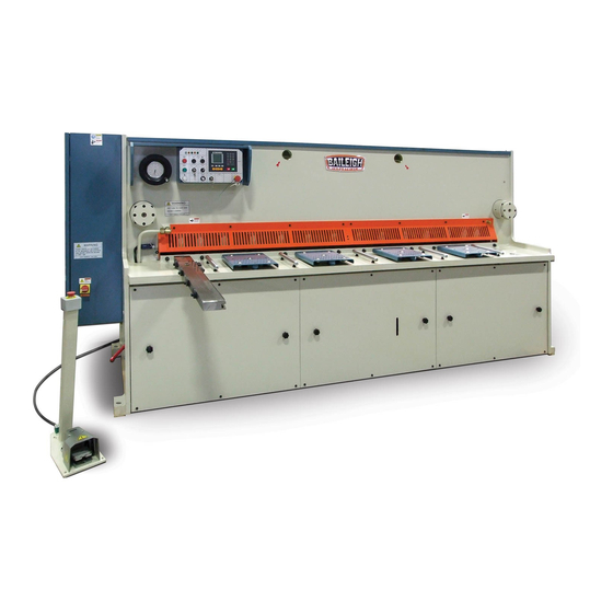
OPERATOR'S MANUAL
HYDRAULIC SHEAR
MODEL: SH-70250-HD
Baileigh Industrial Holdings LLC
P.O. Box 531
Manitowoc, WI 54221-0531
Phone: 920.684.4990
Fax: 920.684.3944
sales@baileigh.com
REPRODUCTION OF THIS MANUAL IN ANY FORM WITHOUT WRITTEN APPROVAL OF BAILEIGH INDUSTRIAL
HOLDINGS LLC IS PROHIBITED. Baileigh Industrial Holdings LLC, Inc. does not assume and hereby disclaims any
liability for any damage or loss caused by an omission or error in this Operator's Manual, resulting from accident,
negligence, or other occurrence.
Rev. 09/2019
© 2019 Baileigh Industrial Holdings LLC
Advertisement
Table of Contents

Subscribe to Our Youtube Channel
Related Manuals for Baileigh SH-70250-HD


Summary of Contents for Baileigh SH-70250-HD
- Page 1 REPRODUCTION OF THIS MANUAL IN ANY FORM WITHOUT WRITTEN APPROVAL OF BAILEIGH INDUSTRIAL HOLDINGS LLC IS PROHIBITED. Baileigh Industrial Holdings LLC, Inc. does not assume and hereby disclaims any liability for any damage or loss caused by an omission or error in this Operator’s Manual, resulting from accident, negligence, or other occurrence.
-
Page 2: Table Of Contents
Table of Contents LUBRICATION AND MAINTENANCE ................1 Machine Lubrication ....................1 Blade Changing and Grinding..................1 Hydraulic System ......................2 Changing Hydraulic Oil ....................2 Hydraulic Pressure Filling the Accumulator ..............4 HYDRAULIC SCHEMATIC ..................... 5 Hydraulic Parts List ...................... 6 List of Hydraulic Wear Parts .................. -
Page 3: Lubrication And Maintenance
LUBRICATION AND MAINTENANCE WARNING: Make sure the electrical disconnect is OFF before working on the machine. Maintenance should be performed on a regular basis by qualified personnel. Always follow proper safety precautions when working on or around any machinery. • Check daily for any unsafe conditions and fix immediately. •... -
Page 4: Hydraulic System
• The schedule recommended above is only to be used for the shears put into normal operation. If the cutting edges of blade are arranged for grinding following the schedule, the removal quantity of blade would be minimum, and its lifetime be maximum possible. •... - Page 5 4. Remove the top cover and clean the hydraulic tank and re-install the top cover. 5. Use hydraulic oil #68 SHELL BRAND or an equivalent with similar specifications to fill the hydraulic tank until it reaches the midpoint on the sight gauge. 6.
-
Page 6: Hydraulic Pressure Filling The Accumulator
Hydraulic Pressure Filling the Accumulator NOTICE: This is not a common function. The accumulator has been charged from the factory and will not require charging unless someone has tempered with or inadvertently actuated the accumulator hydraulic circuit ball valve. The accumulator will only require hydraulic pressure filling if the hydraulic pressure gauge is below 8MPa AND the shearing ram will not lift and hold at the full up position. -
Page 7: Hydraulic Schematic
HYDRAULIC SCHEMATIC... -
Page 8: Hydraulic Parts List
Hydraulic Parts List Item Code Name Qty. Remarks Left Cylinder Clamping Cylinder Two Way Valve Throttle Valve QUQ2-20x1.0 Air Filter TS-5 Fluid Level WF-12x100 Oil Filter DGMC-5-PT-GW-41 Pressure Valve VICKERS DVQ25-22FRAR-02 Oil Pump Y132M-4 Motor 7.5kW 4WE10H73-3X/EG24N9K4A12 Solenoid Valve REXROTH SO5A-R3/I4 Balance Valve GCT-02... -
Page 9: List Of Hydraulic Wear Parts
List of Hydraulic Wear Parts No. Name Specification Qty. Position Remarks Dustproof Seal DH (LBI) 55x63x5x6.3 Left Cylinder Guide Seal RYT15x2.5x173 Left Cylinder Rod Seal T605-4615600 Left Cylinder HALLITE "O"-Ring G120 Left Cylinder "O"-Ring Left Cylinder Piston Seal GSP 125x110x6.6 Left Cylinder REDUX Guide Seal... -
Page 10: Left Hydraulic Cylinder Diagram
LEFT HYDRAULIC CYLINDER DIAGRAM... -
Page 11: Right Hydraulic Cylinder Diagram
RIGHT HYDRAULIC CYLINDER DIAGRAM... -
Page 12: Clamping Hydraulic Cylinder Diagram
CLAMPING HYDRAULIC CYLINDER DIAGRAM... -
Page 13: Electrical Component Locations
ELECTRICAL COMPONENT LOCATIONS... -
Page 15: Electrical Schematic
ELECTRICAL SCHEMATIC... -
Page 24: Electrical Components List
Electrical Components List Code Type Name Specifications Qty. V2+KCF1PZ Power switch GG45-D40-3P Circuit breaker 40A, 3P LC1-D32B7C AC contactor AC24V, 50-60Hz LAD-N31C Auxiliary contact LRD-32C Thermo-relay 23-32A JBK5-630 Transformer GG45-D6-2P Circuit breaker 6A, 2P GG45-D10-1P Circuit breaker 10A, 1P GG45-D3-1P Circuit breaker 3A, 1P GG45-D6-1P... - Page 25 YSD6000S Numerical control system PAXD Counter RV30YN20SB203 Potentiometer XB2-BVB1C Power pilot lamp ZB2-BS54C Push button ZB2-BZ102C Push button XB 5-AA42C Push button ZB2-BW33C Push button ZB2-BWB31C Push button XB5-AA21C Push button ZB2-BG2C Push button ZB2-BZ101C Push button ZB2-BD2C Push button ZB2-BE102C Push button XCK-M110...
- Page 26 NOTES...
- Page 27 NOTES...
- Page 28 BAILEIGH INDUSTRIAL HOLDINGS LLC 1625 D , WI 54220 UFEK RIVE ANITOWOC : 920. 684. 4990 F : 920. 684. 3944 HONE www.baileigh.com BAILEIGH INDUSTRIAL HOLDINGS LTD. U WIFT OINT WIFT ALLEY NDUSTRIAL STATE UGBY , CV21 1QH U IDLANDS...
Need help?
Do you have a question about the SH-70250-HD and is the answer not in the manual?
Questions and answers