Table of Contents
Advertisement
Quick Links
OPERATOR'S
MANUAL
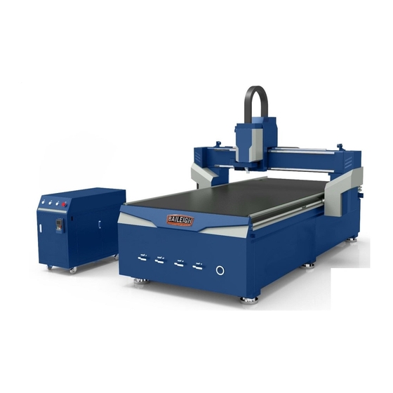
ROUTER TABLE
MODEL: WR-84V-ATC
Baileigh Industrial, Inc.
P.O. Box 531
Manitowoc, WI 54221-0531
Phone: 920.684.4990
Fax: 920.684.3944
sales@baileigh.com
REPRODUCTION OF THIS MANUAL IN ANY FORM WITHOUT WRITTEN APPROVAL OF BAILEIGH INDUSTRIAL, INC.
IS PROHIBITED. Baileigh Industrial, Inc. does not assume and hereby disclaims any liability for any damage or loss
caused by an omission or error in this Operator's Manual, resulting from accident, negligence, or other occurrence.
Rev. 08/2018
© 2018 Baileigh Industrial, Inc.
Advertisement
Table of Contents

Subscribe to Our Youtube Channel
Related Manuals for Baileigh WR-84V-ATC


Summary of Contents for Baileigh WR-84V-ATC
- Page 1 REPRODUCTION OF THIS MANUAL IN ANY FORM WITHOUT WRITTEN APPROVAL OF BAILEIGH INDUSTRIAL, INC. IS PROHIBITED. Baileigh Industrial, Inc. does not assume and hereby disclaims any liability for any damage or loss caused by an omission or error in this Operator’s Manual, resulting from accident, negligence, or other occurrence.
-
Page 2: Table Of Contents
Table of Contents THANK YOU & WARRANTY ..................1 INTRODUCTION ......................3 GENERAL NOTES ......................3 SAFETY INSTRUCTIONS ....................4 SAFETY PRECAUTIONS ....................7 Dear Valued Customer: ....................7 Noise Emission ......................10 Combustion Hazard ....................10 Combustion and Explosion Conditions ..............10 SPECIFICATIONS ...................... -
Page 3: Thank You & Warranty
THANK YOU & WARRANTY Thank you for your purchase of a machine from Baileigh Industrial. We hope that you find it productive and useful to you for a long time to come. Inspection & Acceptance. Buyer shall inspect all Goods within ten (10) days after receipt thereof. Buyer’s payment shall constitute final acceptance of the Goods and shall act as a waiver of the Buyer’s rights to inspect or... - Page 4 Baileigh Industrial makes every effort to ensure that our posted specifications, images, pricing and product availability are as correct and timely as possible. We apologize for any discrepancies that may occur. Baileigh Industrial reserves the right to make any and all changes deemed necessary in the course of business including but not limited to pricing, product specifications, quantities, and product availability.
-
Page 5: Introduction
After receiving your equipment remove the protective container. Do a complete visual inspection, and if damage is noted, photograph it for insurance claims and contact your carrier at once, requesting inspection. Also contact Baileigh Industrial and inform them of the unexpected occurrence. Temporarily suspend installation. -
Page 6: Safety Instructions
IMPORTANT PLEASE READ THIS OPERATORS MANUAL CAREFULLY It contains important safety information, instructions, and necessary operating procedures. The continual observance of these procedures will help increase your production and extend the life of the equipment. SAFETY INSTRUCTIONS LEARN TO RECOGNIZE SAFETY INFORMATION This is the safety alert symbol. - Page 7 SAVE THESE INSTRUCTIONS. Refer to them often and use them to instruct others. PROTECT EYES Wear safety glasses or suitable eye protection when working on or around machinery. PROTECT AGAINST NOISE Prolonged exposure to loud noise can cause impairment or loss of hearing.
- Page 8 CUTTING HAZARD Keep hands and fingers away from the rotating shaper cutters. These rotating cutters can be extremely dangerous if you do not follow proper safety procedures. NEVER place hands directly over or in front of the cutter. Keep hand at least 6” (150mm) from the shaper cutter while operating.
-
Page 9: Safety Precautions
• All Baileigh woodworking machines should be used only for their intended use. • Baileigh does not recommend or endorse making any modifications or alterations to a Baileigh machine. Modifications or alterations to a machine may pose a substantial risk of injury to the operator or others and may do substantial damage to the machine. - Page 10 7. Do not force tool. Your machine will do a better and safer job if used as intended. DO NOT use inappropriate attachments in an attempt to exceed the machines rated capacity. 8. Use the right tool for the job. DO NOT attempt to force a small tool or attachment to do the work of a large industrial tool.
- Page 11 23. Know the location of the ON - OFF switch and the “E” - STOP button. 24. DO NOT bypass or defeat any safety interlock systems. 25. Keep visitors a safe distance from the work area. 26. Machines can eject piece parts towards the operator. Know and avoid the conditions which cause the piece part to kickback.
-
Page 12: Noise Emission
Noise Emission Given that there exists a relationship between noise level and exposure times, it is not precise enough to determine the need for supplementary precautions. The factors affecting the true level of exposure to operators are clearly the amount of time exposed, the characteristics of the working environment sources of dust and noise, etc. -
Page 13: Specifications
SPECIFICATIONS Power 220V, 3Ph, 60Hz, 60A* Horsepower (Router) 10hp (7.45kw) air cooling spindle (ATC) Table Dimensions (L x W x H) 132” x 83” x 70” (3353 x 2109 x 1778mm) 50.5” x 96.5” x 6.7” (1283 x 2450 x 170mm) Actual Working Area Table Vacuum Table... -
Page 14: Technical Support
(other than die sets and blades). For specific application needs or future machine purchases contact the Sales Department at: sales@baileigh.com, Phone: 920.684.4990, or Fax: 920.684.3944. Note: The specifications and dimensions presented here are subject to change without prior notice due to improvements of our products. -
Page 15: Unpacking And Checking Contents
UNPACKING AND CHECKING CONTENTS Your Baileigh machine is shipped complete. Separate all parts from the packing material and check each item carefully. Make certain all items are accounted for before discarding any packing material. WARNING: SUFFOCATION HAZARD! Immediately discard any plastic bags and packing materials to eliminate choking and suffocation hazards to children and animals. -
Page 16: Transporting And Lifting
TRANSPORTING AND LIFTING CAUTION: Lifting and carrying operations should be carried out by skilled workers, such as a truck operator, crane operator, etc. If a crane is used to lift the machine, attach the lifting chain carefully, making sure the machine is well balanced. Choose a location that will keep the machine free from vibration and dust from other machinery. -
Page 17: Getting To Know Your Machine
• Remove scrap and waste materials, make sure the work area is free from obstructions. • It is important to maintain free area around the machine, which is required for the working place. If any long material is machined, it is necessary to have a sufficient room in front of the machine as well behind it in the places of material input and output. -
Page 18: Assembly And Set Up
• Electrical Control Cabinet. The electrical control cabinet is a separate console that may be positioned as needed by the operator within the length of the connecting cables. The operator must however, position the cabinet to provide quick access to the emergency stop if needed, and make sure it does not interfere with the operation of the gantry, or loading and unloading of material. -
Page 19: Preparing The Vacuum Pump
Preparing the Vacuum Pump 1. Verify that the label on the pump indicates the correct power requirements, 220V, 3ph, 20A. Plug 2. Place the vacuum pump at the rear of the table within reach of the main vacuum port. Leave a minimum of 6” (153mm) of open space on all side of the pump for air flow and service access. - Page 20 5. Have an electrician route and connect a power cord (customer supplied) from the vacuum pump to the console electrical cabinet terminal strip. 6. Connect the L1, L2, and L3 wires to the terminal block using the Delta (Δ) wiring on the motor as shown.
-
Page 21: Air Connection And Settings
Air Connection and Settings 1. Route the air line into the filter side (A) of the filter / regulator assembly. The air supply (customer supplied) should be 9-10CFM @ 85psi. 2. Push the air line into the quick connect and verify that it is locked into the coupler. -
Page 22: Electrical
ELECTRICAL WARNING: Baileigh Industrial is not responsible for any damage caused by wiring up to an alternative 3-phase power source other than direct 3-phase. If you are using an alternate power source, consult a certified electrician or contact Baileigh Industrial prior to energizing the machine. -
Page 23: Power Cord Connection
WARNING: In all cases, make certain the receptacle in question is properly grounded. If you are not sure, have a qualified electrician check the receptacle • Improper connection of the equipment-grounding conductor can result in risk of electric shock. The conductor with insulation having an outer surface that is green with or without yellow stripes is the equipment-grounding conductor. -
Page 24: Operation
OPERATION CAUTION: Always wear proper eye protection with side shields, safety footwear. Start by reading and familiarizing yourself with the Weihong NK105G2/G3 Controller Operation Manual following the NK105G3 specific information. This manual will go through all of the settings, keys, and functions of the controller. The instructions within this manual will only cover basic operation of a general program. - Page 25 The outside edge of the System button will illuminate in Red when power is connected to the control cabinet and the table is Not powered On. When the System Button (Off Button) table is powered On, the light will be off. When the machine is in operation, pressing the System button will shut down the machine operation.
-
Page 26: Hand Held Controls
Hand Held Controls With the use of single-key or combination keys, all the operations can be realized. The single-key functions are primarily based upon the larger symbol and the center of each key. These commands will change for example when entering numbers. For example: The Y+ key will automatically be the digit 8 when the cursor on screen is in a field that has a number value that can be changed. - Page 27 Single Key Function Table Key Icon Key Name Function Start key; breakpoint resume with the help of the Start auxiliary key Pause Pause during machining Stop Stop machining Spindle ON/OFF Start or stop of spindle under manual mode Entering menu page; entering image update page Menu at the time of system start-up;...
- Page 28 Positive movement of Z axis; input of number 9 Negative movement of Z axis; input of number 3; measurement after tool change with the help of the auxiliary key Switches between jog speed and rapid jog speed in Speed Change jog mode;...
- Page 29 Function Information of Combination Key The usage of the combination key: press the auxiliary key, and then the second; release the two keys after the corresponding function is called. Combination Key Function Table Key icon Function Breakpoint resume entering help page of combination key X clearing Y clearing Increase of spindle gear...
-
Page 30: Start Up
Start Up 1. Verify that the table surface is clear for the spindle to move. 2. Verify that both the E-Stop buttons are released. 3. Press the Power button and allow the system to boot up. 4. When the message is displayed on the hand-held control to “Back to REF point”, press OK. -
Page 31: Loading A Program
4. Press the (Z=0) key to set the Z coordinate work position. 5. If the current XY location is not the desired starting point, use the X and Y coordinated keys, to move the spindle to the desired starting location. 6. - Page 32 3. Use the up or down arrows on the (navigation) key to select the USB File if desired. Press on the desired file source. Local File used for this example. √ T1.nc T2.nc T3.nc ①Ld②De③Copy 4. When the files are listed, use the up or down arrows on the navigation key to select the file that you want to load into the controller.
- Page 33 10. Press the (ESC) key to return to the main operating screen. 11. Verify that the spindle and the table are clear and safe for operation. Press the (Start) key to start the machining operation. 999.000 999.000 -99.000 Slow F:3600 100% Note: The coordinates for the X, Y, and Z axis will be the values that the spindle is at and will be changing as the head moves to complete the program.
-
Page 34: Setting The Tool Length
SETTING THE TOOL LENGTH One of the first things that will need to be done is loading the cutting tool into the tool holders. Each tool must then be placed into the tool magazine in the exact location as defined in the programming software. -
Page 35: Manually Changing Tool Holders
5. Scroll to and load the file “T1.NC”. This will be the file number for tool number 1 in which you are going to measure. 6. When the file is loaded, press the (Start) key to execute the program to change to the desired tool. - Page 36 3. With the table powered On, Press the “Menu” key, scroll down to the “Operation” option and press OK. 4. Scroll up to the “Tool Change Parameter” and press OK. 5. Scroll to “Current ToolNo.” and press OK. The tool number shown must match the empty magazine location.
-
Page 37: Menu Tree
14. The bit will touch the sensor, (typically twice and may appear as a quick bounce), and then lift approximately 1mm above the touch pad. 15. When completed, tool number 3 has been measured and that Z coordinate will have been recorded within the systems memory. -
Page 38: Attaching The Workpiece
Book 2 shows the tables of the options that are listed in the full system menu. While most options are available and active, some are not. Those options under the Mfg Parameter require a password to enter to help prevent damage to the material and machine. When a menu item is highlighted, use the OK key to enter the next level, or accept any changes. -
Page 39: Sacrificial Board
Vacuum Considerations • Regularly clean the vacuum system air filters and passages to ensure enough vacuum force. • Seal as much of the surface between the table and the workpiece and possible to limit vacuum leakage. • When using spoil board (typical and recommended) such as MDF or similar, use a fly cutter to machine both surfaces to remove just enough material to open the pours of the material to allow the vacuum to suck through the material. - Page 40 Precautions regarding sacrificial boards The sacrificial board will become porous when the melamine has been cut through, and will absorb moisture. As moisture is absorbed the dimensions of the board will change. In general, this will not be a problem as the changes from day to day are typically very small. Also, the changes will in general be over the complete board.
- Page 41 8. Move the router head in the X+ direction so that it is approximately at the end of the sacrificial board. 9. Move the sacrificial board so that it lines up with the point of the router bit. 10. Place tape on the bed of the machine at the edge of the sacrificial board. 11.
-
Page 42: Router Bit Installation And Removal
ROUTER BIT INSTALLATION AND REMOVAL Spindle Nut Collet Note: Collets & spindle collet hole must be cleaned regularly. Ensure that the slots in the collets are free of sawdust, as sawdust build up will keep the collet from compressing. If the collet or spindle holes are not clean, the router bit may not run true and this will affect the performance of your machine. -
Page 43: Router Bits
Router Bits Types of router bits. There are five basic types of router bits: straight, up shear, down shear, combination (also called compression), and form tools (round over, ogee, etc.). 1. Straight Router Bits. These are the standard router bits that are commonly used with handheld routers and are readily available at most home centers. -
Page 44: Automatic Oiler
AUTOMATIC OILER The router table has an automatic lubricating system mounted on the back side of the left end of the gantry. The oiler can be set for both the time intervals between oiling cycles, and how long the pump runs during an oiling cycle. -
Page 45: Air Mister
• When the display shows “ERP”, it means low system pressure. Check for pipe/tube damage or leaks, or the lubrication cycle time is too short to develop a pressure reading. • When the display shows “ERS”, it means that the system is running overtime. AIR MISTER The air mist system may be used to spray air at the cutting area or coolant using a siphon system where the air draws the coolant into the block and then sprays the air coolant mixture at... -
Page 46: Lubrication And Maintenance
LUBRICATION AND MAINTENANCE WARNING: Make sure the electrical disconnect is OFF before working on the machine. Maintenance should be performed on a regular basis by qualified personnel. Always follow proper safety precautions when working on or around any machinery. Daily Maintenance •... -
Page 47: Air Pressure System Maintenance
• Clean the cutters. • Generally inspect the machine for damage and loose or worn parts. • Check the dust extraction system for blockages and any large scrap that could cause blockages. • Check the screen on the inlet of the vacuum pump for debris. Monthly Maintenance •... -
Page 49: Parts List
Parts List Part Name Model No. NK105 DSP Controller 1 set Delta Inverter 11KW/220V 1 pc Delta Motor with Brake 750W 1 pc Delta Motor 750W 3 pc Relay 8 set Switch Power D-120C 2 pc Phase Sequence XJ-3 1 pc A.C. - Page 50 Solenoid Valve 4 pc Tool Sensor 1 pc Tool Box 1 pc Tool Holder ISO30 6 pc Tool Support 6 pc Air Cylinder for tool 1 pc Oil-Water Separator 1 pc Air Cylinder for Dust Collection 2 pc Unloading Wrench 1 pc Tool Collet 3.175...
-
Page 51: Electrical Schematic
ELECTRICAL SCHEMATIC... -
Page 54: Software Information
SOFTWARE INFORMATION Each new cutting table comes with one license of the latest version of BobCAD CAM Express software and Services provided by BobCAD-CAM. Contact a representative from BobCAD-CAM to get started with BobCAD-CAM. The service representative will help to get you directed to the download links and the license activated. Whether drawing squares or squirrels, flanges or flowers, BobCAD-CAM will help to bring out your drafting artistry skills. - Page 55 Use the information below to ensure you are working with a BobCAD-CAM supported and optimized system. Use the following link to view the most up to date system requirements. http://bobcad.com/support/system-requirements/?source=webinars_footer BobCAD-CAM is supported to run on the following Operating Systems: •...
- Page 56 NOTES BAILEIGH INDUSTRIAL, INC. 1625 D , WI 54220 UFEK RIVE ANITOWOC : 920. 684. 4990 F : 920. 684. 3944 HONE BAILEIGH BAILEIGH INDUSTRIAL LTD. U ULLWOOD LOSE WIFT ALLEY NDUSTRIAL STATE UGBY , CV21 1QH U IDLANDS NITED...
Need help?
Do you have a question about the WR-84V-ATC and is the answer not in the manual?
Questions and answers