Table of Contents
Advertisement
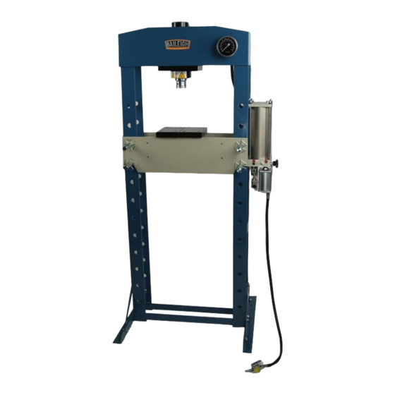
OPERATOR'S MANUAL
30 TON SHOP PRESS
MODEL: HSP-30A
Baileigh Industrial Holdings LLC
P.O. Box 531
Manitowoc, WI 54221-0531
Phone: 920.684.4990
Fax: 920.684.3944
sales@baileigh.com
REPRODUCTION OF THIS MANUAL IN ANY FORM WITHOUT WRITTEN APPROVAL OF BAILEIGH INDUSTRIAL
HOLDINGS LLC IS PROHIBITED. Baileigh Industrial Holdings LLC, Inc. does not assume and hereby disclaims any
liability for any damage or loss caused by an omission or error in this Operator's Manual, resulting from accident,
negligence, or other occurrence.
Rev. 05/2020
© 2020 Baileigh Industrial Holdings LLC
Advertisement
Table of Contents

Related Manuals for Baileigh HSP-30A


Summary of Contents for Baileigh HSP-30A
- Page 1 REPRODUCTION OF THIS MANUAL IN ANY FORM WITHOUT WRITTEN APPROVAL OF BAILEIGH INDUSTRIAL HOLDINGS LLC IS PROHIBITED. Baileigh Industrial Holdings LLC, Inc. does not assume and hereby disclaims any liability for any damage or loss caused by an omission or error in this Operator’s Manual, resulting from accident, negligence, or other occurrence.
-
Page 2: Table Of Contents
Table of Contents THANK YOU & WARRANTY ..................1 INTRODUCTION ......................3 GENERAL NOTES ......................3 SAFETY INSTRUCTIONS ....................4 SAFETY PRECAUTIONS ....................6 Dear Valued Customer: ....................6 MACHINE SAFETY LABELS ..................8 TECHNICAL SPECIFICATIONS ..................9 TECHNICAL SUPPORT ....................9 UNPACKING AND CHECKING CONTENTS .............. -
Page 3: Thank You & Warranty
THANK YOU & WARRANTY Thank you for your purchase of a machine from Baileigh Industrial Holdings LLC. We hope that you find it productive and useful to you for a long time to come. Inspection & Acceptance. Buyer shall inspect all Goods within ten (10) days after receipt thereof. Buyer’s payment shall constitute final acceptance of the Goods and shall act as a waiver of the Buyer’s rights to inspect or... - Page 4 We apologize for any discrepancies that may occur. Baileigh Industrial Holdings LLC reserves the right to make any and all changes deemed necessary in the course of business including but not limited to pricing, product specifications, quantities, and product availability.
-
Page 5: Introduction
INTRODUCTION The quality and reliability of the components assembled on a Baileigh Industrial Holdings LLC machine guarantee near perfect functioning, free from problems, even under the most demanding working conditions. However, if a situation arises, refer to the manual first. If a solution cannot be found, contact the distributor where you purchased our product. -
Page 6: Safety Instructions
IMPORTANT PLEASE READ THIS OPERATORS MANUAL CAREFULLY It contains important safety information, instructions, and necessary operating procedures. The continual observance of these procedures will help increase your production and extend the life of the equipment. SAFETY INSTRUCTIONS LEARN TO RECOGNIZE SAFETY INFORMATION This is the safety alert symbol. - Page 7 SAVE THESE INSTRUCTIONS. Refer to them often and use them to instruct others. PROTECT EYES Wear safety glasses or suitable eye protection when working on or around machinery. PROTECT AGAINST NOISE Prolonged exposure to loud noise can cause impairment or loss of hearing.
-
Page 8: Safety Precautions
Baileigh does not recommend or endorse making any modifications or alterations to a Baileigh machine. Modifications or alterations to a machine may pose a substantial risk of injury to the operator or others and may do substantial damage to the machine. - Page 9 7. Dressing material edges. Always chamfer and deburr all sharp edges. 8. Do not force tool. Your machine will do a better and safer job if used as intended. DO NOT use inappropriate attachments in an attempt to exceed the machines rated capacity. 9.
-
Page 10: Machine Safety Labels
MACHINE SAFETY LABELS... -
Page 11: Technical Specifications
(other than die sets and blades). For specific application needs or future machine purchases contact the Sales Department at: sales@baileigh.com, Phone: 920.684.4990, or Fax: 920.684.3944. Note: The photos and illustrations used in this manual are representative only and may not depict the actual color, labeling or accessories and may be intended to illustrate technique only. -
Page 12: Unpacking And Checking Contents
UNPACKING AND CHECKING CONTENTS Your Baileigh machine is shipped complete. Separate all parts from the packing material and check each item carefully. Make certain all items are accounted for before discarding any packing material. WARNING: SUFFOCATION HAZARD! Immediately discard any plastic bags and packing materials to eliminate choking and suffocation hazards to children and animals. -
Page 13: Transporting And Lifting
TRANSPORTING AND LIFTING NOTICE: Lifting and carrying operations should be carried out by skilled workers, such as a truck operator, crane operator, etc. If a crane is used to lift the machine, attach the lifting chain carefully, making sure the machine is well balanced. •... -
Page 14: Anchoring The Machine
• Keep the floor free of oil and make sure it is not slippery. • Remove scrap and waste materials regularly, and make sure the work area is free from obstructing objects. • If long lengths of material are to be fed into the machine, make sure that they will not extend into any aisles. -
Page 15: Dimensions
DIMENSIONS 5.45" [138.43] 21.76" [552.70] 6.25" [158.75] 7.17" [182.12] 32.00" 27.50" [698.50] [812.80] 38.50" [977.90] 0.94" 30.12" [23.88] [765.05] 32.00" [812.80]... - Page 16 Provide adequate clearance for the equipment in an environment that is clean, non-flammable, non-corrosive, and dust free. 40.00" [1016.00] 40.00" [1016.00]...
-
Page 17: Getting To Know Your Machine
GETTING TO KNOW YOUR MACHINE Hardware... - Page 18 Item Description Hex Bolt M10 x 25mm Flat Washer M10 Lock Washer M10 Hex Nut M10 Base Angles Brace Supports Main Frame w/Hydraulics Hex Bolt M10 x 35mm Bed Frame Pin Circlip Bed Frame Heel Block Pressure Gauge Hex Bolt M10 x 20mm Handle...
-
Page 19: Assembly
ASSEMBLY Mounting Support Structure While the base (7) is lying on its side, slide the bed frame (11) from the bottom of the base. This provides for better access when attaching the support structure. 1. Attach the base section angle (5) to the base (7) with two M10 x 35mm hex bolts (8), flat washers (2), lock washers (3), and nuts (4). - Page 20 Hanging the Cylinder Assembly 1. Move the cylinder assembly (34) to the outside of the base frame (7) as shown and attach to the frame members using four M10 x 20mm hex bolts (18) and flat washers (2). Tighten securely. Attaching Hydraulic Lines 1.
-
Page 21: Setup And Adjustments
SETUP AND ADJUSTMENTS Before Operating 1. Securely fasten this hydraulic press to a level concrete floor. 2. Make sure there is adequate lighting and a 40” (1,016mm) minimum clearance around the entire machine. 3. Before using for the first time, pour a teaspoon of good quality air tool lubricant into the air supply inlet of the lift control valve. -
Page 22: Operation Preplanning
OPERATION PREPLANNING This is a general discussion on press operation and is not intended to be an exact step-by-step procedure. This is intended to create a broad thought process to be considered prior to using the press to stimulate the operator into thinking about as many possible scenarios that could cause injury or material damage. - Page 23 • Pressing Path and Sequence: Make sure that the direction of the component to be pressed on or off is correct and that the correct size of sleeve or arbor plate is used for support. • Fasteners and Retainers: Make sure that all retaining rings, pins, or fasteners are removed, and no hidden secondary retainers are present.
-
Page 24: Operation
OPERATION CAUTION: Always wear proper eye protection with side shields, safety footwear, and leather gloves to protect from burrs and sharp edges. NOTICE: NEVER lift or lower the bed with tooling or material or pressure from the ram on the bed. This will damage the machine voiding the warranty. 1. -
Page 25: Understanding Springback
WARNING: Failure to center the piece part on the blocks and the ram to the piece part may cause serious injury. Never compress springs or objects that when compressed, could shatter, or explode out of the press causing serious injury. 1. -
Page 26: Lubrication And Maintenance
LUBRICATION AND MAINTENANCE Note: Proper maintenance can increase the life expectancy of your machine. Daily Maintenance • Check daily for any unsafe conditions and fix immediately. • Check that all nuts and bolts are properly tightened. • Lubricate threaded components pivot points and sliding devices. •... -
Page 27: Hydraulic System Bleeding
Hydraulic System Bleeding 1. Verify that the hydraulic hose (29) is connected to the block (27). 2. Verify that the air source supply pressure is 110~120PSI. The air motor requires this pressure for working. 3. Open air valve (32) on top of pump reservoir. 4. -
Page 28: Parts Diagram - Frame
PARTS DIAGRAM – FRAME... -
Page 29: Parts List - Frames
Parts List – Frames Item Description Qty. Hex Bolt M10 x 25mm Flat Washer 10mm Lock Washer Hex Nut M10 Base Section Support Base Hex Bolt M10 x 35mm Bed Frame Pin Circlip Bed Frame Heel Block Pressure Gauge Serrated Saddle Ram Assembly Set Screw M6 x 8mm Hex Bolt M12 x 25mm... - Page 30 Item Description Qty. Pump Assembly Release Valve Plug Oil Hose...
-
Page 31: Parts Diagram - Hydraulic Assembly
PARTS DIAGRAM – HYDRAULIC ASSEMBLY... -
Page 32: Parts List - Hydraulic Assembly
Parts List – Hydraulic Assembly Item Description Qty. Handle R pin Handle bracket Small piston Pin 8x30 Connecting rod Nylon ring O-ring Seal ring Small ram Copper washer Screw Spring Ball Spring Hydraulic hose Coupler Dust proof cover Base Nylon ring Reservoir Reservoir cover Washer... - Page 33 Item Description Qty. Ball Ballcap Spring Screw O-ring Screw Screw protector Air motor Air hose Air valve Quick coupler male Copper washer Ball Ballcap Spring O-ring Copper washer Release seat U type limited...
-
Page 34: Parts Identification - Main Cylinder
PARTS IDENTIFICATION – MAIN CYLINDER... -
Page 35: Parts List - Main Cylinder
Parts List – Main Cylinder Item Description Qty. Nylon Ring Spring Small Nut Large Nut Set Screw M6 x 8mm O-Ring PTFE Ring Bushing O-Ring PTFE Ring Sealing Ring Socket Head Screw Ring For Ram Serrated Saddle Upper Round Nut Plate Under Round Nut Set Screw... -
Page 36: Hydraulic Schematic
HYDRAULIC SCHEMATIC Handle... -
Page 37: Troubleshooting
Air Motor Does Not Work. Air motor is damaged. Replace the air motor. Contact Baileigh Industrial at 920.684.4990 Damaged or worn out cylinder Replace the seals. seals. Leaking oil Screwed parts loose. Re-tighten screws. Damaged hose or hoses. Contact Baileigh Industrial at 920.684.4990... - Page 38 NOTES...
- Page 39 NOTES...
- Page 40 BAILEIGH INDUSTRIAL HOLDINGS LLC 1625 D , WI 54220 UFEK RIVE ANITOWOC : 920. 684. 4990 F : 920. 684. 3944 HONE www.baileigh.com BAILEIGH INDUSTRIAL HOLDINGS LTD. U WIFT OINT WIFT ALLEY NDUSTRIAL STATE UGBY , CV21 1QH U IDLANDS...
Need help?
Do you have a question about the HSP-30A and is the answer not in the manual?
Questions and answers