
Subscribe to Our Youtube Channel
Related Manuals for Turn of the century Elise


Summary of Contents for Turn of the century Elise
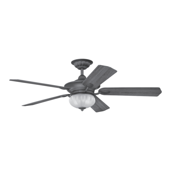
- Page 1 Elise 52“ CEILING FAN INSTALLATION AND OPERATION INSTRUCTION Read and Save These Instructions Customer Service number: 1-877-898-1881 Weight of Fan: 9.7 Kgs...
- Page 2 TURN OF THE CENTURY assumes no responsibility whatsoever for fan installation during the lifetime warranty.
-
Page 3: Tools And Materials Required
1. TOOLS AND MATERIALS REQUIRED Philips screwdriver Straight slot screwdriver Step ladder Wire cutters 2. PACKAGE CONTENTS Unpack your fan and check the contents. You should have the following items: Blade set (5) Canopy and hanger bracket assembly Downrod Collar cover Fan motor assembly Blade bracket set (5) Light kit... -
Page 4: Safety Rules
3. SAFETY RULES To reduce the risk of electric shock, insure Avoid placing objects in the path of the blades. electricity has been turned off at the circuit breaker or fuse box before beginning. To avoid personal injury or damage to the fan and other items, be cautious when working All wiring must be in accordance with the around or cleaning the fan. -
Page 5: Mounting Options
4. MOUNTING OPTIONS If there isn't an existing UL listed mounting box, then read the following instructions. Disconnect the power by removing fuses or turning off circuit breakers. Outlet box Secure the outlet box directly to the building structure. Use appropriate fasteners and building materials. -
Page 6: Hanging The Fan
5. HANGING THE FAN Ceiling hanger REMEMBER to turn off the power. Follow the steps bracket below to hang your fan properly: Ceiling canopy Step 1. Remove the decorative canopy bottom cover from the canopy by turning the cover counter clockwise. -
Page 7: Making The Electrical Connections
6. MAKING THE ELECTRICAL CONNECTIONS Frequency switch WARNING: TO AVOID POSSIBLE ELECTRICAL SHOCK, BE SURE ELECTRICITY IS TURNED OFF AT THE MAIN FUSE BOX BEFORE WIRING. If you feel you do not have enough electrical wiring knowledge or experience, have your fan installed by a licensed electrician. -
Page 8: Finishing The Installation
7. FINISHING THE INSTALLATION Outlet box Ceiling 1. Tuck connections neatly into ceiling outlet box. mounting bracket 2. Slide the canopy up to mounting bracket and Screw place the key hole on the canopy over the screw Canopy on the mounting bracket, turn canopy until it locks in place at the narrow section of the key holes. -
Page 9: Installing The Light Kit
9. INSTALLING THE LIGHT REMEMBER: To disconnect the power. The fan blades must be already attached to the fan. Your fan and light kit though pre-wired have been disassembled at the factory to ease in shipping. Please follow these steps to complete the Mounting ring installation of your fan and light. -
Page 10: Installing The Battery
10. INSTALLING THE BATTERY Install 9 volt battery (included), to prevent damage to transmitter, remove the battery if not used for long periods. (Fig. 16) 11. OPERATING INSTRUCTIONS Restore power to ceiling fan and test for proper operation. Figure 16 A. -
Page 11: Care Of Your Fan
Warm weather - (Counter-Clockwise direction) A downward airflow creates a cooling effect as shown in Fig. 18. This allows you to set your air conditioner on a warmer setting without affecting your comfort. Cool weather - (Clockwise direction) An upward airflow moves warm air off the ceiling area as shown in Fig. -
Page 12: Troubleshooting
13. TROUBLESHOOTING Problem Solution Fan will not start. 1. Check circuit fuses or breakers. 2. Check line wire connections to the fan and switch wire connections in the switch housing. CAUTION: Make sure main power is off. 3. Check to make sure the dip switches from the transmitter and receiver are set to the same frequency.
Need help?
Do you have a question about the Elise and is the answer not in the manual?
Questions and answers