Federal Signal Corporation 2-240 Installation, Operation & Service Manual
Outdoor warning sirens
Hide thumbs
Also See for 2-240:

Related Manuals for Federal Signal Corporation 2-240


Summary of Contents for Federal Signal Corporation 2-240
- Page 1 FEDERAL SIGNAL CORPORATION’S MODELS 2-120 2-240 Outdoor Warning Sirens INSTALLATION, OPERATION & SERVICE MANUAL Copyright 2006 Federal Signal Corporation 255154R 07/13...
- Page 2 IMPORTANT NOTICE Federal Signal reserves the right to make changes to devices and specifications detailed in the manual at any time in order to improve reliability, function or design. The information in this book has been carefully checked and is believed to be accurate;...
- Page 3 SAFETY NOTICES People’s lives depend on your selection of suitable equipment and installation sites and your safe installation, service, and operation of our products. Federal Signal recommends the following publications from the Federal Emergency Management Agency for assistance with planning an outdoor warning system: 1. The “Outdoor Warning Guide” (CPG 1-17), 2. “Civil Preparedness, Principles of Warning”...
- Page 4 SAFETY NOTICES People’s lives depend on your safe installation, service and operation of our products. It is important to read, understand and follow all instructions shipped with this product. In addition, listed below are some other important safety instructions and precautions you should follow: INSTALLATION &...
- Page 5 This warranty does not cover travel expenses, the cost of specialized equipment for gaining access to the product, or labor changes for removal and re-installation of the product. The Federal Signal Corporation warranty shall not apply to components or accessories that have a separate warranty by the original manufacturer, such as, but not limited to batteries.
- Page 6 WARNING Read and understand the information contained in this manual, before attempting to install or service the siren. Pay careful attention to the following notices located on the equipment NOTICES - EXTERNALLY PLACED...
-
Page 7: Table Of Contents
TABLE OF CONTENTS Paragraph Page SECTION I - GENERAL DESCRIPTION Scope of This Manual ..............1 General ..................... 1 Siren Description ................1 Mechanical Description ..............1 Control Description ................2 Signal Description ................3 SECTION II - SPECIFICATIONS Model 2 .................... 4 SECTION III - INSTALLATION Siren Location .................. -
Page 8: Scope Of This Manual
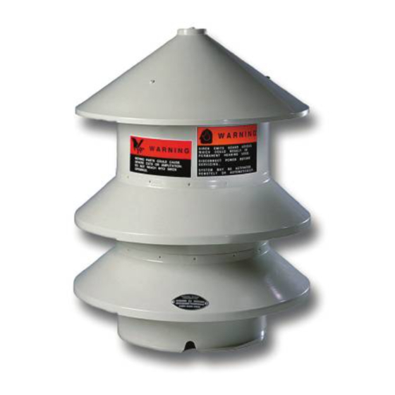
SECTION I CHARACTERISTICS Figure 1-1. Model 2 Siren 1-1. SCOPE OF THIS MANUAL This service manual describes the characteristics, specifications, installation, controls, theory of operation and servicing of the Federal Signal Model 2 Outdoor Warning Siren. 1.2. GENERAL The Federal Signal Model 2 Outdoor Warning Sirens are omni-directional sirens that are capable of producing high intensity warning signals over a large area. -
Page 9: Control Description
stator each contain at least one row of ports. As the motor rotates the rotor, air is drawn through an intake tube, and passes through the rotor and stator ports in pulses. These pulses are produced because the rotor alternately opens and closes the stator ports. -
Page 10: Signal Description
1-6. SIGNAL DESCRIPTION All of the vertical sirens are capable of providing a sustained steady signal, and a wailing signal. The steady signal is frequently used as a Civil Defense “Alert” signal. The wailing signal is often used as a Civil Defense “Attack”. -
Page 11: Section Ii - Specifications
SECTION II SPECIFICATIONS 2-1. MODEL 2. Power Requirements ..............120Vac/dc, single-phase 24A. or 240Vac/dc, single-phase 12A. Physical Diameter ................18" (46 cm) Height ................25.5" (65 cm) Shipping Weight............... 85 lb. (36 kg.) Miscellaneous Sound Output ..............102dBC at 100 ft. (30.5m - Model 2) Motor Type ............... -
Page 12: Siren Location
SECTION III INSTALLATON DANGER Electrocution or severe personal injury can occur when making electrical connections, drilling holes, or lifting equipment. Therefore, installation should be performed by experienced electricians in accordance with national and local electrical codes. 3-1. SIREN LOCATION The information in this section provides guidelines to aid the user in the selection of an installation site that makes the best possible use of the siren. -
Page 13: Physical Installation
Model 2 is approximately 910 feet (278m). Wind speed and direction often affect the propagation of sound from the siren. Consequently, the direction of the prevailing wind may also be a factor to consider when selecting the installation site(s) of a small, one or two-siren system. - Page 14 Figure 3-1. Mounting Plate Drilling Detail (d) Lay the siren mechanism on its side and attach the three legs to the mounting plate using three angle iron clips and six 1/2"-13 nuts and bolts. Attach the legs through three .75" X 1” slotted holes indicated in figure 3-1.
- Page 15 Figure 3-2. Typical Model 2 Pole-Mounted Installation...
- Page 16 Model 2 (Flat Surface Mounting) WARNING Moving parts could cause severe cuts or amputation. DO NOT reach into the siren openings. (a) Center the siren mechanism on the mounting surface, and using the mounting holes in the legs of the mechanism as a template, drill three 7/16" holes in the mounting surface (see figure 3-3). (b) Temporarily set the siren housing over the siren mechanism on the mounting plate.
- Page 17 Figure 3-3. Typical Model 2 Platform Mount...
-
Page 18: Electrical Connections
3-3. ELECTRICAL CONNECTIONS. Note: For FC, FCTB controller connections refer to their installation manuals 255294, 255326. DANGER Electrocution or severe personal injury can occur when making electrical connections, drilling holes, or lifting equipment. Therefore, installation should be performed by experienced electricians in accordance with national and local electrical codes. -
Page 19: Preoperation Checks
3. Install conduit between the disconnect switch and the electrical power source. If the siren is installed on a utility pole, add an entrance cap to the end of the conduit, as shown in figure 3-2. 4. Route two wires of the proper size from T1 and T2 in the RC2W, through the conduit to the siren motor leads. -
Page 20: Section Iv - Circuit Description
SECTION IV CIRCUIT DESCRIPTION 4-1. SIREN CONTROL DESCRIPTION The Model RC2W is used to operate a Model 2 Siren. The RC2W is a motor starter that switches the power to the Model 2 siren. The RC2W requires a siren controller to provide Steady and Wail type siren signals typically used for warning applications. The siren controller will hold a contact closed to activate the RC2W for a Steady signal and will cycle the contact open and closed to create a Wail signal. -
Page 21: Section V - Service And Maintenance
Federal Signal sirens are highly reliable devices. However, if a siren failure does occur, Federal Signal will provide technical assistance with problems that cannot be handled locally. If assistance is desired, contact: ANS Customer Care Center Signal Division Federal Signal Corporation 2645 Federal Signal Drive University Park, Illinois 60484 800-524-3021 5-1.A MINIMUM RECOMMENDED INSPECTION... -
Page 22: Corrective Maintenance
5-2. CORRECTIVE MAINTENANCE A. Troubleshooting The Troubleshooting Chart (Chart 5-1) is provided to assist repair personnel when troubleshooting a siren malfunction. This section also includes diagrams that may be helpful if the siren or control devices need repair. WARNING Moving parts could cause severe cuts or amputation. DO NOT rotate the commutator by sticking your fingers in the stator ports and pushing on any part of the rotor. - Page 23 2. Field (a) Turn off the power to the siren at the disconnect switch. (b) Remove the siren housing from the mechanism. (c) Disconnect the electrical power wiring from the siren motor. (d) Remove the siren mechanism from the mounting surface. If desired, the legs can also be removed from the mechanism.
- Page 24 NOTE: It is not necessary to follow the procedure described in steps (h) through (k) if a hydraulic press is available to press the replacement field into the motor housing. (h) Fabricate two 8" (203mm) guide pins from 3/16" (5mm) metal rod. Taper these pins as indicated in figure 5-3.
- Page 25 Siren motor inoperative. Motor starter overload Reset relay relay tripped. Open circuit between motor Check wiring for continu- starter and Motor. ity. Rotor jammed Check rotor for free rotation. Remove material causing jam- ming. Siren motor defective. Check motor, and re- pair or replace, if necessary.
- Page 26 8247A020 Cap, Brush Holder 8247A022 Housing, Motor L01-03 Legs L01-4A Hanger, Cable 8400A211 DO NOT ORDER PARTS BY INDEX NUMBER. Give model, voltage, description, and part number. Federal Signal Corporation Signal Division 2645 Federal Signal Drive University Park, Illinois 60466...
- Page 27 Figure 5-6. Model 2 Parts Index...
- Page 28 Coil, 60 Hz, 120/240V 8217C180-16 Overload Heaters (K-58) 120V 8217C182-20 Overload Heaters (K-42) 240V 8217C183-20 DO NOT ORDER PARTS BY ITEM NUMBER. Give model, voltage, description, and part number. Federal Signal Corporation Signal Division, 2645 Federal Signal Drive, University Park, Illinois 60466...
Need help?
Do you have a question about the 2-240 and is the answer not in the manual?
Questions and answers