
Related Manuals for Rotenso LCAC Series


Summary of Contents for Rotenso LCAC Series
- Page 1 LCAC IDU & ODU UNITS SERVICE MANUAL MODELS: TENJI series JATO series NEVO series ANERU series www.rotenso.com...
- Page 3 Table of Contents §. Safety Precautions Precautions Information servicing §. Model Reference & External Appearance Model Reference External Appearance §. Indoor Unit Indoor Unit - Console Type Indoor Unit - Compact Four-way Cassette Type Indoor Unit - Super Slim Four-way Cassette Type Indoor Unit - Duct Type Indoor Unit - Floor Ceiling Type §.
- Page 4 Table of Contents §. Troubleshooting Safety Caution General Troubleshooting Information Inquiry Error Diagnosis and Troubleshooting Without Error Code Quick Maintenance by Error Code Troubleshooting by Error Code Check Procedures §. Indoor Unit Disassembly Indoor Unit - Console Type Indoor Unit - Compact Four-way Cassette Type Indoor Unit - Super Slim Four-way Cassette Type Indoor Unit - Duct Type Indoor Unit - Floor Ceiling Type...
- Page 6 Safety Precautions Contents Precautions ......................2 Information servicing(For flammable materials) ..........3...
- Page 7 1. Precautions CAUTION To prevent personal injury, or property or unit damage, • • While unpacking be careful of sharp edges around adhere to all precautionary measures and instructions the unit as well as the edges of the fins on the con- denser and evaporator.
- Page 8 2. Information servicing(For • Prior to work taking place, the area around the equipment is to be surveyed to make sure that there are no flammable flammable materials) hazards or ignition risks. • NO SMOKING signs shall be displayed. Checks to the area Ventilated area •...
- Page 9 • that capacitors are discharged: this shall be done in shall also take into account the effects of aging or a safe manner to avoid possibility of sparking; continual vibration from sources such as compressors or fans. • that there no live electrical components and wiring are exposed while charging, recovering or purging 2.13 Detection of flammable refrigerants the system;...
- Page 10 • The refrigerant charge shall be recovered into the • Before attempting the procedure ensure that: correct recovery cylinders. The system shall be flushed • mechanical handling equipment is available, if with OFN to render the unit safe. This process may required, for handling refrigerant cylinders;...
- Page 11 • Empty recovery cylinders are evacuated and, if • The recovered refrigerant shall be returned to the possible, cooled before recovery occurs. refrigerant supplier in the correct recovery cylinder, and the relevant Waste Transfer Note arranged. Do not • The recovery equipment shall be in good working mix refrigerants in recovery units and especially not in order with a set of instructions concerning the cylinders.
- Page 12 Model Reference Contents Model Reference ....................2 External Appearance .....................3...
- Page 13 1. Model Reference Refer to the following table to determine the specific indoor and outdoor unit model number of your purchased equipment. Note: There are two versions of the 36k. Check you are using the right power supply for your model. Power Supply Intake : Outdoor Units Outdoor Unit Model Capacity Indoor Unit Model...
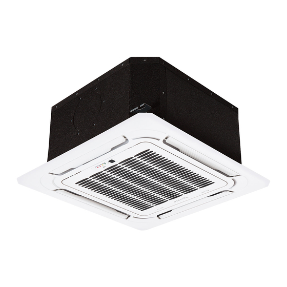
- Page 14 2. External Appearance Indoor Unit Compact Four-way Cassette Super Slim Four-way Cassette Ceiling &floor(Floor installation) Ceiling &floor(Ceiling installation) Duct Console Model Reference ...
- Page 15 Outdoor Unit Single Fan Outdoor Unit Double Fan Outdoor Unit Model Reference ...
-
Page 16: Table Of Contents
Indoor Unit-Console Contents Feature........................2 Dimensional Drawings ..................3 Part names ......................4 Service Place ......................4 Accessories ......................5 Air Velocity and Temperature Distributions ............6 Capacity Tables ......................7 Noise Criterion Curves ..................13 Electrical Characteristics ..................14 Electrical Wiring Diagrams ..................14... -
Page 17: Feature
1. Feature Stylish Design • The modern and elegant appearance is harmonious with your living space. Two air outlets, four air inlets • 2 Direction of air flow can be in two patterns: Both up and down or up only. •... -
Page 18: Dimensional Drawings
2. Dimensional Drawings Hanging arm 16 Drain pipe IDU-Console 3 ... -
Page 19: Part Names
3. Part names Air ow louver (at air outlet) Display panel Air inlet (with air lter in it) Air ow louver (at air outlet) Refrigerant connecting pipe Drain hose 4. Service Place ≥100mm ≥1000mm IDU-Console 4 ... -
Page 20: Accessories
5. Accessories The air conditioning system comes with the following accessories. Use all of the installation parts and accessories to in- stall the air conditioner. Improper installation may result in water leakage, electrical shock and fire, or equipment failure. Name Shape Quantity Soundproof/insulation sheath... -
Page 21: Air Velocity And Temperature Distributions
6. Air Velocity and Temperature Distributions Discharge Angle 60° IDU-Console 6 ... -
Page 22: Capacity Tables
7. Capacity Tables Cooling ID WB 16.0 18.0 19.0 22.0 INDOOR (℃) OUTDOOR AIRFLOW DB(℃) ID DB (CMH) 23.0 25.0 27.0 29.0 23.0 25.0 27.0 29.0 23.0 25.0 27.0 29.0 23.0 25.0 27.0 29.0 (℃) 3.71 3.72 3.72 3.75 3.90 3.96 3.96 3.96... - Page 23 3.78 3.78 3.81 3.84 3.96 3.96 3.96 3.96 4.06 4.06 4.06 4.06 4.31 4.31 4.31 4.31 0.70 0.78 0.98 1.00 0.56 0.64 0.72 0.80 0.49 0.57 0.65 0.72 0.35 0.42 0.49 0.56 0.70 0.70 0.70 0.70 0.69 0.69 0.69 0.69 0.69 0.69 0.69...
- Page 24 ID WB 16.0 18.0 19.0 22.0 INDOOR (℃) OUTDOOR AIRFLOW DB(℃) ID DB (CMH) 23.0 25.0 27.0 29.0 23.0 25.0 27.0 29.0 23.0 25.0 27.0 29.0 23.0 25.0 27.0 29.0 (℃) 5.08 5.07 5.07 5.07 5.34 5.45 5.45 5.45 5.48 5.48 5.48 5.48...
- Page 25 5.28 5.28 5.28 5.34 5.54 5.54 5.54 5.54 5.69 5.69 5.69 5.69 6.04 6.04 6.04 6.04 0.68 0.74 1.00 1.00 0.55 0.62 0.69 0.98 0.49 0.56 0.63 0.70 0.37 0.42 0.48 0.55 1.11 1.11 1.11 1.11 1.10 1.10 1.10 1.10 1.11 1.11 1.11...
- Page 26 Heating [SI_Unit] HEATING PERFORMANCE AT INDOOR DRY BULB TEMPERATURE TC:TOTAL CAPACITY IN KILOWATTS (KW) PI:TOTAL POWER IN KILOWATTS (KW) INDOOR OUTDOOR AIRFLOW (CMH) Indoor Conditions (DB °C ) Indoor Conditions (DB °C ) DB(°C) 16.0 20.0 22.0 24.0 16.0 20.0 22.0 24.0 -15.0...
- Page 27 [SI_Unit] HEATING PERFORMANCE AT INDOOR DRY BULB TEMPERATURE TC:TOTAL CAPACITY IN KILOWATTS (KW) PI:TOTAL POWER IN KILOWATTS (KW) INDOOR OUTDOOR AIRFLOW (CMH) Indoor Conditions (DB °C ) Indoor Conditions (DB °C ) DB(°C) 16.0 20.0 22.0 24.0 16.0 20.0 22.0 24.0 -15.0 3.86...
-
Page 28: Noise Criterion Curves
8. Noise Criterion Curves Notes: -Sound measured at 1.5m away from the noisiest location of the unit. -Data is valid at free field condition -Data is valid at nominal operation condition -Reference acoustic pressure OdB = 20µPa -Sound level will vary depending on a range of factors such as the construction -(acoustic absorption coefficient) of particular room in which the equipment is installed. -
Page 29: Electrical Characteristics
9. Electrical Characteristics Capacity (Btu/h) 12k~18k Phase 1-phase Frequency and Voltage 220-240V, 50Hz OUDOOR UNIT POWER Power Wiring (mm 3×1.5 Circuit Breaker/ Fuse (A) 25/20 Weak Electric Signal)(mm Indoor/Outdoor Connecting Wiring Strong Electric Signal(mm 4×1.0 10. Electrical Wiring Diagrams IDU Model IDU Wiring Diagram A35Xi 16022700002988... - Page 30 Indoor unit wiring diagram: 16022700002988 CODE:16022700002988 WIRING DIAGRAM (INDOOR UNIT) Remote DISPLAY BOARD Magnetic ring Control WIRE CODE PART NAME FUNCTION OF SWITCHES CONTROLLER CN1-CN201 P.C BOARD SOCKETS SWITCH BOARD INDOOR DC FAN MOTOR Magnetic ring ON/OFF UPPER OUTLET SWING MOTOR SW102 SW103 CN16...
- Page 31 10.2 Micro-Switch Introduce: A. Micro-switch SW1 is for selection of auto-restart function. Range: Active, inactive B. Take off the panel, you can see the switch SW101 which is used for selecting both air outlets or upper air outlet only. C. Micro-switch SW102 is for selection of temperature compensation in heating mode. This helps to reduce the real temperature difference between ceiling and floor so that the unit could run properly.
- Page 32 10.1 Micro-Switch Introduce: A. For remote control (ON-OFF) terminal port CN23 and short connector of JR6 1. Remove the short connector of JR6 when you use ON-OFF function; 2. When remote switch off (OPEN); the unit would be off; 3. When remote switch on (CLOSE); the unit would be on; 4.
- Page 33 Indoor Unit-Compact Cassette Contents Feature........................2 Dimensional Drawings ..................4 Part names ......................5 Service Place ......................6 Accessories ......................7 Air Velocity and Temperature Distributions ............8 Capacity Tables ....................16 Noise Criterion Curves ..................22 Electrical Characteristics ..................23 Electrical Wiring Diagrams ..................23...
-
Page 34: Feature
1. Feature Compact design • The body size is 570×260×570mm, it’s just smaller than the ceiling board, so it’s very easy for installation and will not damage the decoration. The panel size is 647×50×647mm. • The hooks are designed in the four corners of the body, which can save installation space. Fire-proof Controller Box •... - Page 35 Fresh Air • Fresh air intake function brings you fresh and comfortable air feeling. Wired Controller(Optional) • Compared with infrared remote controller, wired controller can be fixed on the wall and avoid mislaying. It's mainly used for commercial zone and makes air conditioner control more convenient. Louver Position Memory (Standard for ERP models) •...
-
Page 36: Dimensional Drawings
2. Dimensional Drawings IDU-Compact Cassette 4 ... -
Page 37: Part Names
3. Part names Drain pump (within indoor unit) Drain pipe Air outlet Air inlet Front grille Louver Display panel Refrigerant pipe IDU-Compact Cassette 5 ... -
Page 38: Service Place
4. Service Place IDU-Compact Cassette 6 ... -
Page 39: Accessories
5. Accessories The air conditioning system comes with the following accessories. Use all of the installation parts and accessories to in- stall the air conditioner. Improper installation may result in water leakage, electrical shock and fire, or equipment failure. Name Shape Quantity Installation paper template (some... -
Page 40: Air Velocity And Temperature Distributions
6. Air Velocity and Temperature Distributions Discharge Angle 30° Cooling airflow velocity distributions Cooling temperature distributions IDU-Compact Cassette 8 ... - Page 41 Heating airflow velocity distributions Heating temperature distributions IDU-Compact Cassette 9 ...
- Page 42 Discharge Angle 60° Cooling airflow velocity distributions Cooling temperature distributions IDU-Compact Cassette 10 ...
- Page 43 Heating airflow velocity distributions Heating temperature distributions IDU-Compact Cassette 11 ...
- Page 44 Discharge Angle 30° Cooling airflow velocity distributions Cooling temperature distributions IDU-Compact Cassette 12 ...
- Page 45 Heating airflow velocity distributions Heating temperature distributions IDU-Compact Cassette 13 ...
- Page 46 Discharge Angle 60° Cooling airflow velocity distributions Cooling temperature distributions IDU-Compact Cassette 14 ...
- Page 47 Heating airflow velocity distributions Heating temperature distributions IDU-Compact Cassette 15 ...
-
Page 48: Capacity Tables
8. Capacity Tables Cooling ID WB 16.0 18.0 19.0 22.0 INDOOR (℃) OUTDOOR AIRFLOW DB(℃) ID DB (CMH) 23.0 25.0 27.0 29.0 23.0 25.0 27.0 29.0 23.0 25.0 27.0 29.0 23.0 25.0 27.0 29.0 (℃) 3.71 3.72 3.72 3.75 3.90 3.96 3.96 3.96... - Page 49 3.78 3.78 3.81 3.84 3.96 3.96 3.96 3.96 4.06 4.06 4.06 4.06 4.31 4.31 4.31 4.31 0.70 0.79 0.98 1.00 0.56 0.65 0.73 0.81 0.50 0.58 0.66 0.74 0.35 0.42 0.49 0.57 0.69 0.69 0.69 0.69 0.69 0.69 0.69 0.69 0.69 0.69 0.69...
- Page 50 ID WB 16.0 18.0 19.0 22.0 INDOOR (℃) OUTDOOR AIRFLOW DB(℃) ID DB (CMH) 23.0 25.0 27.0 29.0 23.0 25.0 27.0 29.0 23.0 25.0 27.0 29.0 23.0 25.0 27.0 29.0 (℃) 5.50 5.50 5.50 5.50 5.78 5.90 5.90 5.90 5.93 5.93 5.93 5.93...
- Page 51 5.74 5.74 5.74 5.80 6.05 6.05 6.05 6.05 6.20 6.20 6.20 6.20 6.57 6.57 6.57 6.57 0.69 0.77 1.00 1.00 0.56 0.63 0.70 0.98 0.49 0.57 0.64 0.71 0.36 0.42 0.49 0.56 1.14 1.14 1.14 1.14 1.13 1.13 1.13 1.13 1.13 1.13 1.13...
- Page 52 Heating [SI_Unit] HEATING PERFORMANCE AT INDOOR DRY BULB TEMPERATURE TC:TOTAL CAPACITY IN KILOWATTS (KW) PI:TOTAL POWER IN KILOWATTS (KW) INDOOR OUTDOOR AIRFLOW (CMH) Indoor Conditions (DB °C ) Indoor Conditions (DB °C ) DB(°C) 16.0 20.0 22.0 24.0 16.0 20.0 22.0 24.0 -15.0...
- Page 53 [SI_Unit] HEATING PERFORMANCE AT INDOOR DRY BULB TEMPERATURE TC:TOTAL CAPACITY IN KILOWATTS (KW) PI:TOTAL POWER IN KILOWATTS (KW) INDOOR OUTDOOR AIRFLOW (CMH) Indoor Conditions (DB °C ) Indoor Conditions (DB °C ) DB(°C) 16.0 20.0 22.0 24.0 16.0 20.0 22.0 24.0 -15.0 3.61...
-
Page 54: Noise Criterion Curves
9. Noise Criterion Curves Indoor Unit Notes: -Sound measured at 1.4m away from the noisiest location of the unit. -Data is valid at free field condition -Data is valid at nominal operation condition -Reference acoustic pressure OdB = 20µPa -Sound level will vary depending on a range of factors such as the construction -(acoustic absorption coefficient) of particular room in which the equipment is installed. -
Page 55: Electrical Characteristics
10. Electrical Characteristics Capacity (Btu/h) 12k~18k Phase 1-phase Frequency and Voltage 220-240V, 50Hz OUDOOR UNIT POWER Power Wiring (mm 3×1.5 Circuit Breaker/ Fuse (A) 25/20 Weak Electric Signal)(mm Indoor/Outdoor Connecting Wiring Strong Electric Signal(mm 4×1.0 11. Electrical Wiring Diagrams IDU Model IDU Wiring Diagram T21Xi/T26Xi/T35Xi 16022500004023... - Page 57 10.1 Some connectors introduce: A For remote control (ON-OFF) terminal port CN23 and short connector of JR6 1. Remove the short connector of JR6 when you use ON-OFF function; 2. When remote switch off (OPEN) ;the unit would be off; 3.
- Page 58 B For ALARM terminal port CN33 1. Provide the terminal port to connect ALARM ,but no voltage of the terminal port , the power from the ALARM system (not from the unit ) 2. Although design voltage can support higher voltage ,but we strongly ask you connect the power less than 24V, current less than 0.5A 3.
- Page 59 C. For new fresh motor terminal port CN8 1. Connect the fan motor to the port , no need care L/N of the motor ; 2. The output voltage is the power supply; 3. The fresh motor can not excess 200W or 1A , follow the smaller one ; 4.
- Page 60 10.2 Micro-Switch Introduce: A. Micro-switch SW1 is for selection of indoor fan stop temperature (TEL0) when it is in anti-cold wind action in heating mode. Range: 24 C, 15 C, 8 C, According to EEROM setting (reserved for special customizing). B.Micro-switch SW2 is for selection of indoor FAN ACTION if room temperature reaches the setponit and the compressor stops.
- Page 61 C.Micro-switch SW3 is for selection of auto-restart function. Range: Active, inactive SWITCH FOR MODE-PRIOR SETTING STATE COOL MODE HEAT HEAT COOL Factory Setting D. Micro-switch SW5 is for setting mode priority of multi connection. Range: Heat, cool. E.Micro-switch SW6 is for selection of temperature compensation in heating mode. This helps to reduce the real temperature difference between ceiling and floor so that the unit could run properly.
- Page 62 G.Micro-switch S1 and dial-switch S2 are for address setting when you want to control this unit by a central controller. Range: 00-63 32~35 36~53 54~71 72~90 91~105 106~140 141~160 161~200 H. Dial-switch ENC1: The indoor PCB is universal designed for whole series units from 7K to 68K. This ENC1 setting will tell the main program what size the unit is.
- Page 63 Indoor Unit-Super Slim Cassette Contents Feature........................2 Dimensional Drawings ..................5 Part names ......................6 Service Place ......................6 Accessories ......................7 Air Velocity and Temperature Distributions ............8 Capacity Tables ....................32 Noise Criterion Curves ..................53 Electrical Characteristics ..................55 Electrical Wiring Diagrams ..................56...
-
Page 64: Feature
1. Feature Air Flow • 360°directional wind can deliver air evenly throughout every corner in any space, reducing hot and cold spots in the room. Easy Installation • The Cassette is much slimmer due to the redesigned heat exchanger and overall structures. It now requires less space for installation. - Page 65 Fresh Air • Fresh air intake function brings you fresh and comfortable air feeling. Wired Controller(Optional) • Compared with infrared remote controller, wired controller can be fixed on the wall and avoid mislaying. It's mainly used for commercial zone and makes air conditioner control more convenient. ...
-
Page 66: Dimensional Drawings
2. Dimensional Drawings Model Unit (KBtu/h) inch 6.50 3.15 8.07 1.97 30~36 inch 6.50 3.94 9.65 2.36 42~60 inch 6.50 3.94 11.30 2.36 IDU-Super Slim Cassette 5 ... -
Page 67: Part Names
3. Part names Display panel Louver Air outlet Air inlet 4. Service Place Ceiling Ventilator Indoor unit Indoor unit Illumination Ceiling >150cm / 59.1” >150cm / 59.1” >200cm / 78.7” (200cm / 78.7” recommended) >400cm / 157.5” >230cm / 90.6” Ground ... -
Page 68: Accessories
5. Accessories The air conditioning system comes with the following accessories. Use all of the installation parts and accessories to in- stall the air conditioner. Improper installation may result in water leakage, electrical shock and fire, or equipment failure. Name Shape Quantity Installation paper template (some... -
Page 69: Air Velocity And Temperature Distributions
6. Air Velocity and Temperature Distributions Discharge Angle 30° Cooling airflow velocity distributions Cooling temperature distributions IDU-Super Slim Cassette 8 ... - Page 70 Discharge Angle 30° Heating airflow velocity distributions Heating temperature distributions IDU-Super Slim Cassette 9 ...
- Page 71 Discharge Angle 60° Cooling airflow velocity distributions Cooling temperature distributions IDU-Super Slim Cassette 10 ...
- Page 72 Discharge Angle 60° Heating airflow velocity distributions Heating temperature distributions IDU-Super Slim Cassette 11 ...
- Page 73 Discharge Angle 30° Cooling airflow velocity distributions Cooling temperature distributions IDU-Super Slim Cassette 12 ...
- Page 74 Discharge Angle 30° Heating airflow velocity distributions Heating temperature distributions IDU-Super Slim Cassette 13 ...
- Page 75 Discharge Angle 60° Cooling airflow velocity distributions Cooling temperature distributions IDU-Super Slim Cassette 14 ...
- Page 76 Discharge Angle 60° Heating airflow velocity distributions Heating temperature distributions IDU-Super Slim Cassette 15 ...
- Page 77 Discharge Angle 30° Cooling airflow velocity distributions Cooling temperature distributions IDU-Super Slim Cassette 16 ...
- Page 78 Discharge Angle 30° Heating airflow velocity distributions Heating temperature distributions IDU-Super Slim Cassette 17 ...
- Page 79 Discharge Angle 60° Cooling airflow velocity distributions Cooling temperature distributions IDU-Super Slim Cassette 18 ...
- Page 80 Discharge Angle 60° Heating airflow velocity distributions Heating temperature distributions IDU-Super Slim Cassette 19 ...
- Page 81 Discharge Angle 30° Cooling airflow velocity distributions Cooling temperature distributions IDU-Super Slim Cassette 20 ...
- Page 82 Discharge Angle 30° Heating airflow velocity distributions Heating temperature distributions IDU-Super Slim Cassette 21 ...
- Page 83 Discharge Angle 60° Cooling airflow velocity distributions Cooling temperature distributions IDU-Super Slim Cassette 22 ...
- Page 84 Discharge Angle 60° Heating airflow velocity distributions Heating temperature distributions IDU-Super Slim Cassette 23 ...
- Page 85 Discharge Angle 30° Cooling airflow velocity distributions Cooling temperature distributions IDU-Super Slim Cassette 24 ...
- Page 86 Discharge Angle 30° Heating airflow velocity distributions Heating temperature distributions IDU-Super Slim Cassette 25 ...
- Page 87 Discharge Angle 60° Cooling airflow velocity distributions Cooling temperature distributions IDU-Super Slim Cassette 26 ...
- Page 88 Discharge Angle 60° Heating airflow velocity distributions Heating temperature distributions IDU-Super Slim Cassette 27 ...
- Page 89 Discharge Angle 30° Cooling airflow velocity distributions Cooling temperature distributions IDU-Super Slim Cassette 28 ...
- Page 90 Discharge Angle 30° Heating airflow velocity distributions Heating temperature distributions IDU-Super Slim Cassette 29 ...
- Page 91 Discharge Angle 60° Cooling airflow velocity distributions Cooling temperature distributions IDU-Super Slim Cassette 30 ...
- Page 92 Discharge Angle 60° Heating airflow velocity distributions Heating temperature distributions IDU-Super Slim Cassette 31 ...
-
Page 93: Capacity Tables
7. Capacity Tables Cooling ID WB 16.0 18.0 19.0 22.0 INDOOR (℃) OUTDOOR AIRFLOW DB(℃) ID DB (CMH) 23.0 25.0 27.0 29.0 23.0 25.0 27.0 29.0 23.0 25.0 27.0 29.0 23.0 25.0 27.0 29.0 (℃) 7.35 7.34 7.40 7.46 7.73 7.88 7.88 7.97... - Page 94 7.50 7.50 7.56 7.65 7.88 7.88 7.88 7.97 8.09 8.09 8.09 8.09 8.58 8.58 8.58 8.58 0.73 0.84 0.98 1.00 0.58 0.68 0.77 0.86 0.50 0.60 0.69 0.78 0.34 0.42 0.51 0.60 1.58 1.58 1.58 1.58 1.57 1.57 1.57 1.57 1.57 1.57 1.57...
- Page 95 ID WB 16.0 18.0 19.0 22.0 INDOOR (℃) OUTDOOR AIRFLOW DB(℃) ID DB (CMH) 23.0 25.0 27.0 29.0 23.0 25.0 27.0 29.0 23.0 25.0 27.0 29.0 23.0 25.0 27.0 29.0 (℃) 9.20 9.22 9.31 9.40 9.68 9.89 9.89 9.98 9.90 9.90 9.90 9.90...
- Page 96 9.58 9.67 9.76 9.85 10.07 10.07 10.07 10.16 10.32 10.32 10.32 10.32 10.97 10.97 10.97 10.97 0.78 0.90 1.00 1.00 0.60 0.71 0.83 0.98 0.52 0.63 0.74 0.85 0.33 0.42 0.53 0.64 1.90 1.90 1.90 1.90 1.90 1.90 1.90 1.90 1.90 1.90 1.90...
- Page 97 36k+UO100Xo ID WB 16.0 18.0 19.0 22.0 INDOOR (℃) OUTDOOR AIRFLOW DB(℃) ID DB (CMH) 23.0 25.0 27.0 29.0 23.0 25.0 27.0 29.0 23.0 25.0 27.0 29.0 23.0 25.0 27.0 29.0 (℃) 11.05 11.06 11.06 11.18 11.63 11.87 11.87 11.87 11.90 11.90 11.90...
- Page 98 11.49 11.49 11.61 11.73 12.08 12.08 12.08 12.20 12.38 12.38 12.38 12.38 13.15 13.15 13.15 13.15 0.73 0.83 1.00 1.00 0.58 0.68 0.76 0.98 0.50 0.60 0.69 0.78 0.34 0.42 0.51 0.60 2.74 2.74 2.74 2.74 2.73 2.73 2.73 2.73 2.72 2.72 2.72...
- Page 99 36k+UO100Xo3F ID WB 16.0 18.0 19.0 22.0 INDOOR (℃) OUTDOOR AIRFLOW DB(℃) ID DB (CMH) 23.0 25.0 27.0 29.0 23.0 25.0 27.0 29.0 23.0 25.0 27.0 29.0 23.0 25.0 27.0 29.0 (℃) 11.05 11.06 11.06 11.18 11.63 11.87 11.87 11.87 11.90 11.90 11.90...
- Page 100 11.49 11.49 11.61 11.73 12.08 12.08 12.08 12.20 12.38 12.38 12.38 12.38 13.15 13.15 13.15 13.15 0.73 0.83 1.00 1.00 0.58 0.68 0.76 0.98 0.50 0.60 0.69 0.78 0.34 0.42 0.51 0.60 2.77 2.77 2.77 2.77 2.77 2.77 2.77 2.77 2.76 2.76 2.76...
- Page 101 ID WB 16.0 18.0 19.0 22.0 INDOOR (℃) OUTDOOR AIRFLOW DB(℃) ID DB (CMH) 23.0 25.0 27.0 29.0 23.0 25.0 27.0 29.0 23.0 25.0 27.0 29.0 23.0 25.0 27.0 29.0 (℃) 12.59 12.60 12.72 12.84 13.24 13.51 13.51 13.51 13.57 13.57 13.57 13.57...
- Page 102 13.08 13.08 13.20 13.33 13.78 13.78 13.78 13.78 14.11 14.11 14.11 14.11 14.97 14.97 14.97 14.97 0.73 0.83 1.00 1.00 0.58 0.67 0.76 0.98 0.50 0.60 0.69 0.77 0.34 0.42 0.50 0.59 2.91 2.91 2.91 2.91 2.91 2.91 2.91 2.91 2.90 2.90 2.90...
- Page 103 ID WB 16.0 18.0 19.0 22.0 INDOOR (℃) OUTDOOR AIRFLOW DB(℃) ID DB (CMH) 23.0 25.0 27.0 29.0 23.0 25.0 27.0 29.0 23.0 25.0 27.0 29.0 23.0 25.0 27.0 29.0 (℃) 14.70 14.69 14.69 14.84 15.46 15.79 15.79 15.79 15.84 15.84 15.84 15.84...
- Page 104 15.33 15.33 15.48 15.63 16.12 16.12 16.12 16.12 16.53 16.53 16.53 16.53 17.54 17.54 17.54 17.54 0.70 0.78 1.00 1.00 0.56 0.64 0.71 0.98 0.49 0.57 0.65 0.72 0.35 0.42 0.49 0.56 3.23 3.23 3.23 3.23 3.21 3.21 3.21 3.21 3.22 3.22 3.22...
- Page 105 ID WB 16.0 18.0 19.0 22.0 INDOOR (℃) OUTDOOR AIRFLOW DB(℃) ID DB (CMH) 23.0 25.0 27.0 29.0 23.0 25.0 27.0 29.0 23.0 25.0 27.0 29.0 23.0 25.0 27.0 29.0 (℃) 15.98 15.98 15.98 16.13 16.80 17.13 17.13 17.13 17.20 17.20 17.20 17.20...
- Page 106 16.62 16.62 16.80 16.98 17.46 17.46 17.46 17.46 17.89 17.89 17.89 17.89 19.01 19.01 19.01 19.01 0.70 0.77 1.00 1.00 0.56 0.64 0.71 0.98 0.49 0.57 0.65 0.72 0.35 0.42 0.49 0.56 3.47 3.47 3.47 3.47 3.45 3.45 3.45 3.45 3.45 3.45 3.45...
- Page 107 Heating [SI_Unit] HEATING PERFORMANCE AT INDOOR DRY BULB TEMPERATURE TC:TOTAL CAPACITY IN KILOWATTS (KW) PI:TOTAL POWER IN KILOWATTS (KW) INDOOR OUTDOOR AIRFLOW (CMH) Indoor Conditions (DB °C ) Indoor Conditions (DB °C ) DB(°C) 16.0 20.0 22.0 24.0 16.0 20.0 22.0 24.0 -15.0...
- Page 108 [SI_Unit] HEATING PERFORMANCE AT INDOOR DRY BULB TEMPERATURE TC:TOTAL CAPACITY IN KILOWATTS (KW) PI:TOTAL POWER IN KILOWATTS (KW) INDOOR OUTDOOR AIRFLOW (CMH) Indoor Conditions (DB °C ) Indoor Conditions (DB °C ) DB(°C) 16.0 20.0 22.0 24.0 16.0 20.0 22.0 24.0 -15.0 5.65...
- Page 109 [SI_Unit] 36k+UO100Xo HEATING PERFORMANCE AT INDOOR DRY BULB TEMPERATURE TC:TOTAL CAPACITY IN KILOWATTS (KW) PI:TOTAL POWER IN KILOWATTS (KW) INDOOR OUTDOOR AIRFLOW (CMH) Indoor Conditions (DB °C ) Indoor Conditions (DB °C ) DB(°C) 16.0 20.0 22.0 24.0 16.0 20.0 22.0 24.0 -15.0...
- Page 110 [SI_Unit] 36k+UO100Xo3F HEATING PERFORMANCE AT INDOOR DRY BULB TEMPERATURE TC:TOTAL CAPACITY IN KILOWATTS (KW) PI:TOTAL POWER IN KILOWATTS (KW) INDOOR OUTDOOR AIRFLOW (CMH) Indoor Conditions (DB °C ) Indoor Conditions (DB °C ) DB(°C) 16.0 20.0 22.0 24.0 16.0 20.0 22.0 24.0 -15.0...
- Page 111 [SI_Unit] HEATING PERFORMANCE AT INDOOR DRY BULB TEMPERATURE TC:TOTAL CAPACITY IN KILOWATTS (KW) PI:TOTAL POWER IN KILOWATTS (KW) INDOOR OUTDOOR AIRFLOW (CMH) Indoor Conditions (DB °C ) Indoor Conditions (DB °C ) DB(°C) 16.0 20.0 22.0 24.0 16.0 20.0 22.0 24.0 -15.0 8.18...
- Page 112 [SI_Unit] HEATING PERFORMANCE AT INDOOR DRY BULB TEMPERATURE TC:TOTAL CAPACITY IN KILOWATTS (KW) PI:TOTAL POWER IN KILOWATTS (KW) INDOOR OUTDOOR AIRFLOW (CMH) Indoor Conditions (DB °C ) Indoor Conditions (DB °C ) DB(°C) 16.0 20.0 22.0 24.0 16.0 20.0 22.0 24.0 -15.0 10.93...
- Page 113 [SI_Unit] HEATING PERFORMANCE AT INDOOR DRY BULB TEMPERATURE TC:TOTAL CAPACITY IN KILOWATTS (KW) PI:TOTAL POWER IN KILOWATTS (KW) INDOOR OUTDOOR AIRFLOW (CMH) Indoor Conditions (DB °C ) Indoor Conditions (DB °C ) DB(°C) 16.0 20.0 22.0 24.0 16.0 20.0 22.0 24.0 -15.0 11.84...
-
Page 114: Noise Criterion Curves
7. Noise Criterion Curves Indoor Unit Notes: -Sound measured at 1.5m away from the center of the unit. -Data is valid at free field condition -Data is valid at nominal operation condition -Reference acoustic pressure OdB = 20µPa -Sound level will vary depending on a range of factors such as the construction -(acoustic absorption coefficient) of particular room in which the equipment is installed. - Page 115 IDU-Super Slim Casstte 54 ...
-
Page 116: Electrical Characteristics
7. Electrical Characteristics Capacity (Btu/h) Phase 1-phase 1-phase 1-phase Frequency and Voltage 220-240V, 50Hz 220-240V, 50Hz 220-240V, 50Hz OUDOOR UNIT POWER Power Wiring (mm 3×2.5 3×2.5 3×4.0 Circuit Breaker/ Fuse 25/20 50/40 50/40 Weak Electric Signal) Indoor/Outdoor Connecting Wiring Strong Electric 4×1.0 4×1.0 4×1.0... -
Page 117: Electrical Wiring Diagrams
7. Electrical Wiring Diagrams IDU Capacity (Btu/h) IDU Wiring Diagram 24k~55k 16022500004263 Abbreviation Paraphrase Yellow-Green Conductor CAP1 Indoor Fan Capacitor FAN1 Indoor Fan PUMP PUMP LIVE NEUTRAL TO CCM Comm.Bus Central Controller Indoor Room Temperature Coil Temperature of Indoor Heat Exchanger Super High Speed High Speed ... - Page 119 10.1 Some connectors introduce: A For remote control (ON-OFF) terminal port CN23 and short connector of JR6 1. Remove the short connector of JR6 when you use ON-OFF function; 2. When remote switch off (OPEN) ;the unit would be off; 3.
- Page 120 B For ALARM terminal port CN33 1. Provide the terminal port to connect ALARM ,but no voltage of the terminal port , the power from the ALARM system (not from the unit ) 2. Although design voltage can support higher voltage ,but we strongly ask you connect the power less than 24V, current less than 0.5A 3.
- Page 121 C. For new fresh motor terminal port CN8 1. Connect the fan motor to the port , no need care L/N of the motor ; 2. The output voltage is the power supply; 3. The fresh motor can not excess 200W or 1A , follow the smaller one ; 4.
- Page 122 10.2 Micro-Switch Introduce: A. Micro-switch SW1 is for selection of indoor fan stop temperature (TEL0) when it is in anti-cold wind action in heating mode. Range: 24 C, 15 C, 8 C, According to EEROM setting (reserved for special customizing). B.Micro-switch SW2/SW2-1 is for selection of indoor FAN ACTION if room temperature reaches the setponit and the compressor stops.
- Page 123 C.Micro-switch SW2-2 is for selection of Breezeless function. Range: OFF, ON. D.Micro-switch SW3 is for selection of auto-restart function. Range: Active, inactive SWITCH FOR MODE-PRIOR SETTING STATE COOL MODE HEAT HEAT COOL Factory Setting E. Micro-switch SW5 is for setting mode priority of multi connection. Range: Heat, cool.
- Page 124 FOR COOLING & HEATING OR COOLING ONLY SWITCH SETTING S TAT E C OOLIN G& C O O L I N G MO DE H EATIN G O N L Y F act o r y S ett i n g G.Micro-switch SW7 is for setting cooling &heating or cooling only.
- Page 125 Indoor Unit - Duct Contents Feature........................2 Dimensional Drawings ..................4 Part names ......................5 Service Place ......................5 Accessories ......................6 Fan Performance ....................7 Capacity Tables ....................13 Noise Criterion Curves ..................40 Electrical Characteristics ..................43 Electrical Wiring Diagrams ..................44...
-
Page 126: Feature
1. Feature Eccentric Fan Design New eccentric fan design improves the airflow at the air outlet, resulting better performance. Slim Design The industry lowest height is designed to be fitted into tight roof space. Flexible Air Intake The frame size of air inlet in rear and bottom is the same. It’s very easy to switch to match different applications. - Page 127 Built-in Drain Pump The built-in drain pump can lift condensing water up to 750mm. Easy Clean You can pull out the filter from left, right, or from the bottom for easy cleaning. IDU-Duct 3 ...
-
Page 128: Dimensional Drawings
2. Dimensional Drawings Model unit (KBtu/h) inch 27.56 7.87 19.92 17.72 5.39 21.14 1.18 5.98 23.58 7.32 1.97 29.17 14.17 3.31 5.51 3.31 3.31 inch 34.65 8.27 26.54 23.62 5.51 27.8 1.97 5.35 30.79 7.48 1.57 36.22 3.07 5.83 3.46 4.41 1100 1001... -
Page 129: Part Names
3. Part names Air inlet Electric control box Air lter(on some models) Drain hose Air outlet Refrigerant connecting pipe 4. Service Place Air outlet (30cm) 11.8 (20cm) Air inlet 23.6 x23.6 (60cmx60cm) checking orifice IDU-Duct 5 ... -
Page 130: Accessories
5. Accessories The air conditioning system comes with the following accessories. Use all of the installation parts and accessories to in- stall the air conditioner. Improper installation may result in water leakage, electrical shock and fire, or equipment failure. Name Shape Quantity Soundproof / insulation sheath... -
Page 131: Fan Performance
6. Fan Performance IDU-Duct 7 ... - Page 132 IDU-Duct 8 ...
- Page 133 IDU-Duct 9 ...
- Page 134 30K/36K IDU-Duct 10 ...
- Page 135 42K/48K IDU-Duct 11 ...
- Page 136 IDU-Duct 12 ...
-
Page 137: Capacity Tables
7. Capacity Tables Cooling ID WB 16.0 18.0 19.0 22.0 INDOOR (℃) OUTDOOR AIRFLOW DB(℃) ID DB (CMH) 23.0 25.0 27.0 29.0 23.0 25.0 27.0 29.0 23.0 25.0 27.0 29.0 23.0 25.0 27.0 29.0 (℃) 3.71 3.72 3.72 3.72 3.90 3.96 3.96 3.96... - Page 138 3.78 3.78 3.81 3.84 3.96 3.96 3.96 3.96 4.06 4.06 4.06 4.06 4.31 4.31 4.31 4.31 0.70 0.79 0.98 1.00 0.56 0.65 0.72 0.81 0.50 0.58 0.66 0.73 0.35 0.42 0.49 0.57 0.72 0.72 0.72 0.72 0.72 0.72 0.72 0.72 0.72 0.72 0.72...
- Page 139 ID WB 16.0 18.0 19.0 22.0 INDOOR (℃) OUTDOOR AIRFLOW DB(℃) ID DB (CMH) 23.0 25.0 27.0 29.0 23.0 25.0 27.0 29.0 23.0 25.0 27.0 29.0 23.0 25.0 27.0 29.0 (℃) 5.50 5.50 5.50 5.50 5.78 5.90 5.90 5.90 5.93 5.93 5.93 5.93...
- Page 140 5.74 5.80 5.86 5.92 6.05 6.05 6.05 6.11 6.20 6.20 6.20 6.20 6.57 6.57 6.57 6.57 0.75 0.85 1.00 1.00 0.59 0.69 0.79 0.98 0.51 0.61 0.70 0.80 0.33 0.42 0.51 0.61 1.06 1.06 1.06 1.06 1.06 1.06 1.06 1.06 1.06 1.06 1.06...
- Page 141 7.35 7.34 7.34 7.40 7.73 7.88 7.88 7.88 7.93 7.93 7.93 7.93 8.40 8.40 8.40 8.40 0.69 0.75 0.83 0.91 0.55 0.63 0.70 0.77 0.49 0.56 0.64 0.70 0.36 0.42 0.48 0.55 1.46 1.47 1.47 1.46 1.46 1.46 1.46 1.46 1.46 1.46 1.46...
- Page 142 7.68 7.77 7.86 7.95 8.06 8.06 8.06 8.15 8.26 8.26 8.26 8.26 8.79 8.79 8.79 8.79 0.75 0.86 1.00 1.00 0.59 0.69 0.79 0.98 0.51 0.61 0.70 0.81 0.33 0.42 0.52 0.61 1.52 1.52 1.52 1.52 1.51 1.51 1.51 1.51 1.51 1.51 1.51...
- Page 143 ID WB 16.0 18.0 19.0 22.0 INDOOR (℃) OUTDOOR AIRFLOW DB(℃) ID DB (CMH) 23.0 25.0 27.0 29.0 23.0 25.0 27.0 29.0 23.0 25.0 27.0 29.0 23.0 25.0 27.0 29.0 (℃) 9.20 9.31 9.40 9.49 9.68 9.89 9.98 10.07 9.90 9.90 9.90 9.90...
- Page 144 9.58 9.67 9.76 9.85 10.07 10.07 10.16 10.25 10.32 10.32 10.32 10.41 10.97 10.97 10.97 10.97 0.86 0.97 1.00 1.00 0.65 0.78 0.92 0.98 0.54 0.68 0.82 0.95 0.31 0.44 0.57 0.70 1.73 1.73 1.73 1.73 1.73 1.73 1.73 1.73 1.73 1.73 1.73...
- Page 145 36k+UO100Xo ID WB 16.0 18.0 19.0 22.0 INDOOR (℃) OUTDOOR AIRFLOW DB(℃) ID DB (CMH) 23.0 25.0 27.0 29.0 23.0 25.0 27.0 29.0 23.0 25.0 27.0 29.0 23.0 25.0 27.0 29.0 (℃) 11.05 11.06 11.18 11.30 11.63 11.87 11.87 11.99 11.90 11.90 11.90...
- Page 146 11.49 11.61 11.73 11.85 12.08 12.08 12.08 12.20 12.38 12.38 12.38 12.50 13.15 13.15 13.15 13.15 0.79 0.92 1.00 1.00 0.61 0.72 0.84 0.98 0.52 0.64 0.75 0.86 0.33 0.43 0.53 0.64 2.74 2.74 2.74 2.74 2.73 2.73 2.73 2.73 2.72 2.72 2.72...
- Page 147 36k+UO100Xo3F ID WB 16.0 18.0 19.0 22.0 INDOOR (℃) OUTDOOR AIRFLOW DB(℃) ID DB (CMH) 23.0 25.0 27.0 29.0 23.0 25.0 27.0 29.0 23.0 25.0 27.0 29.0 23.0 25.0 27.0 29.0 (℃) 11.05 11.06 11.18 11.30 11.63 11.87 11.87 11.99 11.90 11.90 11.90...
- Page 148 11.49 11.61 11.73 11.85 12.08 12.08 12.08 12.20 12.38 12.38 12.38 12.50 13.15 13.15 13.15 13.15 0.79 0.92 1.00 1.00 0.61 0.72 0.84 0.98 0.52 0.64 0.75 0.86 0.33 0.43 0.53 0.64 2.77 2.77 2.77 2.77 2.77 2.77 2.77 2.77 2.76 2.76 2.76...
- Page 149 ID WB 16.0 18.0 19.0 22.0 INDOOR (℃) OUTDOOR AIRFLOW DB(℃) ID DB (CMH) 23.0 25.0 27.0 29.0 23.0 25.0 27.0 29.0 23.0 25.0 27.0 29.0 23.0 25.0 27.0 29.0 (℃) 12.59 12.60 12.72 12.84 13.24 13.51 13.51 13.66 13.57 13.57 13.57 13.57...
- Page 150 13.08 13.20 13.33 13.45 13.78 13.78 13.78 13.93 14.11 14.11 14.11 14.26 14.97 14.97 14.97 14.97 0.79 0.92 1.00 1.00 0.61 0.72 0.84 0.98 0.52 0.64 0.75 0.86 0.33 0.43 0.54 0.65 2.91 2.91 2.91 2.91 2.91 2.91 2.91 2.91 2.90 2.90 2.90...
- Page 151 ID WB 16.0 18.0 19.0 22.0 INDOOR (℃) OUTDOOR AIRFLOW DB(℃) ID DB (CMH) 23.0 25.0 27.0 29.0 23.0 25.0 27.0 29.0 23.0 25.0 27.0 29.0 23.0 25.0 27.0 29.0 (℃) 14.70 14.69 14.69 14.84 15.46 15.79 15.79 15.79 15.84 15.84 15.84 15.84...
- Page 152 15.33 15.33 15.48 15.63 16.12 16.12 16.12 16.27 16.53 16.53 16.53 16.53 17.54 17.54 17.54 17.54 0.74 0.85 1.00 1.00 0.59 0.69 0.78 0.98 0.51 0.61 0.70 0.80 0.34 0.42 0.51 0.61 3.33 3.33 3.33 3.33 3.32 3.32 3.32 3.32 3.32 3.32 3.32...
- Page 153 N160Xi+UO160Xo ID WB 16.0 18.0 19.0 22.0 INDOOR (℃) OUTDOOR AIRFLOW DB(℃) ID DB (CMH) 23.0 25.0 27.0 29.0 23.0 25.0 27.0 29.0 23.0 25.0 27.0 29.0 23.0 25.0 27.0 29.0 (℃) 15.98 15.98 15.98 16.13 16.80 17.13 17.13 17.13 17.20 17.20 17.20...
- Page 154 16.62 16.62 16.80 16.98 17.46 17.46 17.46 17.64 17.89 17.89 17.89 17.89 19.01 19.01 19.01 19.01 0.74 0.85 1.00 1.00 0.59 0.69 0.78 0.98 0.51 0.61 0.70 0.80 0.34 0.42 0.51 0.61 3.64 3.64 3.64 3.64 3.63 3.63 3.63 3.63 3.63 3.63 3.63...
- Page 155 Heating [SI_Unit] HEATING PERFORMANCE AT INDOOR DRY BULB TEMPERATURE TC:TOTAL CAPACITY IN KILOWATTS (KW) PI:TOTAL POWER IN KILOWATTS (KW) INDOOR OUTDOOR AIRFLOW (CMH) Indoor Conditions (DB °C ) Indoor Conditions (DB °C ) DB(°C) 16.0 20.0 22.0 24.0 16.0 20.0 22.0 24.0 -15.0...
- Page 156 [SI_Unit] HEATING PERFORMANCE AT INDOOR DRY BULB TEMPERATURE TC:TOTAL CAPACITY IN KILOWATTS (KW) PI:TOTAL POWER IN KILOWATTS (KW) INDOOR OUTDOOR AIRFLOW (CMH) Indoor Conditions (DB °C ) Indoor Conditions (DB °C ) DB(°C) 16.0 20.0 22.0 24.0 16.0 20.0 22.0 24.0 -15.0 3.93...
- Page 157 [SI_Unit] HEATING PERFORMANCE AT INDOOR DRY BULB TEMPERATURE TC:TOTAL CAPACITY IN KILOWATTS (KW) PI:TOTAL POWER IN KILOWATTS (KW) INDOOR OUTDOOR AIRFLOW (CMH) Indoor Conditions (DB °C ) Indoor Conditions (DB °C ) DB(°C) 16.0 20.0 22.0 24.0 16.0 20.0 22.0 24.0 -15.0 5.37...
- Page 158 [SI_Unit] HEATING PERFORMANCE AT INDOOR DRY BULB TEMPERATURE TC:TOTAL CAPACITY IN KILOWATTS (KW) PI:TOTAL POWER IN KILOWATTS (KW) INDOOR OUTDOOR AIRFLOW (CMH) Indoor Conditions (DB °C ) Indoor Conditions (DB °C ) DB(°C) 16.0 20.0 22.0 24.0 16.0 20.0 22.0 24.0 -15.0 5.67...
- Page 159 [SI_Unit] 36k+UO100Xo HEATING PERFORMANCE AT INDOOR DRY BULB TEMPERATURE TC:TOTAL CAPACITY IN KILOWATTS (KW) PI:TOTAL POWER IN KILOWATTS (KW) INDOOR OUTDOOR AIRFLOW (CMH) Indoor Conditions (DB °C ) Indoor Conditions (DB °C ) DB(°C) 16.0 20.0 22.0 24.0 16.0 20.0 22.0 24.0 -15.0...
- Page 160 [SI_Unit] 36k+UO100Xo3F HEATING PERFORMANCE AT INDOOR DRY BULB TEMPERATURE TC:TOTAL CAPACITY IN KILOWATTS (KW) PI:TOTAL POWER IN KILOWATTS (KW) INDOOR OUTDOOR AIRFLOW (CMH) Indoor Conditions (DB °C ) Indoor Conditions (DB °C ) DB(°C) 16.0 20.0 22.0 24.0 16.0 20.0 22.0 24.0 -15.0...
- Page 161 [SI_Unit] HEATING PERFORMANCE AT INDOOR DRY BULB TEMPERATURE TC:TOTAL CAPACITY IN KILOWATTS (KW) PI:TOTAL POWER IN KILOWATTS (KW) INDOOR OUTDOOR AIRFLOW (CMH) Indoor Conditions (DB °C ) Indoor Conditions (DB °C ) DB(°C) 16.0 20.0 22.0 24.0 16.0 20.0 22.0 24.0 -15.0 8.49...
- Page 162 [SI_Unit] HEATING PERFORMANCE AT INDOOR DRY BULB TEMPERATURE TC:TOTAL CAPACITY IN KILOWATTS (KW) PI:TOTAL POWER IN KILOWATTS (KW) INDOOR OUTDOOR AIRFLOW (CMH) Indoor Conditions (DB °C ) Indoor Conditions (DB °C ) DB(°C) 16.0 20.0 22.0 24.0 16.0 20.0 22.0 24.0 -15.0 11.29...
- Page 163 [SI_Unit] HEATING PERFORMANCE AT INDOOR DRY BULB TEMPERATURE TC:TOTAL CAPACITY IN KILOWATTS (KW) PI:TOTAL POWER IN KILOWATTS (KW) INDOOR OUTDOOR AIRFLOW (CMH) Indoor Conditions (DB °C ) Indoor Conditions (DB °C ) DB(°C) 16.0 20.0 22.0 24.0 16.0 20.0 22.0 24.0 -15.0 11.65...
-
Page 164: Noise Criterion Curves
8. Noise Criterion Curves Indoor Unit Notes: -Sound measured at 1.5m away from the center of the unit. -Data is valid at free field condition -Data is valid at nominal operation condition -Reference acoustic pressure OdB = 20µPa -Sound level will vary depending on a range of factors such as the construction -(acoustic absorption coefficient) of particular room in which the equipment is installed. - Page 165 IDU-Duct 41 ...
- Page 166 IDU-Duct 42 ...
-
Page 167: Electrical Characteristics
9. Electrical Characteristics Capacity (Btu/h) 12k~18k Phase 1-phase 1-phase 1-phase 1-phase Frequency and 220-240V, 50Hz 220-240V, 50Hz 220-240V, 50Hz 220-240V, 50Hz Voltage OUDOOR UNIT POWER Power Wiring 3×1.5 3×2.5 3×2.5 3×4.0 Circuit Breaker/ 25/20 25/20 50/40 50/40 Fuse (A) Weak Electric Indoor/Outdoor Signal)(mm Connecting... -
Page 168: Electrical Wiring Diagrams
10. Electrical Wiring Diagrams IDU Capacity (Btu/h) IDU Wiring Diagram 12k~55k 16023000008817 Abbreviation Paraphrase Yellow-Green Conductor Indoor Fan Capacitor AC FAN Alternating Current Fan DC FAN Direct Current FAN PUMP PUMP LIVE NEUTRAL TO CCM Comm.Bus Central Controller Indoor Room Temperature Coil Temperature of Indoor Heat Exchanger Super High Speed High Speed... - Page 169 ::::l 0..::::l ----------------------� ;:::..· ................................................................................�- :::::!. '.-l. 16023000008817 ::::l - - - I NOTE: I.Cl 1. : : � This symbol indicates the element WIRING DIAGRAM ���;�: 0... Alarm Rem ot e is optional,the actual shape shall prevail. oR ANION i:ij"...
- Page 170 10.1 Some connectors introduce: A. For new fresh motor terminal port (also for Anion generator) CN43: 1. Connect the fan motor to the port, no need care L/N of the motor; 2. The output voltage is the power supply; 3. The fresh motor can not excess 200W or 1A, follow the smaller one; 4.
- Page 171 B For ALARM terminal port CN33 1. Provide the terminal port to connect ALARM, but no voltage of the terminal port, the power from the ALARM system (not from the unit); 2. Although design voltage can support higher voltage, but we strongly ask you connect the power less than 24V, current less than 0.5A;...
- Page 172 C. For remote control (ON-OFF) terminal port CN23 and short connector of J7 1. Remove the short connector of J7 when you use ON-OFF function; 2. When remote switch off (OPEN); the unit would be off; 3. When remote switch on (CLOSE); the unit would be on; 4.
- Page 173 10.2 Micro-Switch Introduce: FOR ANTI-COLD WIND EEPROM TEL0 DEFAULT FACTORY SETTING A. Micro-switch SW1 is for selection of indoor fan stop temperature (TEL0) when it is in anti-cold wind action in heating mode. Range: 24°C, 15°C, 8°C, according to EEROM setting (reserved for special customizing). FOR SETTING FAN MOTOR CONTROL WHEN THERE IS NO DEMAND MO DE...
- Page 174 FOR TEMP. COMPENSATION(HEATING) EEPROM CODE DEFAULT FACTORY SETTING D. Micro-switch SW6 is for selection of temperature compensation in heating mode. This helps to reduce the real temperature difference between ceiling and floor so that the unit could run properly. If the height of installation is lower, smaller value could be chosen.
- Page 175 Indoor Unit-Floor Ceiling Contents Feature........................2 Dimensional Drawings ..................3 Part names ......................4 Service Place ......................5 Accessories ......................6 Air Velocity and Temperature Distributions ............7 Capacity Tables ....................63 Noise Criterion Curves ..................81 Electrical Characteristics ..................83 Electrical Wiring Diagrams ..................84...
- Page 176 1. Feature Easy installation- 2 Style Installation • Fashionable design and streamline appearance, suitable for different room style. 3D Airflow • Vertical air flow and horizontal airflow can be adjusted by remote controllerto direct air flow to every corner of the room.
- Page 177 2. Dimensional Drawings Model Unit (KBtu/h) 1068 18-24 inch 42.05 26.57 9.25 38.7 1650 1565 36-60 inch 64.96 26.57 9.25 61.61 IDU-Floor Ceiling 3 ...
- Page 178 ...
- Page 179 35mm/1.38in ...
- Page 180 ...
- Page 181 6. Air Velocity and Temperature Distributions 18K-Ceiling installation: Discharge Angle 30° Cooling airflow velocity distributions Cooling temperature distributions IDU-Floor Ceiling 7 ...
- Page 182 18K-Ceiling installation: Discharge Angle 60° Cooling airflow velocity distributions Cooling temperature distributions IDU-Floor Ceiling 8 ...
- Page 183 18K-Ceiling installation: Discharge Angle 30° Heating airflow velocity distributions Heating temperature distributions IDU-Floor Ceiling 9 ...
- Page 184 18K-Ceiling installation: Discharge Angle 60° Heating airflow velocity distributions Heating temperature distributions IDU-Floor Ceiling 10 ...
- Page 185 18K-Floor installation: Discharge Angle 30° Cooling airflow velocity distributions Cooling temperature distributions IDU-Floor Ceiling 11 ...
- Page 186 18K-Floor installation: Discharge Angle 60° Cooling airflow velocity distributions Cooling temperature distributions IDU-Floor Ceiling 12 ...
- Page 187 18K-Floor installation: Discharge Angle 30° Heating airflow velocity distributions Heating temperature distributions IDU-Floor Ceiling 13 ...
- Page 188 18K-Floor installation: Discharge Angle 60° Heating airflow velocity distributions Heating temperature distributions IDU-Floor Ceiling 14 ...
- Page 189 24K-Ceiling installation: Discharge Angle 30° Cooling airflow velocity distributions Cooling temperature distributions IDU-Floor Ceiling 15 ...
- Page 190 24K-Ceiling installation: Discharge Angle 60° Cooling airflow velocity distributions Cooling temperature distributions IDU-Floor Ceiling 16 ...
- Page 191 24K-Ceiling installation: Discharge Angle 30° Heating airflow velocity distributions Heating temperature distributions IDU-Floor Ceiling 17 ...
- Page 192 24K-Ceiling installation: Discharge Angle 60° Heating airflow velocity distributions Heating temperature distributions IDU-Floor Ceiling 18 ...
- Page 193 24K-Floor installation: Discharge Angle 30° Cooling airflow velocity distributions Cooling temperature distributions IDU-Floor Ceiling 19 ...
- Page 194 24K-Floor installation: Discharge Angle 60° Cooling airflow velocity distributions Cooling temperature distributions IDU-Floor Ceiling 20 ...
- Page 195 24K-Floor installation: Discharge Angle 30° Heating airflow velocity distributions Heating temperature distributions IDU-Floor Ceiling 21 ...
- Page 196 24K-Floor installation: Discharge Angle 60° Heating airflow velocity distributions Heating temperature distributions IDU-Floor Ceiling 22 ...
- Page 197 30K-Ceiling installation: Discharge Angle 30° Cooling airflow velocity distributions Cooling temperature distributions IDU-Floor Ceiling 23 ...
- Page 198 30K-Ceiling installation: Discharge Angle 60° Cooling airflow velocity distributions Cooling temperature distributions IDU-Floor Ceiling 24 ...
- Page 199 30K-Ceiling installation: Discharge Angle 30° Heating airflow velocity distributions Heating temperature distributions IDU-Floor Ceiling 25 ...
- Page 200 30K-Ceiling installation: Discharge Angle 60° Heating airflow velocity distributions Heating temperature distributions IDU-Floor Ceiling 26 ...
- Page 201 30K-Floor installation: Discharge Angle 30° Cooling airflow velocity distributions Cooling temperature distributions IDU-Floor Ceiling 27 ...
- Page 202 30K-Floor installation: Discharge Angle 60° Cooling airflow velocity distributions Cooling temperature distributions IDU-Floor Ceiling 28 ...
- Page 203 30K-Floor installation: Discharge Angle 30° Heating airflow velocity distributions Heating temperature distributions IDU-Floor Ceiling 29 ...
- Page 204 30K-Floor installation: Discharge Angle 60° Heating airflow velocity distributions Heating temperature distributions IDU-Floor Ceiling 30 ...
- Page 205 36K-Ceiling installation: Discharge Angle 30° Cooling airflow velocity distributions Cooling temperature distributions IDU-Floor Ceiling 31 ...
- Page 206 36K-Ceiling installation: Discharge Angle 60° Cooling airflow velocity distributions Cooling temperature distributions IDU-Floor Ceiling 32 ...
- Page 207 36K-Ceiling installation: Discharge Angle 30° Heating airflow velocity distributions Heating temperature distributions IDU-Floor Ceiling 33 ...
- Page 208 36K-Ceiling installation: Discharge Angle 60° Heating airflow velocity distributions Heating temperature distributions IDU-Floor Ceiling 34 ...
- Page 209 36K-Floor installation: Discharge Angle 30° Cooling airflow velocity distributions Cooling temperature distributions IDU-Floor Ceiling 35 ...
- Page 210 36K-Floor installation: Discharge Angle 60° Cooling airflow velocity distributions Cooling temperature distributions IDU-Floor Ceiling 36 ...
- Page 211 36K-Floor installation: Discharge Angle 30° Heating airflow velocity distributions Heating temperature distributions IDU-Floor Ceiling 37 ...
- Page 212 36K-Floor installation: Discharge Angle 60° Heating airflow velocity distributions Heating temperature distributions IDU-Floor Ceiling 38 ...
- Page 213 42K-Ceiling installation: Discharge Angle 30° Cooling airflow velocity distributions Cooling temperature distributions IDU-Floor Ceiling 39 ...
- Page 214 42K-Ceiling installation: Discharge Angle 60° Cooling airflow velocity distributions Cooling temperature distributions IDU-Floor Ceiling 40 ...
- Page 215 42K-Ceiling installation: Discharge Angle 30° Heating airflow velocity distributions Heating temperature distributions IDU-Floor Ceiling 41 ...
- Page 216 42K-Ceiling installation: Discharge Angle 60° Heating airflow velocity distributions Heating temperature distributions IDU-Floor Ceiling 42 ...
- Page 217 42K-Floor installation: Discharge Angle 30° Cooling airflow velocity distributions Cooling temperature distributions IDU-Floor Ceiling 43 ...
- Page 218 42K-Floor installation: Discharge Angle 60° Cooling airflow velocity distributions Cooling temperature distributions IDU-Floor Ceiling 44 ...
- Page 219 42K-Floor installation: Discharge Angle 30° Heating airflow velocity distributions Heating temperature distributions IDU-Floor Ceiling 45 ...
- Page 220 42K-Floor installation: Discharge Angle 60° Heating airflow velocity distributions Heating temperature distributions IDU-Floor Ceiling 46 ...
- Page 221 48K-Ceiling installation: Discharge Angle 30° Cooling airflow velocity distributions Cooling temperature distributions IDU-Floor Ceiling 47 ...
- Page 222 48K-Ceiling installation: Discharge Angle 60° Cooling airflow velocity distributions Cooling temperature distributions IDU-Floor Ceiling 48 ...
- Page 223 48K-Ceiling installation: Discharge Angle 30° Heating airflow velocity distributions Heating temperature distributions IDU-Floor Ceiling 49 ...
- Page 224 48K-Ceiling installation: Discharge Angle 60° Heating airflow velocity distributions Heating temperature distributions IDU-Floor Ceiling 50 ...
- Page 225 48K-Floor installation: Discharge Angle 30° Cooling airflow velocity distributions Cooling temperature distributions IDU-Floor Ceiling 51 ...
- Page 226 48K-Floor installation: Discharge Angle 60° Cooling airflow velocity distributions Cooling temperature distributions IDU-Floor Ceiling 52 ...
- Page 227 48K-Floor installation: Discharge Angle 30° Heating airflow velocity distributions Heating temperature distributions IDU-Floor Ceiling 53 ...
- Page 228 48K-Floor installation: Discharge Angle 60° Heating airflow velocity distributions Heating temperature distributions IDU-Floor Ceiling 54 ...
- Page 229 60K-Ceiling installation: Discharge Angle 30° Cooling airflow velocity distributions Cooling temperature distributions IDU-Floor Ceiling 55 ...
- Page 230 60K-Ceiling installation: Discharge Angle 60° Cooling airflow velocity distributions Cooling temperature distributions IDU-Floor Ceiling 56 ...
- Page 231 60K-Ceiling installation: Discharge Angle 30° Heating airflow velocity distributions Heating temperature distributions IDU-Floor Ceiling 57 ...
- Page 232 60K-Ceiling installation: Discharge Angle 60° Heating airflow velocity distributions Heating temperature distributions IDU-Floor Ceiling 58 ...
- Page 233 60K-Floor installation: Discharge Angle 30° Cooling airflow velocity distributions Cooling temperature distributions IDU-Floor Ceiling 59 ...
- Page 234 60K-Floor installation: Discharge Angle 60° Cooling airflow velocity distributions Cooling temperature distributions IDU-Floor Ceiling 60 ...
- Page 235 60K-Floor installation: Discharge Angle 30° Heating airflow velocity distributions Heating temperature distributions IDU-Floor Ceiling 61 ...
- Page 236 60K-Floor installation: Discharge Angle 60° Heating airflow velocity distributions Heating temperature distributions IDU-Floor Ceiling 62 ...
- Page 237 7. Capacity Tables Cooling ID WB 16.0 18.0 19.0 22.0 INDOOR (℃) OUTDOOR AIRFLOW DB(℃) ID DB (CMH) 23.0 25.0 27.0 29.0 23.0 25.0 27.0 29.0 23.0 25.0 27.0 29.0 23.0 25.0 27.0 29.0 (℃) 5.50 5.50 5.56 5.62 5.78 5.90 5.90 5.96...
- Page 238 5.62 5.62 5.68 5.74 5.90 5.90 5.90 5.96 6.06 6.06 6.06 6.06 6.43 6.43 6.43 6.43 0.73 0.84 0.98 1.00 0.58 0.68 0.77 0.86 0.50 0.60 0.70 0.78 0.34 0.42 0.51 0.60 0.98 0.98 0.98 0.98 0.99 0.99 0.99 0.99 0.98 0.98 0.98...
- Page 239 ID WB 16.0 18.0 19.0 22.0 INDOOR (℃) OUTDOOR AIRFLOW DB(℃) ID DB (CMH) 23.0 25.0 27.0 29.0 23.0 25.0 27.0 29.0 23.0 25.0 27.0 29.0 23.0 25.0 27.0 29.0 (℃) 7.35 7.34 7.34 7.40 7.73 7.88 7.88 7.88 7.93 7.93 7.93 7.93...
- Page 240 7.68 7.68 7.77 7.86 8.06 8.06 8.06 8.15 8.26 8.26 8.26 8.26 8.79 8.79 8.79 8.79 0.74 0.85 1.00 1.00 0.58 0.69 0.78 0.98 0.51 0.61 0.70 0.80 0.34 0.42 0.51 0.60 1.60 1.60 1.60 1.60 1.59 1.59 1.59 1.59 1.59 1.59 1.59...
- Page 241 36k+UO100Xo ID WB 16.0 18.0 19.0 22.0 INDOOR (℃) OUTDOOR AIRFLOW DB(℃) ID DB (CMH) 23.0 25.0 27.0 29.0 23.0 25.0 27.0 29.0 23.0 25.0 27.0 29.0 23.0 25.0 27.0 29.0 (℃) 11.05 11.06 11.18 11.30 11.63 11.87 11.87 11.99 11.90 11.90 11.90...
- Page 242 11.49 11.61 11.73 11.85 12.08 12.08 12.08 12.20 12.38 12.38 12.38 12.38 13.15 13.15 13.15 13.15 0.77 0.88 1.00 1.00 0.60 0.70 0.81 0.98 0.51 0.62 0.72 0.83 0.33 0.42 0.52 0.63 2.71 2.71 2.71 2.71 2.69 2.69 2.69 2.69 2.70 2.70 2.70...
- Page 243 36k+UO100Xo3F ID WB 16.0 18.0 19.0 22.0 INDOOR (℃) OUTDOOR AIRFLOW DB(℃) ID DB (CMH) 23.0 25.0 27.0 29.0 23.0 25.0 27.0 29.0 23.0 25.0 27.0 29.0 23.0 25.0 27.0 29.0 (℃) 11.05 11.06 11.18 11.30 11.63 11.87 11.87 11.99 11.90 11.90 11.90...
- Page 244 11.49 11.61 11.73 11.85 12.08 12.08 12.08 12.20 12.38 12.38 12.38 12.38 13.15 13.15 13.15 13.15 0.77 0.88 1.00 1.00 0.60 0.70 0.81 0.98 0.51 0.62 0.72 0.83 0.33 0.42 0.52 0.63 2.77 2.77 2.77 2.77 2.77 2.77 2.77 2.77 2.76 2.76 2.76...
- Page 245 ID WB 16.0 18.0 19.0 22.0 INDOOR (℃) OUTDOOR AIRFLOW DB(℃) ID DB (CMH) 23.0 25.0 27.0 29.0 23.0 25.0 27.0 29.0 23.0 25.0 27.0 29.0 23.0 25.0 27.0 29.0 (℃) 14.70 14.69 14.69 14.84 15.46 15.79 15.79 15.79 15.84 15.84 15.84 15.84...
- Page 246 15.33 15.33 15.48 15.63 16.12 16.12 16.12 16.12 16.53 16.53 16.53 16.53 17.54 17.54 17.54 17.54 0.71 0.81 1.00 1.00 0.57 0.66 0.74 0.98 0.50 0.59 0.67 0.75 0.34 0.42 0.50 0.58 3.47 3.47 3.47 3.47 3.45 3.45 3.45 3.45 3.45 3.45 3.45...
- Page 247 ID WB 16.0 18.0 19.0 22.0 INDOOR (℃) OUTDOOR AIRFLOW DB(℃) ID DB (CMH) 23.0 25.0 27.0 29.0 23.0 25.0 27.0 29.0 23.0 25.0 27.0 29.0 23.0 25.0 27.0 29.0 (℃) 16.55 16.56 16.56 16.74 17.41 17.77 17.77 17.77 17.84 17.84 17.84 17.84...
- Page 248 17.26 17.26 17.44 17.62 18.13 18.13 18.13 18.13 18.59 18.59 18.59 18.59 19.72 19.72 19.72 19.72 0.70 0.79 1.00 1.00 0.56 0.65 0.72 0.98 0.50 0.58 0.66 0.73 0.35 0.42 0.49 0.57 3.92 3.92 3.92 3.92 3.91 3.91 3.91 3.91 3.90 3.90 3.90...
- Page 249 Heating [SI_Unit] HEATING PERFORMANCE AT INDOOR DRY BULB TEMPERATURE TC:TOTAL CAPACITY IN KILOWATTS (KW) PI:TOTAL POWER IN KILOWATTS (KW) INDOOR OUTDOOR AIRFLOW (CMH) Indoor Conditions (DB °C ) Indoor Conditions (DB °C ) DB(°C) 16.0 20.0 22.0 24.0 16.0 20.0 22.0 24.0 -15.0...
- Page 250 [SI_Unit] HEATING PERFORMANCE AT INDOOR DRY BULB TEMPERATURE TC:TOTAL CAPACITY IN KILOWATTS (KW) PI:TOTAL POWER IN KILOWATTS (KW) INDOOR OUTDOOR AIRFLOW (CMH) Indoor Conditions (DB °C ) Indoor Conditions (DB °C ) DB(°C) 16.0 20.0 22.0 24.0 16.0 20.0 22.0 24.0 -15.0 5.20...
- Page 251 [SI_Unit] 36k+UO100Xo HEATING PERFORMANCE AT INDOOR DRY BULB TEMPERATURE TC:TOTAL CAPACITY IN KILOWATTS (KW) PI:TOTAL POWER IN KILOWATTS (KW) INDOOR OUTDOOR AIRFLOW (CMH) Indoor Conditions (DB °C ) Indoor Conditions (DB °C ) DB(°C) 16.0 20.0 22.0 24.0 16.0 20.0 22.0 24.0 -15.0...
- Page 252 [SI_Unit] 36k+UO100Xo3F HEATING PERFORMANCE AT INDOOR DRY BULB TEMPERATURE TC:TOTAL CAPACITY IN KILOWATTS (KW) PI:TOTAL POWER IN KILOWATTS (KW) INDOOR OUTDOOR AIRFLOW (CMH) Indoor Conditions (DB °C ) Indoor Conditions (DB °C ) DB(°C) 16.0 20.0 22.0 24.0 16.0 20.0 22.0 24.0 -15.0...
- Page 253 [SI_Unit] HEATING PERFORMANCE AT INDOOR DRY BULB TEMPERATURE TC:TOTAL CAPACITY IN KILOWATTS (KW) PI:TOTAL POWER IN KILOWATTS (KW) INDOOR OUTDOOR AIRFLOW (CMH) Indoor Conditions (DB °C ) Indoor Conditions (DB °C ) DB(°C) 16.0 20.0 22.0 24.0 16.0 20.0 22.0 24.0 -15.0 10.33...
- Page 254 [SI_Unit] HEATING PERFORMANCE AT INDOOR DRY BULB TEMPERATURE TC:TOTAL CAPACITY IN KILOWATTS (KW) PI:TOTAL POWER IN KILOWATTS (KW) INDOOR OUTDOOR AIRFLOW (CMH) Indoor Conditions (DB °C ) Indoor Conditions (DB °C ) DB(°C) 16.0 20.0 22.0 24.0 16.0 20.0 22.0 24.0 -15.0 11.22...
- Page 255 7. Noise Criterion Curves Indoor Unit Notes: -Sound measured at 1m away from the center of the unit. -Data is valid at free field condition -Data is valid at nominal operation condition -Reference acoustic pressure OdB = 20µPa -Sound level will vary depending on a range of factors such as the construction -(acoustic absorption coefficient) of particular room in which the equipment is installed.
- Page 256 IDU-Floor Ceiling 82 ...
- Page 257 7. Electrical Characteristics Capacity (Btu/h) 12k~18k Phase 1-phase 1-phase 1-phase 1-phase Frequency and 220-240V, 50Hz 220-240V, 50Hz 220-240V, 50Hz 220-240V, 50Hz Voltage OUDOOR UNIT POWER Power Wiring 3×1.5 3×2.5 3×2.5 3×4.0 Circuit Breaker/ 25/20 25/20 50/40 50/40 Fuse (A) Weak Electric Indoor/Outdoor Signal)(mm Connecting...
- Page 258 7. Electrical Wiring Diagrams IDU Capacity (Btu/h) IDU Wiring Diagram 12k~55k 16022700002948 Abbreviation Paraphrase Yellow-Green Conductor CAP1 Indoor Fan Capacitor FAN1 Indoor Fan PUMP PUMP LIVE NEUTRAL TO CCM Comm.Bus Central Controller Indoor Room Temperature Coil Temperature of Indoor Heat Exchanger Super High Speed High Speed ...
- Page 260 10.1 Some connectors introduce: A. For new fresh motor terminal port (also for Anion generator) CN43: 1. Connect the fan motor to the port, no need care L/N of the motor; 2. The output voltage is the power supply; 3. The fresh motor can not excess 200W or 1A, follow the smaller one; 4.
- Page 261 B For ALARM terminal port CN33 1. Provide the terminal port to connect ALARM, but no voltage of the terminal port, the power from the ALARM system (not from the unit); 2. Although design voltage can support higher voltage, but we strongly ask you connect the power less than 24V, current less than 0.5A;...
- Page 262 C. For remote control (ON-OFF) terminal port CN23 and short connector of J7 1. Remove the short connector of J7 when you use ON-OFF function; 2. When remote switch off (OPEN); the unit would be off; 3. When remote switch on (CLOSE); the unit would be on; 4.
- Page 263 10.2 Micro-Switch Introduce: FOR ANTI-COLD WIND EEPROM TEL0 DEFAULT FACTORY SETTING A. Micro-switch SW1 is for selection of indoor fan stop temperature (TEL0) when it is in anti-cold wind action in heating mode. Range: 24°C, 15°C, 8°C, according to EEROM setting (reserved for special customizing). FOR SETTING FAN MOTOR CONTROL WHEN THERE IS NO DEMAND MO DE...
- Page 264 FOR TEMP. COMPENSATION(HEATING) EEPROM CODE default FACTORY SETTING D. Micro-switch SW6 is for selection of temperature compensation in heating mode. This helps to reduce the real temperature difference between ceiling and floor so that the unit could run properly. If the height of installation is lower, smaller value could be chosen.
- Page 265 Outdoor Unit Contents Dimensional Drawings ..................2 Service Place ......................12 Capacity Correction Factor for Height Difference ..........13 Noise Criterion Curves ..................20 Refrigerant Cycle Diagrams ................23 Electrical Wiring Diagrams ..................26...
- Page 266 1. Dimensional Drawings Please check the corresponding dimensional drawing according to the panel plate. ODU Model Panel Plate X230 UO35Xo/A35Xo UO50Xo/A50Xo X330 X430 UO70Xo UO90Xo UO100Xo UO100Xo3F UO120Xo UO140Xo UO160Xo Outdoor Unit 2 ...
- Page 267 Panel Plate B30 Outdoor Unit 3 ...
- Page 268 Panel Plate BA30 Outdoor Unit 4 ...
- Page 269 Panel Plate CA30 Outdoor Unit 5 ...
- Page 270 Panel Plate D30 Outdoor Unit 6 ...
- Page 271 X230 Panel Plate Outdoor Unit 7 ...
- Page 272 X330 Panel Plate Outdoor Unit 8 ...
- Page 273 X430 Panel Plate Outdoor Unit 9 ...
- Page 274 Panel Plate E30 Outdoor Unit 10 ...
- Page 275 Panel Plate 590 Outdoor Unit 11 ...
-
Page 276: Service Place
2. Service Place Outdoor Unit 12 ... -
Page 277: Capacity Correction Factor For Height Difference
3. Capacity Correction Factor for Height Difference Capacity(Btu/h) Pipe Length (m) Cooling 0.973 0.948 0.936 Indoor Upper than Outdoor 0.995 0.983 0.958 0.945 Height difference 1.000 0.988 0.963 0.950 H (m) 1.000 0.988 0.963 0.950 Outdoor Upper than Indoor 0.988 0.963 0.950 Heating... - Page 278 Capacity Pipe Length (m) (Btu/h) Cooling 0.914 0.894 0.874 0.944 0.924 0.903 0.883 Indoor Upper than Outdoor 0.975 0.954 0.933 0.912 0.891 0.995 0.984 0.963 0.942 0.921 0.900 Height difference 1.000 0.989 0.968 0.947 0.926 0.905 H (m) 1.000 0.989 0.968 0.947 0.926...
- Page 279 Capacity Pipe Length (m) (Btu/h) Cooling 0.887 0.856 0.824 0.928 0.896 0.864 0.833 Indoor Upper than Outdoor 0.969 0.937 0.905 0.873 0.841 Height 0.995 0.979 0.947 0.914 0.882 0.850 difference 1.000 0.984 0.951 0.919 0.886 0.854 H (m) 1.000 0.984 0.951 0.919 0.886...
- Page 280 Capacity Pipe Length (m) (Btu/h) Cooling 0.885 0.845 0.805 0.778 0.921 0.894 0.854 0.813 0.786 Indoor Upper than Outdoor 0.958 0.931 0.903 0.862 0.822 0.794 Height 0.995 0.967 0.940 0.912 0.871 0.830 0.802 differ- 1.000 0.972 0.945 0.917 0.876 0.834 0.806 ence 1.000...
- Page 281 Capacity Pipe Length (m) (Btu/h) Cooling 0.769 0.881 0.839 0.797 0.777 0.919 0.890 0.848 0.806 Indoor Upper than Outdoor 0.785 0.956 0.928 0.899 0.857 0.814 Height 0.793 0.995 0.966 0.937 0.908 0.865 0.822 differ- 0.797 1.000 0.971 0.942 0.913 0.870 0.826 ence 0.797...
- Page 282 Capacity Pipe Length (m) (Btu/h) Cooling 0.880 0.838 0.796 0.768 0.918 0.889 0.846 0.804 0.775 Indoor Upper than Outdoor 0.956 0.927 0.898 0.855 0.812 0.783 Height 0.995 0.966 0.937 0.907 0.864 0.820 0.791 differ- 1.000 0.971 0.941 0.912 0.868 0.824 0.795 ence 1.000...
- Page 283 Capacity Pipe Length (m) (Btu/h) Cooling 0.866 0.816 0.767 0.734 0.908 0.875 0.825 0.774 0.741 Indoor Upper than Outdoor 0.951 0.917 0.884 0.833 0.782 0.749 Height 0.995 0.961 0.927 0.893 0.841 0.790 0.756 differ- 1.000 0.966 0.931 0.897 0.846 0.794 0.760 ence 1.000...
-
Page 284: Noise Criterion Curves
4. Noise Criterion Curves Note: H= 0.5 × height of outdoor unit Notes: -Sound measured at 1.0m away from the center of the unit. -Data is valid at free field condition -Data is valid at nominal operation condition -Reference acoustic pressure OdB=20µPa -Sound level will vary depending on arrange off actors such as the construction (acoustic absorption coefficient) of particular room in which the equipment is installed. - Page 285 UO70Xo UO90Xo UO100Xo UO100Xo3F Outdoor Unit 21 ...
- Page 286 UO120Xo UO140Xo UO160Xo Outdoor Unit 22 ...
-
Page 287: Refrigerant Cycle Diagrams
5. Refrigerant Cycle Diagrams Pipe Size Piping length Elevation (m/ (Diameter:ø) (m/ft) Model mm(inch) Additional Refrigerant Liquid Rated Max. Rated Max. 9.52(3/8) 6.35(1/4) 5/16.4 25/82 10/32.8 UO35Xo/A35Xo 12g/m (0.13oz/ft) 12.7(1/2) 6.35(1/4) 5/16.4 30/98.4 20/65.6 UO50Xo/A50Xo Outdoor Unit 23 ... - Page 288 Pipe Size (Diameter:ø) Piping length (m/ft) Elevation (m/ft) mm(inch) Model Additional Refrigerant Liquid Rated Max. Rated Max. UO70Xo 15.9(5/8) 9.52(3/8) 5/16.4 50/164 25/82 24g/m (0.26oz/ft) UO90Xo 15.9(5/8) 9.52(3/8) 5/16.4 50/164 25/82 There is no accumulator for model MOD30U-30HFN8-QRD0W(GA). Outdoor Unit 24 ...
- Page 289 Pipe Size (Diameter:ø) Piping length (m/ft) Elevation (m/ft) mm(inch) Model Additional Refrigerant Liquid Rated Max. Rated Max. UO100Xo 15.9(5/8) 9.52(3/8) UO100Xo3F 15.9(5/8) 9.52(3/8) UO120Xo 15.9(5/8) 9.52(3/8) 5/16.4 75/246.1 30/98.4 24g/m (0.26oz/ft) UO140Xo 15.9(5/8) 9.52(3/8) UO160Xo 15.9(5/8) 9.52(3/8) Outdoor Unit 25 ...
-
Page 290: Electrical Wiring Diagrams
6. Electrical Wiring Diagrams ODU Wiring ODU Main Printed ODU IPM Printed ODU Model Diagram Circuit Board Circuit Board 17122000048121 UO35Xo/A35Xo 16022000022493 17122000048121 UO50Xo/A50Xo 17122000048064 UO70Xo 16022000020613 17122000048064 UO90Xo 16022000035289 17122000047742 UO100Xo 16022000033470 17122000041841 17122000008625 UO100Xo3F 16022000035289 17122000047742 UO120Xo 17122000041841 17122000021912 UO140Xo 16022000033470... - Page 295 Outdoor unit printed circuit board diagram: 17122000044714, 17122000048121,17122000046453...
- Page 296 Name Meaning Earth: connect to Ground N_in: connect to N-line (208-230V AC input) CN1A L_in: connect to L-line (208-230V AC input) CN16 S: connect to indoor unit communication HEAT1 CN17 connect to compressor heater, 208-230V AC when is ON 4-WAY CN60 connect to 4 way valve, 208-230V AC when is ON.
- Page 297 Outdoor unit printed circuit board diagram: 17122000048064...
- Page 298 Name Meaning Earth: connect to Ground Power Supply N_in: connect to N-line (208-230V AC input) L_in: connect to L-line (208-230V AC input) S: connect to indoor unit communication 4-WAY CN60 connect to 4 way valve, 208-230V AC when is ON. AC-FAN connect to AC fan HEAT2...
- Page 299 Outdoor unit printed circuit board diagram: 17122000047742...
- Page 300 Name Meaning CN11 N_in: connect to N-line (208-230V AC input) Power Supply CN12 L_in: connect to L-line (208-230V AC input) EEV-A CN16 EEV-B CN13 EEV-C EEV-D CN15 connect to electric expansion valve EEV-E EEV-F CN17 EEV-G CN14 connect to pipe temp. sensor T3, ambient temp. sensor T4, exhaust T3 T4 TP CN26 temp.
- Page 301 Name Meaning HEAT_D CN20 connect to the heater, 208-230V AC when is ON CN21 HEAT_Y CN36 4-WAY CN38 connect to 4 way valve, 208-230V AC when is ON. CN27 connect to key board CN1 Note: This section is for reference only. Please take practicality as standard.
- Page 302 Outdoor unit printed circuit board diagram: 17122000041841...
- Page 303 Name Meaning CN301 CN301 Connect to DC fan motor CN23 CN23 Connect to Comp Top CN705 CN705 Connect to AC fan motor CN706 CN706 Connect to AC fan motor CN709 CN709 Connect to AC fan motor CN22 CN22 Connect to high/low pressure protect CN715 CN715 CN714...
- Page 304 Outdoor unit DC motor driver board diagram: 17122000021912...
- Page 305 Name Meaning CON1 POWER Power supply 208-230V AC connect to main board TESTPORT used for testing CN505 CN505 connect to PC communication FAN1 FAN1 connect to DC fan1 FAN2 FAN2 connect to DC fan2...
- Page 306 Installation Contents Installation Overview Location Selection Indoor Unit Installation Outdoor Unit Installation Drainage Pipe Installation Refrigerant Pipe Installation Vacuum Drying and Leakage Checking Additional Refrigerant Charge Engineering of Insulation Engineering of Electrical Wiring Test Operation...
- Page 307 1. Installation Overview Indoor Unit Indoor Unit Install the indoor unit Install the outdoor unit Install the drainpipe Evacuate the refrigeration system Connect the wires Connect the refrigerant pipes Install the panel Perform a test run (only for cassette type) ...
- Page 308 2. Location selection 2.1 Unit location selection can refer to installation manual. 2.2 DO NOT install the unit in the following locations: • Where oil drilling or fracking is taking place. • Coastal areas with high salt content in the air. •...
- Page 309 3. Indoor Unit Installation(Console) 3.3 Installing the main body 1. Affix the hook with a tapping screw onto the wall. 3.1 Service space for indoor unit ≥100mm Hook Tapping screw Washer 2. Hang the indoor unit on the hook. (The bottom of body can touch the floor or remain suspended, but the body must be installed vertically.) ≥1000mm...
- Page 310 • Remove the front panel. Remove the string. Allow the front panel to fall for- ward and remove it • Remove the face plate. Remove the four screws. Open the bottom of the face plate at a 30-degree angle. Lift the top of the face plate.
- Page 311 3. Indoor Unit Installation(Compact Cassette Type 3.1 Service space for indoor unit Suspension bolt pitch dimensions Body dimensions Decoration panel dimensions Refrigerant piping Suspension bolt (×4) Ceiling opening dimensions Hanger bracket Ceiling board 2. Drill 4 holes 5cm (2”) deep at the ceiling hook positions in the internal ceiling.
- Page 312 3.3.1 Remove the front grille unit and the four sides of false ceiling are even. The 1. Slide the 2 grille hooks toward the middle of the bottom of the unit should be 24mm / 0.9in higher than decoration panel. ceiling board.
- Page 313 Ensure that the buckles at the back of the grille be properly seated in the groove of the panel. 3.3.4 Connect the two wires of the panel to the main board of the unit. 3.3.5 Fasten the control box lid with two screws .
- Page 314 3. Indoor Unit Installation(Super-slim 2. Drill 4 holes 12cm-15.5cm (4.7”-6.1”) deep at the ceil- ing hook positions in the internal ceiling. Be sure to hold Cassette Type) the drill at a 90° angle to the ceiling. 3. Using a hammer, insert the ceiling hooks into the pre- 3.1 Service space for indoor unit drilled holes.
- Page 315 simultaneously to unlock the hook on the grille. 3. Hold the grille at a 45° angle, lift it up slightly and detach it from the main body Remove the grid screws Grille switch Grille screw cover CAUTION: Ensure that the unit is completely level. The unit is equipped with a built-in drain pump and float switch.
- Page 316 3. Hang the intake grille on the panel, and then connect the lead connectors of the louver motor and the control box on the panel to the corresponding connectors of the main body. 4. Re-installed into the style grid. 5.Reinstall the installation cover. Fix the installation cover plate rope to the pillar of the installation cover plate, and gently press the installation cover plate into the panel.
- Page 317 3. Indoor Unit Installation(Duct) 5. Drill 4 holes 10cm (4”) deep at the ceiling hook positions in the internal ceiling. Be sure to hold the drill at 3.1 Service space for indoor unit a 90° angle to the ceiling. 6. Secure the bolt using the included washers and nuts. >...
- Page 318 NOTE: 1. Do not put the connecting duct weight on the 3. When installing the filter mesh, fit it into the flange as indoor unit. illustrated in the following figure. 2. When connecting the duct, use an nonflammable canvas tie-in to prevent vibrating. 3.
- Page 319 3.6 Horizontal Installation Remove the cover 3.6.1 With External pump (9K, 12K models) Cut both ends of the rubber hose into a straight one, use it to connect the drain Connector A and the external Unplug the “PUMP” pin pump and safety it with clamps on both ends. Then Short connect the “CN5”...
- Page 320 Connector Connector 3. IDU Installation-Duct...
- Page 321 3. Indoor Unit Installation(Floor Capacity(kBtu/h) Length of D (mm/inch) Length of E (mm/inch) Ceiling Type) 18~24 983/38.7 220/8.7 36~60 1565/61.6 220/8.7 3.1 Service space for indoor unit Wall-Mounted Installation 35mm/1.38in 3.3 Hang Indoor Unit 1. The installation of hanging screw bolts. •...
- Page 322 D. Refrigerant pipe connection (D.gas side) E. Refrigerant pipe connection (E. Liquid side) 7. Remove the side board and the grille. Drain point Wall-Mounted Installation 8. Mount the indoor unit onto the hanging screw bolts with a block. Position the indoor unit on a flat level by using a level to prevent leaks.
- Page 323 4. Outdoor unit installation 4.3 Install Outdoor Unit Fix the outdoor unit with anchor bolts(M10) 4.1 Service space for outdoor unit >60cm / 23.6” Fix with bolts Caution Since the gravity center of the unit is not at its physical center, so please be careful when lifting it with a sling.
- Page 324 For Vertical drainage pipe (The following table is for 5. Drainage Pipe Installation reference) Install the drainage pipe as shown below and take Reference measures against condensation. Improperly installation Allowable value of inner could lead to leakage and eventually wet furniture and maximum water Remark pipe...
- Page 325 • The air outlet shall face down to prevent dirt enter- ing pipe. • Each indoor unit of the system should be installed it. • The installation should be considering the conve- nience for future cleaning. • The correct installation will not cause converse water flow and the slope of the branch pipes can be adjusted freely •...
- Page 326 6. Refrigerant Pipe Installation Indoor unit/ Outdoor unit 6.1 Maximum length and drop height Ensure that the length of the refrigerant pipe, the number of bends, and the drop height between the indoor and outdoor units meets the requirements shown in the following table.
- Page 327 7. Vacuum Drying and Leakage Pipe diameter Flare dimension A (mm/inch) Flare shape Checking (inch(mm)) 1/4" (6.35) 8.4/0.33 8.7/0.34 7.1 Purpose of vacuum drying • Eliminating moisture in system to prevent the phe- 3/8" (9.52) 13.2/0.52 13.5/0.53 90 ° ± 4 nomena of ice-blockage and copper oxidation.
- Page 328 4. Rain water might penetrate into pipeline during 8. Additional Refrigerant Charge construction. • After the vacuum drying process is carried out, the additional refrigerant charge process need to be performed. Procedures of special vacuum drying are as follows: • The outdoor unit is factory charged with refrigerant.
- Page 329 9 . Engineering of Insulation insulation and cause easy aging of the material. 9.2 Insulation of drainage pipe 9.1 Insulation of refrigerant pipe 1. Operational procedure of refrigerant pipe 1. Operational procedure of refrigerant pipe insulation insulation Select the suitable pipe → insulation (except joint section) Cut the suitable pipe →...
- Page 330 Engineering of Electrical Wring 11. Test Operation 1. Highlights of electrical wiring installation 1. The test operation must be carried out after the entire installation has been • All field wiring construction should be finished by qualified electrician. completed. • Air conditioning equipment should be grounded ac- 2.
- Page 331 4. Drainage Test a. Ensure the drainpipe flow smoothly. New buildings should perform this test before finishing the ceiling. b. Remove the test cover. Add 2000ml of water to the tank through the attached tube. c. Turn on the main power switch and run the air conditioner in COOL mode.
- Page 332 Maintenance Contents First Time Installation Check .................2 Refrigerant Recharge ....................4 Re-Installation .......................5 Indoor Unit ....................5 Outdoor Unit ....................7...
-
Page 333: First Time Installation Check
1. First Time Installation Check Air and moisture trapped in the refrigerant system affects To prevent air and moisture from affecting the air the performance of the air conditioner by: conditioner’s performance, the indoor unit, as well as the pipes between the indoor and outdoor unit, must be be •... - Page 334 Procedure: • If the pressure successfully reaches -0.1 MPa Tighten the flare nuts of the indoor and outdoor (14.5 Psi), fully close the Handle Lo valve, then units, and confirm that both the 2- and 3-way valves cease vacuum pump operations. are closed.
-
Page 335: Refrigerant Recharge
2. Refrigerant Recharge mA A Procedure: Close both 2- and 3-way valves. 3-way valves. Slightly connect the Handle Lo charge hose to the Operate the air conditioner in cooling mode to charge 3-way service port. the system with liquid refrigerant. Connect the charge hose to the valve at the bottom When the electronic scale displays the correct of the cylinder. -
Page 336: Re-Installation
3. Re-Installation Indoor Unit Collecting the refrigerant into the outdoor unit Procedure: Confirm that the 2- and 3-way valves are opened. Close the 3-way valve so that the gauge rests between 0.3 MPa (43.5 Psi) and 0.5 MPa (72.5 Psi). Connect the charge hose with the push pin of Handle Lo to the 3-way valve’s gas service port. - Page 337 Air purging with vacuum pump Procedure: • If the pressure successfully reaches -0.1 MPa Tighten the flare nuts of the indoor and outdoor (14.5 Psi), fully close the Handle Lo valve, then units, and confirm that both the 2- and 3-way valves cease vacuum pump operations.
-
Page 338: Outdoor Unit
Outdoor Unit Evacuation for the whole system Procedure: Wait for 5 minutes then check whether the gauge Confirm that the 2- and 3-way valves are opened. needle moves after turning off the vacuum pump. If Connect the vacuum pump to the 3-way valve’s the gauge needle moves backward, check whether service port. - Page 339 Refrigerant charging mA A Procedure: Close both 2- and 3-way valves. Fully open the Handle Lo manifold valve, 2- and 3-way valves. Slightly connect the Handle Lo charge hose to the 3-way service port. Operate the air conditioner in cooling mode to charge the system with liquid refrigerant.
- Page 340 Product Features Contents Display Function ....................2 Safety Features ......................5 Basic Functions .......................6 Table ......................6 Abbreviation ....................7 Fan Mode ......................7 Cooling Mode ....................7 Heating Mode(Heat Pump Units) ..............8 Auto-mode ....................9 Drying Mode ....................10 Forced Operation Function ................10 Timer Function ....................10 3.10 Sleep Function .....................10 3.11 Auto-Restart Function ..................10 Optional Functions ....................11 Remote Controller Functions ................12...
-
Page 341: Display Function
1. Display Function Floor Ceiling Type MANUAL MANUAL MANUAL OPERATION OPERATION OPERATION TIMER TIMER TIMER PRE-DEF Infrared receiver (pre-heating/defrost) Timer indicator DEF./FAN DEF./FAN DEF./FAN ALARM ALARM ALARM indicator MANUAL Operation indicator Manual button Alarm indicator LED display Display 1 Display 2 PRE-DEF (pre-heating/defrost) Operation indicator... - Page 342 Super-slim Cassette Type Electric heating indicator Alarm indicator ( some models) When wireless control LED display feature is activated ( some models) Timer PRE-DEF indicator indicator (pre-heating/defrost) Operation indicator Duct Type Compact Cassette Type Product Features ...
- Page 343 Console Type Infrared receiver Operation indicator Timer indicator PRE-DEF (pre-heating/defrost) indicator Manual button Display 1 Infrared receiver Operation indicator Manual button Display 2 Note: Please select the display function according to your purchase product. Product Features ...
-
Page 344: Safety Features
2. Safety Features Compressor three-minute delay at restart Compressor functions are delayed for up to ten seconds upon the first startup of the unit, and are delayed for up to three minutes upon subsequent unit restarts. Automatic shutoff based on discharge temperature If the compressor discharge temperature exceeds a certain level for nine seconds, the compressor ceases operation. -
Page 345: Basic Functions
3. Basic Functions Table Cooling Mode&Heating mode Heating Mode Functions Anti-cold Air Outdoor Fan Control Defrosting Mode Function Case 1: Case 1:T3 Case 2: Cases Compressor Case 2:T4 and T4,15 Case 1 Case 2 T3,10 min Frequency and T4 Cassette Console Type Duct... -
Page 346: Abbreviation
Abbreviation protective time. • Compressor running frequency is more than test Unit element abbreviations frequency. • When compressor running frequency is equal to Abbreviation Element test frequency, T4 is more than 15°C or T4 fault. Indoor room temperature • Change setting temperature. Coil temperature of evaporator •... -
Page 347: Heating Mode(Heat Pump Units)
3.4.4 Condenser Temperature Protection frequency, T4 is more than 15°C or T4 fault. • Change setting temperature. • High or sleep function on/off. 2) When the current is higher than the predefined safe value, surge protection is activated, causing the compressor to cease operations. -
Page 348: Auto-Mode
• Descent curve the “ ” symbol is displayed. • When T1-Tsc is lower than or equal to 0.5°C, fan • If any one of the following conditions is satisfied, speed increases to 40%(Low); defrosting ends and the machine switches to normal •... -
Page 349: Drying Mode
Timer Function • The timing range is 24 hours. • Timer On. The machine turns on automatically at the preset time. • Timer Off. The machine turns off automatically at the preset time. • Timer On/Off. The machine turns on automatically at the preset On Time, and then turns off automatically at the preset Off Time. -
Page 350: Optional Functions
4. Optional Functions Electrical energy consumption control function (Optional) 8°C Heating Press the “Gear” button on remote controller to enter the In heating mode, the temperature can be set to as low energy efficient mode in a sequence of following: as 8°C, preventing the indoor area from freezing if unoccupied during severe cold weather. -
Page 351: Remote Controller Functions
5. Remote Controller Functions Infrared Wireless Remote Controller (Standard for some units) 5.1.1 RG10A(B2S)/BGEF Remote Controller Specifications Model RG10A(B2S)/BGEF Rated Voltage 3.0V (Dry batteries R03/LR03×2) Reaching Distance Environment Temperature Range -5°C~60°C(23°F~140°F) Buttons and Functions Product Features ... - Page 352 Remote LCD Screen Indicators Product Features ...
- Page 353 (Standard for some units) 5.1.2 RG10B(B2)/BGEF Remote Controller Specifications Model RG10B(B2)/BGEF Rated Voltage 3.0V (Dry batteries R03/LR03×2) Reaching Distance Environment Temperature Range -5°C~60°C(23°F~140°F) Buttons and Functions MODE ON/OFF Turns the unit on or o ff. Scrolls through operation modes as follows: AUTO COOL TEMP DRY ...
- Page 354 Remote LCD Screen Indicators Active clean/Self clean feature display Fresh feature display Sleep mode display Follow me feature display Wireless control feature display Low battery detection display(If flashes) Lights up when r emote sends signal to indoor unit Displays the curr ent mode, including: ECO display...
-
Page 355: Lcd Wired Remote Controller
LCD Wired Remote Controller 5.2.1 LCD Wired Remote Controller KJR-12B/DP(T) The KJR-12B/DP(T) wired remote controller is standard for Duct type and is optional for some types. i) Buttons and Functions MODE BUTTON ON/OFF BUTTON ・ Used to start/stop the air ・... - Page 356 iii) Installation • Dimensions 120mm 21mm 13.1mm (4.7”) (0.8”) (0.5”) 19.5mm (0.7”) 51.1mm (2”) 120mm 85.5mm (4.7”) (3.3”) 50mm (1.9”) • Wiring diagram Refer to the following diagram to wire the wall-mounted remote control to the indoor unit. Wire Joint, 5p Infrared Pipe 5-Core Shield Cable Indoor Unit Switch Board...
- Page 357 Putty Trap Putty Putty Trap Trap Note: DO NOT allow water to enter the remote control. Use the trap and putty to seal the wires. • For exposed mounting, cut holes on four of the sides according to the picture below. Cut three holes Cut one holes for wire outlet...
- Page 358 5.2.2 LCD Wired Remote Controller KJR-120C/TF-E(Optional) The KJR-120C/TF-E wired remote controller is optional for some types. i) Buttons and Functions ë ï á å Ö ë ï á å Ö 1. POWER button 7. FOLLOW ME(PTC) button Turn on of turn off the unit. Allows the remote control to act as a remote thermostat and send temperature information from its current 2.
- Page 359 ii) LCD Screen 8 PTC function indication 1 Operation mode indication 9 C° / F° indication 2 Fan speed indication 10 Temperature display 3 Left-right swing indication 11 Lock indication 4 Up-down swing indication 12 Room temperature indication 5 Faceplate function indication 13 Clock display 6 Main unit and secondary unit indication 14 On/Off timer...
- Page 360 iii) Installation • Dimensions 18.5 • Wiring diagram Refer to the following diagram to wire the wall-mounted remote control to the indoor unit. Insert of the mainboard CN40 ----------------------------------- ----------------------------------- black black yellow ----------------------------------- yellow ----------------------------------- brown brown 4-Core Shield Cable, the length Wire controller Indoor unit mainboard is decided by installation...
- Page 361 Putty Trap Putty Putty Trap Trap Note: DO NOT allow water to enter the remote control. Use the trap and putty to seal the wires. • For exposed mounting, four outletting positions. There are three need cutting. Cutting place of right Cutting place of left Cutting place of top side wire outlet...
- Page 362 KJR-120G/TF-E(Optional) 5.2.3 LCD Wired Remote Controller The KJR-120G/TF-E wired remote controller is optional for some types. i) Buttons and Functions Copy/ Swing Timer Back/Turbo Follow me Mode Fan speed (Lock) MODE button 7. DELAY/DAY OFF button Used to select the operation mode: Auto / Cooling / Drying / To set 1 to 2 hours delay off for each day or a whole day off Heating / Fan;...
- Page 363 ii) LCD Screen 8 Turbo/PTC function indication 1 Operation mode indication 9 C° / F° indication 2 Fan speed indication 10 Temperature display 3 Left-right swing indication 11 Lock indication 4 Up-down swing indication 12 Room temperature indication 5 Faceplate function indication 13 Clock display 6 Main unit and secondary unit indication 14 On/Off timer...
- Page 364 iii) Installation • Dimensions 120mm 18.5mm 46mm (4.7”) (0.7”) (1.8”) 83.5mm 123mm (3.3”) (4.8”) 62mm (2.4”) • Wiring diagram 1) Connection For Cassette: The wired controller connects to main control board directly. Main control board ADSS HA HB HA HB Wired controller For Duct, Ceiling&...
- Page 365 2) Address setting Unit1 Unit2 Unit16 HA HB HA HB HA HB HA HB Wired controller a. One non-polarity controller can control up to 16 indoor units. b. When the non-polarity controller is connected to several units, every air-conditioner in network has only one network address to distinguish each other.
- Page 366 Putty Trap Putty Putty Trap Trap Note: DO NOT allow water to enter the remote control. Use the trap and putty to seal the wires. • For wiring the indoor unit, there are four methods: • From the rear; • From the bottom; •...
- Page 367 5.2.4 LCD Wired Remote Controller KJR-120X/TFBG-E(Optional) The KJR-120X/TFBG-E wired remote controller is optional for some types. i) Buttons and Functions 1. POWER button 6. TIMER button Turn on of turn off the unit. To set timer on and timer off time of one day 7. FAN SPEED button MODE button Used to select the fan speed.
- Page 368 ii) LCD Screen 1 Operation mode indication 8 Room temperature indication 2 Fan speed indication 9 Rotating indication 3 Temperature display 10 Follow Me function indication 4 Lock indication 11 Left-right swing indication 5 °C / °F indication (some models) 6 Main unit and secondary unit 12 Clock display indication...
- Page 369 iii) Installation • Dimensions 20mm 120mm 46mm 60mm 3) Connection • Wire with the indoor unit: 60mm Wiring hole HA HB • 1: Indoor Unit. • 2: Notch the part for the wiring to pass through with a nipper tool. •...
- Page 370 For some models: The wired controller connects to terminal board, terminal board connects to main control board. Main control board Terminal board CN40 ENC1 HA HB HA HB Wired controller 4) Address setting Unit1 Unit2 Unit16 HA HB HA HB HA HB HA HB Wired controller...
-
Page 371: Centralized Controller
Centralized Controller 1) Connection For Light commercial air conditioner with XYE port, it can be directly connected to Centralized Controller (CCM03, CCM09). 2) Address setting When setting the address, please make sure the unit is powered off. The address can be set from 0 to 63 by the switch. Turn on the unit, then the address will be effective. -
Page 372: Using The Wire Controller To Set External Static Pressure(For Duct Type)
Using the wire controller to set • If there is no change after airflow adjustment in the ventilation paths, be sure to reset automatic airflow external static pressure adjustment. • You can use the unit’s automatic airflow adjustment • If there is no change to ventilation paths after airflow function to set external static pressure. - Page 373 Troubleshooting Contents Safety Caution .......................3 General Troubleshooting ..................4 Information Inquiry ....................6 Error Diagnosis and Troubleshooting Without Error Code .......13 Remote maintenance ...................13 Field maintenance ..................14 Quick Maintenance by Error Code ..............19 Troubleshooting by Error Code ................20 EH 00/EH 0A / EC 51 (EEPROM parameter error Diagnosis and Solution) ..20 EL 01 (Indoor and outdoor unit communication error Diagnosis and Solution) 21 EH 03 / EC 07 (Fan speed is operating outside of the normal range )/EC 71(Over Current Failure of Outdoor DC Fan Motor) Diagnosis and Solution ....23...
- Page 374 Troubleshooting Contents 6.10 PC 03/PC 31 (Low Pressure Protection Diagnosis and Solution) ....33 6.11 PC 02 (Top temperature protection of compressor or High temperature protection of IPM module Diagnosis and Solution) ........34 6.12 EC 0d (Outdoor unit malfunction Diagnosis and Solution) ......35 6.13 PC 40(Communication error between outdoor main PCB and IPM board diagnosis and solution) ................36 6.14 PC 08(Current overload protection)/PC 44(Outdoor unit zero speed protection)/...
-
Page 375: Safety Caution
1. Safety Caution WARNING Be sure to turn off all power supplies or disconnect all wires to avoid electric shock. While checking indoor/outdoor PCB, please equip oneself with antistatic gloves or wrist strap to avoid damage to the board. WARNING Electricity remains in capacitors even when the power supply is off. -
Page 376: General Troubleshooting
2. General Troubleshooting Error Display (Indoor Unit) When the indoor unit encounters a recognized error, the operation lamp will flash in a corresponding series, the timer lamp may turn on or begin flashing, and an error code will be displayed. These error codes are described in the following table: Operation Timer... - Page 377 Troubleshooting: Test the unit using the remote control. If the unit does not respond to the remote, the indoor PCB requires replacement. If the unit responds, the display board requires replacement. LED flash frequency: ..Error Display (For Some Outdoor Units) Display Malfunction or Protection Solution...
-
Page 378: Information Inquiry
3. Information Inquiry Duct type &Floor ceiling Type: • To enter information inquiry status, complete the following procedure within ten seconds: • Press LED(or DO NOT DISTURB) 3 times. • Press SWING(or AIR DIRECTION) 3 times. • Finish 1 and 2 within 10 seconds, you will hear beeps for two seconds, which means the unit goes into parameter checking mode. - Page 379 Displayed Displayed code Explanation Meaning Additional Notes value Room temperature 1. All displayed temperatures use actual values. Indoor coil temperature 2. All temperatures are -1F,-1E,-1d,-1c,- -25,-24,-23,-22, displayed in °C regardless Outdoor coil 1b,-1A -21,-20 of remote used. temperature -19—99 -19—99 3.
- Page 380 Displayed Displayed code Explanation Meaning Additional Notes value 0-FF Reserved 0-63 0-FF Troubleshooting 8 ...
- Page 381 Console Type& Compact Cassette Type: • To enter information inquiry status, complete the following procedure within ten seconds: • Press LED(or DO NOT DISTURB) 3 times. • Press SWING(or AIR DIRECTION) 3 times. • Finish 1 and 2 within 10 seconds, you will hear beeps for two seconds, which means the unit goes into parameter checking mode.
- Page 382 Super-slim Four-way Cassette Type: • To enter engineer mode, in power-on or standby mode, and in non-locked state, press the key combination “ON/OFF + Air Speed” for 7s: • After entering the engineer mode, the remote control will display icons of “Auto, Cool, Dry, Heat”, and the Battery icon;...
- Page 383 Error code of engineer mode Display Error Information EH 00/EH 0A Indoor unit EEPROM parameter error Indoor / outdoor unit communication error EL 01 Communication error between indoor unit and indoor external fan module EH A EH 30 Parameters error of indoor external fan Phase failure of indoor external fan EH 35 Indoor external fan current sampling bias fault...
- Page 384 Communication error between outdoor main chip and compressor driven chip PC 40 Current Input detection protection Pc 41 Compressor start error PC 42 Lack of phase (3 phase) protection PC 43 Outdoor unit zero speed protection PC 44 341PWM error PC 45 Compressor speed malfunction PC 46...
-
Page 385: Error Diagnosis And Troubleshooting Without Error Code
4. Error Diagnosis and Troubleshooting Without Error Code WARNING Be sure to turn off unit before any maintenance to prevent damage or injury. Remote maintenance SUGGESTION: When troubles occur, please check the following points with customers before field maintenance. Problem Solution Unit will not start TS15 - TS16... -
Page 386: Field Maintenance
Field maintenance Problem Solution Unit will not start TS17 - TS18 Compressor will not start but fans run TS17 - TS18 Compressor and condenser (outdoor) fan will not start TS17 - TS18 Evaporator (indoor) fan will not start TS17 - TS18 Condenser (Outdoor) fan will not start TS17 - TS18 Unit runs, but shortly stops... - Page 387 1.Remote Maintenance Electrical Circuit Refrigerant Circuit Possible causes of trouble Unit will not start ☆ ☆ ☆ ☆ The power switch is on but fans will not start ☆ ☆ ☆ The temperature on the display board cannot be set ☆...
- Page 388 1.Remote Maintenance Others Possible causes of trouble Unit will not start The power switch is on but fans will not start ☆ The temperature on the display board cannot be set Unit is on but the wind is not cold(hot) Unit runs, but shortly stops The unit starts up and stops frequently ☆...
- Page 389 2.Field Maintenance Refrigerant Circuit Others Possible causes of trouble Unit will not start Compressor will not start but fans run ☆ Compressor and condenser (outdoor) fan will not start Evaporator (indoor) fan will not start Condenser (Outdoor) fan will not start Unit runs, but shortly stops ☆...
- Page 390 2.Field Maintenance Electrical Circuit Possible causes of trouble Unit will not start ☆ ☆ ☆ ☆ ☆ ☆ Compressor will not start but fans run ☆ ☆ ☆ ☆ ☆ Compressor and condenser (outdoor) fan will not start ☆ ☆ ☆...
-
Page 391: Quick Maintenance By Error Code
5. Quick Maintenance by Error Code If you do not have the time to test which specific parts are faulty, you can directly change the required parts according the error code. You can find the parts to replace by error code in the following table. Error Code Part requiring replacement EH 00/EH... -
Page 392: Troubleshooting By Error Code
6. Troubleshooting by Error Code EH 00/ EH 0A / EC 51 (EEPROM Parameter Error Diagnosis and Solution) Description: Indoor or outdoor PCB main chip does not receive feedback from EEPROM chip. Recommended parts to prepare: • Indoor PCB • Outdoor PCB Troubleshooting and repair: Shut off the power supply and turn it on 2 minutes later. -
Page 393: El 01 (Indoor And Outdoor Unit Communication Error Diagnosis And Solution)
EL 01 (Indoor and Outdoor Unit Communication Error Diagnosis and Solution) Description: Indoor unit can not communicate with outdoor unit Recommended parts to prepare: • Indoor PCB • Outdoor PCB • Reactor Troubleshooting and repair: Power off, then restart the unit after 2 minutes. - Page 394 control box should be replaced as a whole. Remarks: • Use a multimeter to test the DC voltage between 2 port(or S or L2 port) and 3 port(or N or S port) of outdoor unit. The red pin of multimeter connects with 2 port(or S or L2 port) while the black pin is for 3 port(or N or S port) . •...
-
Page 395: Eh 03 / Ec 07 (Fan Speed Is Operating Outside Of The Normal Range )/Ec 71(Over Current Failure Of Outdoor Dc Fan Motor) Diagnosis And Solution
EH 03 / EC 07 (Fan Speed Is Operating Outside of Normal Range)/EC 71(Over Current Failure of Outdoor DC Fan Motor) Diagnosis and Solution Description: When indoor / outdoor fan speed keeps too low or too high for a certain time, the unit ceases operation and the LED displays the failure. - Page 396 Index: 1. Indoor or Outdoor DC Fan Motor(control chip is in fan motor) Power on and when the unit is in standby, measure the voltage of pin1-pin3, pin4-pin3 in fan motor connector. If the value of the voltage is not in the range showing in below table, the PCB must has problems and need to be replaced. Color Signal Voltage...
- Page 397 Port Description Parameter Remark CON1 Power input for the PCB 230V/AC Communication with main PCB Test port 5V/DC For debugging board CN23 UVW output for DC fan motor CON2 Ports for reactor CN1 Communication with main PCB Signal Voltage +15V 0~6V 0~15V 3.
- Page 398 CON1 Drive Chip EEPROM FAN1 FAN2 IPM for DC Rectifier Part Description Parameter Remark CON1 Power input for the PCB 192-380V/DC Communication with main PCB Test port 5V/DC For debugging board FAN1 UVW output for DC fan motor FAN2 UVW output for DC fan motor CN1 Communication with main PCB Signal Voltage...
-
Page 399: Eh 60/Eh 61/Ec 53/Ec 52/Ec 54/Ec 56/Ec 50 (Open Circuit Or Short Circuit Of Temperature Sensor Diagnosis And Solution)
EH 60/EH 61/EC 53/EC 52/EC 54/EC 56/EC 50 (Open Circuit or Short Circuit of Temperature Sensor Diagnosis and Solution) Description: If the sampling voltage is lower than 0.06V or higher than 4.94V, the LED displays the failure. Recommended parts to prepare: •... -
Page 400: El 0C (Refrigerant Leakage Detection Diagnosis And Solution)
EL 0C (Refrigerant Leakage Detection Diagnosis and Solution) Description: Define the evaporator coil temperature T2 of the compressor just starts running as Tcool. In the beginning 5 minutes after the compressor starts up, if T2 < Tcool-1°C(1.8°F) does not keep continuous 4 seconds and compressor running frequency higher than 50Hz does not keep for 3 minutes, and this situation happens 3 times, the display area will show “EL 0C”... -
Page 401: Eh 0E(Water-Level Alarm Malfunction Diagnosis And Solution)
EH 0E(Water-Level Alarm Malfunction Diagnosis and Solution) Description: If the sampling voltage is not 5V, the LED displays the failure code. Recommended parts to prepare: • Connection wires • Water-level switch • Water pump • Indoor PCB Shut off the power supply and Shut off the power supply and turn it on 2 minutes later. -
Page 402: Pc 00(Ipm Malfunction Or Igbt Over-Strong Current Protection Diagnosis And Solution)
PC 00(IPM malfunction or IGBT over-strong current protection Diagnosis and Solution) Description: When the voltage signal the IPM sends to the compressor drive chip is abnormal, the display LED shows “PC 00” and the AC turn off. Recommended parts to prepare: •... -
Page 403: Pc 01(Over Voltage Or Too Low Voltage Protection)/Pc
PC 01(Over voltage or too low voltage protection)/PC 10(Outdoor unit low AC voltage protection)/PC 11(Outdoor unit main control board DC bus high voltage protection)/PC 12(Outdoor unit main control board DC bus high voltage protection /341 MCE error) Diagnosis and Solution Description: Abnormal increases or decreases in voltage are detected by checking the specified voltage detection circuit. -
Page 404: Pc 04(Inverter Compressor Drive Error Diagnosis And Solution)
PC 04(Inverter compressor drive error Diagnosis and Solution) Description: An abnormal inverter compressor drive is detected by a special detection circuit, including communication signal detection, voltage detection, compressor rotation speed signal detection and so on. Recommended parts to prepare: • Connection wires •... - Page 405 Description: If the sampling voltage is not 5V, the LED displays a failure code. Recommended parts to prepare: • Connection wires • Low pressure protector • Indoor fan assembly • Outdoor PCB Troubleshooting and repair: Low pressure protection Low pressure protection Are the low pressure protector Are the low pressure protector Reconnect the low pressure protector...
-
Page 406: Pc 02(Top Temperature Protection Of Compressor Or High Temperature Protection Of Ipm Module Diagnosis And Solution)
6.11 PC 02(Top temperature protection of compressor or High temperature protection of IPM module diagnosis and solution) Description: For some models with overload protection, If the sampling voltage is not 5V, the LED will display the failure. If the temperature of IPM module is higher than a certain value, the LED displays the failure code. Recommended parts to prepare: •... -
Page 407: Ec 0D(Outdoor Unit Malfunction Diagnosis And Solution)
Check the fastening screws on the PCB and IPM radiator. Replace the outdoor Are they fixed tightly? control PCB. Tighten the screws and apply silicon grease. 6.12 EC 0d(Outdoor unit malfunction Diagnosis and Solution) Description: The indoor unit detect the outdoor unit is error. Recommended parts to prepare: •... -
Page 408: Pc 40(Communication Error Between Outdoor Main Pcb And Ipm Board Diagnosis And Solution)
6.13 PC 40(Communication error between outdoor main PCB and IPM board diagnosis and solution) Description: The main PCB cannot detect the IPM board. Recommended parts to prepare: • Connection wires • IPM board • Outdoor main PCB • Electric control box Troubleshooting and repair: Is there at least one LED in Is there at least one LED in... -
Page 409: Pc 08(Current Overload Protection)/Pc 44(Outdoor Unit Zero Speed Protection)
6.14 PC 08(Current overload protection)/PC 44(Outdoor unit zero speed protection)/ PC 46(Compressor speed has been out of control)/PC 49(Compressor overcurrent failure) diagnosis and solution Description: An abnormal current rise is detected by checking the specified current detection circuit. Recommended parts to prepare: •... - Page 410 Was the protection activated Was the protection activated in standby? in standby? Restart the unit when the power supply Restart the unit when the power supply Is the power voltage is normal? Is the power voltage is normal? returns to normal returns to normal Is outdoor terminal voltage Is the power wiring...
-
Page 411: Pc 0F(Pfc Module Protection Diagnosis And Solution)
6.15 PC 0F PFC module protection diagnosis and solution) Description: When the voltage signal that IPM send to compressor drive chip is abnormal, the LED displays the failure code and the AC turns off. Recommended parts to prepare: • Connection wires •... -
Page 412: Ec 72 (Lack Phase Failure Of Outdoor Dc Fan Motor Diagnosis And Solution)
6.16 EC 72 (Lack phase failure of outdoor DC fan motor diagnosis and solution) Description: When the three-phase sampling current of the DC motor is abnormal, especially when the current of one or more phases is always small and almost 0, the LED displays the failure code. Recommended parts to prepare: •... -
Page 413: Pc 43 (Outdoor Compressor Lack Phase Protection Diagnosis And Solution)
6.17 PC 43 (Outdoor compressor lack phase protection diagnosis and solution) Description: When the three-phase sampling current of the compressor is abnormal, especially when the current of one or more phases is always small and almost 0, the LED displays the failure code Recommended parts to prepare: •... -
Page 414: Pc 45 (Outdoor Unit Ir Chip Drive Failure Diagnosis And Solution)
6.18 PC 45 (Outdoor unit IR chip drive failure diagnosis and solution) Description: When the IR chip detects its own parameter error, the LED displays the failure code when power on. Recommended parts to prepare: • Inverter module PCB. Troubleshooting and repair: Power off,then restart the unit 2 minutes later. -
Page 415: Pc 30 (High Pressure Protection Diagnosis And Solution)
6.20 PC 30 (High pressure protection diagnosis and solution) Description: Outdoor pressure switch cut off the system because high pressure is higher than 4.4 MPa Recommended parts to prepare: • Connection wires • Pressure switch • Outdoor fan • Outdoor main PCB Troubleshooting and repair: ... - Page 416 High pressure protection High pressure protection Are the high pressure switch Are the high pressure switch Connect high pressure switch and Connect high pressure switch and and main control boar wired and main control boar wired mian control board mian control board correctly? correctly? Is the high pressure...
-
Page 417: Pc 0A (High Temperature Protection Of Condenser Diagnosis And Solution)
6.21 PC 0A (High temperature protection of condenser diagnosis and solution) Description: When the outdoor pipe temperature is more than 65°C, the unit stops. It starts again only when the outdoor pipe temperature is less than 52°C. Recommended parts to prepare: •... -
Page 418: Pc 06 (Discharge Temperature Protection Of Compressor Diagnosis And Solution)
6.22 PC 06 (Discharge temperature protection of compressor diagnosis and solution) Description: If the compressor discharge temperature exceeds a certain level for nine seconds, the compressor ceases operation, the LED displays the failure code Recommended parts to prepare: • Connection wires •... -
Page 419: Check Procedures
8. Check Procedures 8.1 Temperature Sensor Check WARNING Be sure to turn off all power supplies or disconnect all wires to avoid electric shock. Operate after compressor and coil have returned to normal temperature in case of injury. 1. Disconnect the temperature sensor from PCB (Refer to Chapter 5&6. Indoor&Outdoor Unit Disassembly). 2. - Page 420 Resistance KSN98D64UFZ3 KSN140D21UFZ KTM240D43UKT Value Blue-Red Blue-Black 2.7Ω 1.28Ω 1.03Ω Red-Black Resistance KTF250D22UMT KTF310D43UMT KTQ420D1UMU Value Blue-Red Blue-Black 0.75Ω 0.65Ω 0.37Ω Red-Black Note: The picture and the value are only for reference, actual condition and specific value may vary. Troubleshooting 48 ...
- Page 421 8.3 IPM Continuity Check WARNING Electricity remains in capacitors even when the power supply is off. Ensure the capacitors are fully discharged before troubleshooting. 1. Turn off outdoor unit and disconnect power supply. 2. Discharge electrolytic capacitors and ensure all energy-storage unit has been discharged. 3.
- Page 422 Indoor Unit Disassembly-Console Contents Indoor Unit Disassembly ..................1 Filter ......................2 Electrical Parts ....................3 Water Collector .....................7 Louver Motor of Water Collector ..............8 Louver Motor of Air Outlet Subassembly ............9 Evaporator ....................11 Fan Motor and Fan ..................12...
-
Page 423: Indoor Unit Disassembly
1. Indoor Unit Disassembly Filter Procedure Illustration 1) Slide the two stoppers located on the left and right sides. (see CJ_ CONSOLE_001) CJ_CONSOLE_001 2) Open the front panel. (see CJ_ CONSOLE_002) 3) Pull out the filter (see CJ_AHU_002) CJ_CONSOLE_002 Indoor Unit Disassembly 2 ... - Page 424 Electrical Parts (Antistatic gloves must be worn.) Note: Remove the front panel (refer to 11. filter) before disassembling electrical parts. Procedure Illustration 1) Remove the string. 2) Remove the front panel. (see CJ_ CONSOLE_003) CJ_CONSOLE_003 3) Remove 4 screws. (see CJ_ CONSOLE_004) 4) Remove the panel frame assembly (see CJ_AHU_004)
- Page 425 Procedure Illustration 5) Remove 3 screws(one of screws is fixing electric control box, two of screws are fixing grounding wire.). (see CJ_ CONSOLE_005) CJ_CONSOLE_005 6) Disconnect the connect of fan between main control board. (see CJ_ CONSOLE_006) CJ_CONSOLE_006 Note: This section is for reference only. Actual unit appearance may vary. ...
- Page 426 Procedure Illustration 5) Remove the supporter. (see CJ_ CONSOLE_007) CJ_CONSOLE_007 6) Remove the fixing board. (see CJ_ CONSOLE_008) CJ_CONSOLE_008 Note: This section is for reference only. Actual unit appearance may vary. Indoor Unit Disassembly 5 ...
- Page 427 Procedure Illustration 5) Remove the seal plate. (see CJ_ CONSOLE_009) CJ_CONSOLE_009 6) Remove two screws and disconnect all wires and connectors to remove the main control board.(see CJ_ CONSOLE_010) CJ_CONSOLE_010 Note: This section is for reference only. Actual unit appearance may vary. ...
-
Page 428: Water Collector
Water Collector Note: Remove the front panel and panel frame (refer to 1.1 filter and 1.2. electrical parts) before disassembling water collector. Procedure Illustration 1) Remove 2 screws. (see CJ_ CONSOLE_011) CJ_CONSOLE_011 2) Take out the water collector subassembly. (see CJ_CONSOLE_012) CJ_CONSOLE_012 Note: This section is for reference only. -
Page 429: Louver Motor Of Water Collector
Louver Motor of Water Collector Note: Remove the front panel and panel frame (refer to 1.1 filter and 1.2 electrical parts) before disassembling louver motor of water collector. Procedure Illustration 1) Remove the cover of louver motor. (see CJ_CONSOLE_013) 2) Remove 2 screws. (see CJ_ CONSOLE_013) 3) Remove the louver motor. -
Page 430: Louver Motor Of Air Outlet Subassembly
Louver Motor of Air Outlet Subassembly Note: Remove the front panel and panel frame (refer to 1.1 filter and 1.2 electrical parts) before disassembling louver motor of air outlet subassembly. Procedure Illustration 1) Remove 2 screws. (see CJ_ CONSOLE_014) CJ_CONSOLE_014 2) Remove air outlet subassembly. - Page 431 Procedure Illustration 3) Remove 2 screws of motor. (see CJ_ CONSOLE_016) 4) Remove the motor.(see CJ_ CONSOLE_016) CJ_CONSOLE_016 Note: This section is for reference only. Actual unit appearance may vary. Indoor Unit Disassembly 10 ...
-
Page 432: Evaporator
Evaporator Note: Remove the front panel, electrical parts and air outlet subassembly (refer to 1.1 filter, 1.2 electrical parts and 1.5 air outlet subassembly ) before disassembling louver motor of air outlet subassembly. Procedure Illustration 1) Release pipe strap. (see CJ_ CONSOLE_017) 2) Release 4 hooks(two on the right side and two on the left side). - Page 433 Fan and Fan Motor Note: Remove the evaporator subassembly (refer to 1.1, 1.2, 1.5 and 1.6) before disassembling fan. Procedure Illustration 1) Remove 4 screws of ventilation subassembly. (see CJ_CONSOLE_019) CJ_CONSOLE_019 2) Remove the fixing nut of the fan and then pull up the fan. (see CJ_ CONSOLE_020) CJ_CONSOLE_020 Note: This section is for reference only.
- Page 434 Procedure Illustration 3) Remove 4 fixing nuts of fan motor.. (see CJ_CONSOLE_021) CJ_CONSOLE_021 Note: This section is for reference only. Actual unit appearance may vary. Indoor Unit Disassembly 13 ...
- Page 435 Indoor Unit Disassembly-Compact Cassette Contents Indoor Unit Disassembly ..................1 Front Panel and Display Board................2 Electrical Parts ....................5 Fan Motor and Fan ..................7 Water Pump ....................9 Evaporator ....................11...
- Page 436 1. Indoor Unit Disassembly Front Panel and Display Board Procedure Illustration 1) Release 2 hooks and open the panel. CJ_MCA_001 ) (see CJ_MCA_001 2) Remove two screws of wire line. (see CJ_MCA_002 ) CJ_MCA_002 Note: This section is for reference only. Actual unit appearance may vary. ...
- Page 437 Procedure Illustration 3) Release the hook then pull up the filter(see CJ_MCA_003 ) CJ_MCA_003 4) Remove 4 screws of cover and remove CJ_MCA_004 ) the display board(see CJ_MCA_004 Note: This section is for reference only. Actual unit appearance may vary. ...
- Page 438 Procedure Illustration 5) Remove 2 screws of display board and remove PCB.(see CJ_MCA_005 ) CJ_MCA_005 Note: This section is for reference only. Actual unit appearance may vary. Indoor Unit Disassembly 4 ...
- Page 439 Electrical Parts(Antistatic gloves must be worn.) Note: Remove the front panel (refer to 1.1 Front Panel and display) before disassembling electrical parts. Procedure Illustration 1) Remove 4 screws of the panel and pull up the panel. (see CJ_ MCA_006) CJ_MCA_006 2) Remove 3 screws of electrical cover.
- Page 440 Procedure Illustration 3) Disconnect the connectors of PCB. CJ_MCA_008 ) (see CJ_MCA_008 4) Remove 2 screws of main control board and remove PCB.(see MCA_009 ) CJ_MCA_009 5) Remove 2 screws of electronic control box and remove electronic CJ_MCA_010 ) control box.(see CJ_MCA_010 Note: This section is for reference only.
- Page 441 Fan motor and fan Note: Remove the front panel and electrical parts (refer to 1.1 &1.2 ) before disassembling fan motor. Procedure Illustration 1) Remove 4 screws of water collector then remove it.(see CJ_MCA_011 ) CJ_MCA_011 2) Remove the nut of the fan and then CJ_MCA_012 ) pull up the fan.(see CJ_MCA_012...
- Page 442 Procedure Illustration 3) Remove the nuts and remove the fan motor(see CJ_MCA_013 ) CJ_MCA_013 Note: This section is for reference only. Actual unit appearance may vary. Indoor Unit Disassembly 8 ...
- Page 443 Water Pump Note: Remove the front panel, electrical parts and water collector (refer to 1.1,1.2 &1.3) before disassembling water pump. Procedure Illustration 1) Take off the fasten belt of the water pump. (see CJ_MCA_014) CJ_MCA_014 2) Pinch the metal wire in the direction shown in the figure to release it.
- Page 444 Procedure Illustration 3) Remove 3 screws and then remove the water pump. (see CJ_MCA_016) CJ_MCA_016 Note: This section is for reference only. Actual unit appearance may vary. Indoor Unit Disassembly 10 ...
- Page 445 Evaporator Note: Remove the front panel, electrical parts and fan(refer to 1.1,1.2 &1.3) before disassembling evaporator. Procedure Illustration 1) Remove 3 screws of pipe clamp board assembly then remove it.(see CJ_MCA_017 ) CJ_MCA_017 2) Remove 4 screws of evaporator fixing board then remove it.(see MCA_018 ) CJ_MCA_018 Note: This section is for reference only.
- Page 446 Procedure Illustration 3) Remove 1 screw of evaporator fixing CJ_MCA_019 ) hook and remove it. (see CJ_MCA_019 Note: This section is for reference only. Actual unit appearance may vary. Indoor Unit Disassembly 12 ...
- Page 447 Indoor Unit Disassembly-Super-slim Cassette Contents Indoor Unit Disassembly ..................1 Front Panel ....................2 Electrical Parts ....................5 Display Board ....................6 Water Pump ....................8 Water Collector & Water Level Switch ............9 Fan Motor and Fan ..................11 Evaporator ....................12...
-
Page 448: Indoor Unit Disassembly
1. Indoor Unit Disassembly Front Panel Procedure Illustration 1) Push one side of the grille clamp. (see CJ_MCD1_001 ) CJ_MCD1_001 2) Remove one screw then push two grille clamps to remove the air inlet CJ_MCD1_002 ) grille assembly.(see CJ_MCD1_002 Note: This section is for reference only. Actual unit appearance may vary. ... - Page 449 Procedure Illustration 3) Turn over the air inlet grille assembly then pull up the filter. (see MCD1_003 ) CJ_MCD1_003 4) Remove 2 screws and remove the cover of electronic control box. (see CJ_MCD1_004 ) CJ_MCD1_004 Note: This section is for reference only. Actual unit appearance may vary. ...
- Page 450 Procedure Illustration 5) Disconnect the connectors of display board and stepper motor and release CJ_MCD1_005 ) the panel. (see CJ_MCD1_005 Note: This section is for reference only. Actual unit appearance may vary. Indoor Unit Disassembly 4 ...
- Page 451 Electrical Parts (Antistatic gloves must be worn.) Procedure Illustration 1) Remove 3 screws of electronic control box and 1 screw of earth CJ_MCD1_006 ) wire.(see 2) Disconnect the connectors of temperature sensor, pump, motor Earth wire and water level switch. (see MCD1_006 ) 3) Remove the electronic control box CJ_MCD1_006 )
-
Page 452: Display Board
Display Board Procedure Illustration 1) Open the install cover assembly(with display board) (see CJ_MCD1_008) CJ_MCD1_008 2) Remove 1 screw of display window board. (see CJ_MCD1_009) CJ_MCD1_009 Note: This section is for reference only. Actual unit appearance may vary. Indoor Unit Disassembly 6 ... - Page 453 Procedure Illustration 3) Turn over the display board, push the swtich to remove the display board. (see CJ_MCD1_010) CJ_MCD1_010 Note: This section is for reference only. Actual unit appearance may vary. Indoor Unit Disassembly 7 ...
-
Page 454: Water Pump
Water Pump Procedure Illustration 1) Remove 5 screws fixing external water pump box assembly.(see CJ_ MCD1_011) CJ_MCD1_011 2) Remove the water pump box assembly. (see CJ_MCD1_012) CJ_MCD1_012 Note: This section is for reference only. Actual unit appearance may vary. Indoor Unit Disassembly 8 ... -
Page 455: Water Collector & Water Level Switch
Water Collector and Water Level Switch Procedure Illustration 1) Remove the 2 screws of the ventilation ring. (see CJ_MCD1_013) CJ_MCD1_013 2) Remove the 2 screws fixing the water collector. (see CJ_MCD1_014) CJ_MCD1_014 Note: This section is for reference only. Actual unit appearance may vary. ... - Page 456 Procedure Illustration 3) Remove the 5 screws of the water collector subassembly. (see CJ_ MCD1_015) CJ_MCD1_015 4) Turn over the water collector subassembly and remove the water level switch. (see CJ_MCD1_016) CJ_MCD1_016 Note: This section is for reference only. Actual unit appearance may vary. ...
-
Page 457: Fan Motor And Fan
Fan Motor and Fan Procedure Illustration 1) Remove the nut of the fan and then pull up the fan. (see CJ_MCD1_017) CJ_MCD1_017 2) Remove 2 screws of fixing board and 3 nuts of fan motor. (see CJ_ MCD1_018) CJ_MCD1_018 Note: This section is for reference only. Actual unit appearance may vary. ... -
Page 458: Evaporator
Evaporator Procedure Illustration 1) Remove 2 screws of pipe clamp board. (see CJ_MCD1_019) CJ_MCD1_019 2) Remove 4 screws of the evaporator fixing bracket and then remove it. (see CJ_MCD1_020) CJ_MCD1_020 Note: This section is for reference only. Actual unit appearance may vary. ... - Page 459 Indoor Unit Disassembly - DUCT Contents Indoor Unit Disassembly ..................1 Electrical Parts ....................2 Fan Motor and Fan ..................5 Evaporator .....................7...
- Page 460 1. Indoor Unit Disassembly Electrical Parts (Antistatic gloves must be worn.) Procedure Illustration 1) Remove 5 screws of the cover of electronic control box and then remove the cover. (see CJ_A6_001) CJ_A6_001 2) Remove 2 screws of the electronic control box. Then release 2 hooks of the main control board.
- Page 461 Procedure Illustration 3) Disconnect the connectors and then remove the front main control board. (see CJ_A6_003) 4) Turn over the electronic control box. CJ_A6_003 Disconnect the connectors and remove 2 screws of rear main control board. (see CJ_A6_004) CJ_A6_004 Note: This section is for reference only. Actual unit appearance may vary. ...
- Page 462 Procedure Illustration 5) Remove 2 screws of reactor and remove the reactor. (see CJ_A6_005) CJ_A6_005 Note: This section is for reference only. Actual unit appearance may vary. Indoor Unit Disassembly 4 ...
- Page 463 Fan motor and fan Procedure Illustration 1) Remove 10 screws of the top cover and then remove the top cover. (see CJ_A6_006) CJ_A6_006 2) Release 3 hooks of volute shell. (see CJ_A6_007) CJ_A6_007 Note: This section is for reference only. Actual unit appearance may vary. ...
- Page 464 Procedure Illustration 3) Remove the fiing screws of fan (2 screws). (see CJ_A6_008) CJ_A6_008 Note: This section is for reference only. Actual unit appearance may vary. Indoor Unit Disassembly 6 ...
- Page 465 Evaporator Procedure Illustration 1) Remove 9 Screws of the water collecter and remove the water collecter. (see CJ_A6_009) CJ_A6_009 2) Remove the screws of the pipe clamp board and the left side board (3 for the pipe clamp and 9 for left side board). (see CJ_A6_010) CJ_A6_010 Note: Remove the front panel (refer to 1.
- Page 466 Procedure Illustration 3) Remove 2 screws of the evaporator support and then pull up the temperature sensor. (see CJ_A6_011) CJ_A6_011 4) Remove the screw of the evaporator and then remove it. (see CJ_A6_012) CJ_A6_012 Note: This section is for reference only. Actual unit appearance may vary. ...
- Page 467 Indoor Unit Disassembly-Floor Ceiling Contents Indoor Unit Disassembly ..................1 Front Panel ....................2 Electrical Parts ....................3 Fan Motor and Fan ..................4 Evaporator .....................7 Display Board ....................11...
- Page 468 1. Indoor Unit Disassembly Front Panel Procedure Illustration 1) Remove 2 screws of return air grille subassembly and release 2 hooks. (see CJ_FC_001) CJ_FC_001 2) Release 2 hooks for each filter, and then pull up the filter. (see CJ_FC_002) CJ_FC_002 Note: This section is for reference only.
- Page 469 Electrical Parts (Antistatic gloves must be worn.) Note: Remove the front panel (refer to 1.1 front panel) before disassembling electrical part. Procedure Illustration 1) Remove 4 screws of the cover of electronic control box and then remove the cover. (see CJ_FC_003) CJ_FC_003 2) Disconnect the connectors and then remove the main control board.
- Page 470 Fan motor and fan Note: Remove the front panel (refer to 1.1 front panel) before disassembling fan motor and fan. Procedure Illustration 1) Remove the fix screw of supporting board. (see CJ_FC_005) CJ_FC_005 2) Remove the screws of fan motor support and then remove the screw of ground wire.
- Page 471 Procedure Illustration 3) Remove the two screws of the fan motor shaft. (see CJ_FC_007) CJ_FC_007 4) Release the hooks of the volute shell and then pull up it. (see CJ_FC_008) CJ_FC_008 Note: This section is for reference only. Actual unit appearance may vary. ...
- Page 472 Procedure Illustration 5) Remove the screws of fan (3 screws). (see CJ_FC_009) CJ_FC_009 Note: This section is for reference only. Actual unit appearance may vary. Indoor Unit Disassembly 6 ...
- Page 473 Evaporator Note: Remove the front panel (refer to 1.1 front panel) before disassembling evaporator. Procedure Illustration 1) Remove the screws of left and right panel and then push it in the direction shown in the figure to move it. (see CJ_FC_010) CJ_FC_010 2) Remove the screws of the front panel(9 screws).
- Page 474 Procedure Illustration 3) Remove the 1 screw of the water collector. (see CJ_FC_012) CJ_FC_012 4) Remove 3 screws of board and then remove it. (see CJ_FC_013) CJ_FC_013 Note: This section is for reference only. Actual unit appearance may vary. Indoor Unit Disassembly 8 ...
- Page 475 Procedure Illustration 5) Remove the screws of the pipe clamp board. (see CJ_FC_014) CJ_FC_014 6) Pull up the temperature sensor. (see CJ_FC_015) CJ_FC_015 Note: This section is for reference only. Actual unit appearance may vary. Indoor Unit Disassembly 9 ...
- Page 476 Procedure Illustration 7) Remove the screws of the front evaporator support. (5 screws) (see CJ_FC_016) CJ_FC_016 8) Remove the screws of the rear evaporator support then pull out the evaporator. (4 screws) (see CJ_ FC_017) CJ_FC_017 9) Remove 2 screws and Remove step motor.
- Page 477 Display Board Procedure Illustration 1) Remove 2 screws of display board and remove the display. (see CJ_ FC_019) CJ_FC_019 Note: This section is for reference only. Actual unit appearance may vary. Indoor Unit Disassembly 11 ...
- Page 478 Outdoor Unit Disassembly Contents Outdoor Unit Table ....................2 Outdoor Unit Disassembly ..................3 Panel Plate .....................3 Electrical Parts .....................25 Fan Assembly ....................54 Fan Motor ....................55 Sound Blanket .....................56 Four-way Valve ....................57 Compressor ....................58...
- Page 479 1. Outdoor Unit Disassembly Outdoor Unit Table Outdoor Unit Model Panel Plate PCB Board X230 PCB Board 16 UO35Xo/A35Xo X330 PCB Board 16 UO50Xo/A50Xo X430 PCB Board 6 UO70Xo PCB Board 6 UO90Xo PCB Board 13 UO100Xo PCB Board 10 UO100Xo3F UO120Xo PCB Board 13...
- Page 480 2. Outdoor Unit Disassembly 2.1 Panel Plate 1. BA30 Procedure Illustration Big Handle 1) Turn off the air conditioner and the power breaker. 2) Remove the screws of the big handle and then remove the big handle (1 screws) (see CJ_BA30_001). CJ_BA30_001 Top Cover 3) Remove the screws of the top cover...
- Page 481 Procedure Illustration 4) Remove the screws of the front panel and then remove the front panel (7 screws) (see CJ_BA30_003). Front Panel CJ_BA30_003 5) Remove the screws of water collecting Water Collecting Cover cover (2 screws) (see CJ_BA30_004). CJ_BA30_004 Note: This section is for reference only. Actual unit appearance may vary. ...
- Page 482 Procedure Illustration 6) Remove the screws of the rear net and then remove the rear net (2 (for some screws) (see CJ_BA30_005). models) CJ_BA30_005 7) Remove the screws of the right panel and then remove the right panel (6 screws) (see CJ_BA30_006). Right Panel CJ_BA30_006 Note: This section is for reference only.
- Page 483 2. B30 Procedure Illustration 1) Turn off the air conditioner and the power breaker. Big Handle 2) Remove the screws of the big handle and then remove the big handle (1 screws) (see CJ_B30_001). CJ_B30_001 Top Cover 3) Remove the screws of the top cover and then remove the top cover (3 screws).
- Page 484 Procedure Illustration 4) Remove the screws of the front panel and then remove the front panel (8 screws) (see CJ_B30_003). Front Panel CJ_B30_003 5) Remove the screws of water collecting cover and then remove the water collecting cover (2 screws) (see CJ_ Water Collecting Cover B30_004).
- Page 485 Procedure Illustration 6) Remove the screws of the rear net and then remove the rear net (2 screws) CJ_B30_005). (for some models) (see CJ_B30_005 7) Remove the screws of the right panel and then remove the right panel (5 screws) (see CJ_B30_006). Right Panel CJ_B30_006 Note: This section is for reference only.
- Page 486 3. CA30 Procedure Illustration 1) Turn off the air conditioner and the power breaker. 2) Remove the screws of the big handle and then remove the big handle Big Handle (1 screws) (see CJ_CA30_001). CJ_CA30_001 Top Cover 3) Remove the screws of the top cover and then remove the top cover (3 screws).
- Page 487 Procedure Illustration 4) Remove the screws of the front panel and then remove the front panel (7 screws) (see CJ_CA30_003). Front Panel CJ_CA30_003 Water Collecting Cover 5) Remove the screws of water collecting cover and then remove the water collecting cover (2 screws) (see CJ_ CA30_004).
- Page 488 Procedure Illustration 6) Remove the screws of the rear net and then remove the rear net (2 screws) CJ_CA30_005). (for some (see models) CJ_CA30_005 7) Remove the screws of the right panel and then remove the right panel (7 screws) (see CJ_CA30_006). Right Panel CJ_CA30_006 Note: This section is for reference only.
- Page 489 4. D30 Procedure Illustration 1) Turn off the air conditioner and the Big Handle power breaker. 2) Remove the screws of the big handle and then remove the big handle (2 screws) (see CJ_D30_001). CJ_D30_001 3) Remove the screws of the top cover and then remove the top cover (4 Top Cover screws).
- Page 490 Procedure Illustration 4) Remove the screws of the front right panel and then remove the front right panel (2 screws) (see CJ_D30_003). Front Right Panel CJ_D30_003 5) Remove the screws of the front panel and then remove the front panel (9 screws) (see CJ_D30_004).
- Page 491 Procedure Illustration 6) Remove the screws of water collecting cover and then remove the water collecting cover (2 screws) (see CJ_ D30_005). Water Collecting Cover CJ_D30_005 7) Remove the screws of the rear net and then remove the rear net (2 screws) CJ_D30_006).
- Page 492 Procedure Illustration 8) Remove the screws of the right panel and then remove the right panel (8 screws) (see CJ_D30_007). Right Panel CJ_D30_007 Note: This section is for reference only. Actual unit appearance may vary. Outdoor Unit Disassembly 15 ...
- Page 493 5. X230/X330 Procedure Illustration 1) Turn off the air conditioner and the power breaker. 2) Remove the screw of the big handle and then remove the big handle (1 screws) (see CJ_X230_001). Big Handle CJ_X230_001 Top Cover 3) Remove the screws of the top cover and then remove the top cover (4 screws).
- Page 494 Procedure Illustration 4) Remove the screws of water collecting cover and then remove the water collecting cover (2 screws) (see CJ_ X230_003). Water Collecting Cover CJ_X230_003 5) Remove the screws of the front panel and then remove the front panel (7 screws(onoff models) or 9 screws(inverter models) (see CJ_ X230_004).
- Page 495 Procedure Illustration 6) Remove the screws of the right panel and then remove the right panel (5 screws) (see CJ_X230_005). Right Panel CJ_X230_005 Note: This section is for reference only. Actual unit appearance may vary. Outdoor Unit Disassembly 18 ...
- Page 496 6.X430 Procedure Illustration 1) Turn off the air conditioner and the power breaker. 2) Remove the screw of the big handle and then remove the big handle (1 screw) (see CJ_X430_001). Big Handle CJ_X430_001 Top Cover 3) Remove the screws of the top cover and then remove the top cover (3 screws).
- Page 497 Procedure Illustration 4) Remove the screws of water collecting cover and then remove the water collecting cover (2 screws) (see CJ_ X430_003). Water Collecting Cover CJ_X430_003 5) Remove the screws of the front panel and then remove the front panel (7 screws(onoff models) or 9 screws(inverter models) (see CJ_ X430_004).
- Page 498 Procedure Illustration 6) Remove the screws of the right panel and then remove the right panel (6 screws) (see CJ_X430_005). Right Panel CJ_X430_005 Note: This section is for reference only. Actual unit appearance may vary. Outdoor Unit Disassembly 21 ...
- Page 499 6. E30/590 Procedure Illustration 1) Turn off the air conditioner and the power breaker. 2) Remove the screws of the big handle and then remove the big handle (2 screws) (see CJ_E30_001). CJ_E30_001 3) Remove the screws of the top cover and then remove the top cover (4 screws).
- Page 500 Procedure Illustration 5) Remove the screws of the front right panel and then remove the front right panel (2 screws) (see CJ_E30_004). CJ_E30_004 Note: This section is for reference only. Actual unit appearance may vary. Outdoor Unit Disassembly 23 ...
- Page 501 Procedure Illustration 1) Remove the screws of the front panel and then remove the front panel (7 screws) (see CJ_E30_005). CJ_E30_005 2) Remove the screws of the right panel and then remove the right panel (10 screws) (see CJ_E30_006). CJ_E30_006 Note: This section is for reference only.
- Page 502 Electrical parts Antistatic gloves must be worn when you disassemble the electronic box. WARNING: Note: Remove the air outlet grille(refer to 3.1 Panel Plate) before disassembling electrical parts. PCB for ON-OFF Models 1. PCB board 1 Procedure Illustration 1) Remove the two screws fixed the electronic control board (see CJ_ ODU_PCB_001).
- Page 503 Procedure Illustration 8) For models with subzero refrigeration control board, remove 3 screws of it showed in the figure. CJ_ODU_PCB_001-03 9) The subzero refrigeration control board is in the back of the medal sheet. CJ_ODU_PCB_001-04 Note: This section is for reference only. Actual unit appearance may vary. ...
- Page 504 2. PCB board 2 Procedure Illustration 1) Disconnect the power transformer (see CJ_ODU_010) 2) Disconnect the wires connected to terminals. (see CJ_ODU_010) 3) Disconnect the wires connected to contactor. (see CJ_ODU_010) 4) Disconnect the wires connected to T3/T4 sensor. (see CJ_ODU_010) CJ_ODU_PCB_002-1 Note: This section is for reference only.
- Page 505 3. PCB board 3 Procedure Illustration 1) Disconnect the wires connected to the transformer. (see CJ_ODU_ PCB_003-1) 2) Disconnect the wires connected to high/low pressure switch. (see CJ_ ODU_PCB_003-1 3) Disconnect the wires connected to indoor unit. (see CJ_ODU_PCB_003- 4) Disconnect the wires connected to AC contactor.
- Page 506 Procedure Illustration 6) Remove the 1 screw of the AC contactor and then remove it. (see CJ_ODU_PCB_003-3) CJ_ODU_PCB_003-3 7) Remove 2 screws of the transformer and then remove it. (see CJ_ODU_ PCB_003-4) CJ_ODU_PCB_003-4 Note: This section is for reference only. Actual unit appearance may vary. Outdoor Unit Disassembly 29 ...
- Page 507 4. PCB board 14 Procedure Illustration 1) Remove the fixing screw of the compressor capacitor, then pull it out (see CJ_ODU_PCB_014-1) 2) Remove 2 screws of the transformer and then remove it. (see CJ_ODU_ PCB_014-1) 3) Remove the fixing screw of the fan motor capacitor, then remove it.
- Page 508 Procedure Illustration Low pressure switch Transformer High pressure switch 6) Disconnect the power transformer (see CJ_ODU_014-3) 7) Disconnect the wires connected to terminals. (see CJ_ODU_014-3) 8) Disconnect the wires connected to contactor. (see CJ_ODU_014-3) 9) Disconnect the wires connected to T3/T4 sensor.
- Page 509 5. PCB board 15 Procedure Illustration 1) Remove the 5 screws of the electronic installing box and then remove it. (see CJ_ODU_PCB_015-1)(for some models) CJ_ODU_PCB_015-1 2) Remove the 2 screws of the AC contactor and then remove it. (see CJ_ODU_PCB_015-2) CJ_ODU_PCB_015-2 3) Remove the screws of the capacitor and then remove it (1 screw for each...
- Page 510 Procedure Illustration 4) Remove 2 screws of the transformer and then remove it. (see CJ_ODU_ PCB_015-4) CJ_ODU_PCB_015-4 5) Disconnect the wires connected To terminal to the transformer. (see CJ_ODU_ PCB_015-5) 6) Disconnect the wires connected to high/low pressure switch. (see CJ_ ODU_PCB_015-5) 7) Disconnect the wires connected to T3/T4 sensor.
- Page 511 PCB for Inverter Models 6. PCB board 4 Procedure Illustration 1) Remove the screws of the top cover. CJ_ODU_PCB_004- (2 screws) (see 1 ). CJ_ODU_PCB_004-1 2) Unfix the hooks and then open the electronic control box cover (4 hooks) CJ_ODU_PCB_004-2 ). (see 3) Disconnect the connector for fan motor from the electronic control...
- Page 512 7. PCB board 5 Procedure Illustration 1) Unfix the hooks and then open the electronic control box cover (4 hooks) CJ_ODU_PCB_005-1 ). (see 4-Way Valve 2) Disconnect the connector for fan CJ_ODU_PCB_005-1 motor from the electronic control CJ_ODU_PCB_005-2 ). board (see 3) Remove the connector for the Reactor CJ_ODU_PCB_005-...
- Page 513 8. PCB board 6 Procedure Illustration 1) Remove the screws and unfix the hooks, then open the electronic control box cover (5 screws and 2 CJ_ODU_PCB_006-1 ). hooks )(see CJ_ODU_PCB_006-1 2) Disconnect the connector for fan motor from the electronic control CJ_ODU_PCB_006-2 ).
- Page 514 9. PCB board 7 Procedure Illustration 1) Remove the screws of the top cover. (1 screws) (see CJ_ODU_PCB_007- 1 ). CJ_ODU_PCB_007-1 2) Unfix the hooks and then open the electronic control box cover (5 hooks) CJ_ODU_PCB_007-2 ). (see CJ_ODU_PCB_007-2 3) Disconnect the connector for fan motor from the IPM board (see ODU_PCB_007-3 ).
- Page 515 Procedure Illustration 5) Pull out the wire connected with the CJ_ODU_PCB_007-4 ). terminal. (see T3/T4 6) Pull out connectors of the condenser coil temp. sensor(T3),outdoor ambient temp. sensor(T4) and discharge temp. CJ_ODU_PCB_007-4 ). sensor(TP) (see 7) Disconnect the electronic expansion CJ_ODU_PCB_007- valve wire (see Fig 4 ).
- Page 516 10. PCB board 8 Procedure Illustration 1) Unfix the hooks and then open the electronic control box cover (4 hooks) CJ_ODU_PCB_008-1 ). (see 2) Disconnect the connector for outdoor DC fan from the electronic CJ_ODU_ control board (see PCB_008-2 ). 3) Remove the connector for the CJ_ODU_PCB_008- compressor (see...
- Page 517 11. PCB board 9 Procedure Illustration 1) Unfix the hooks and then open the electronic control box cover (4 hooks) CJ_ODU_PCB_009-1 ). (see CJ_ODU_PCB_009-1 2) Remove 8 screws on the electronic control board and then turn over the electronic control board (see CJ_ODU_PCB_009-2 ).
- Page 518 Procedure Illustration 3) Pull out the two blue wires connected with the four way valve. connect to IPM board PFC Inductor CJ_ODU_PCB_009-3 )(for heat (see T3&T4 Compressor pump models) 4) Pull out connectors of the condenser coil temp. sensor(T3),outdoor ambient temp. sensor(T4) and discharge temp.
- Page 519 12. PCB board 10 Procedure Illustration 1) Unfix the hooks and then open the electronic control box cover (4 hooks) CJ_ODU_PCB_010-1 ). (see CJ_ODU_PCB_010-1 2) Remove 4 screws on the electronic control board and then turn over the electronic control board (see CJ_ODU_PCB_010-2 ).
- Page 520 Procedure Illustration 3) Pull out the connectors (see ODU_PCB_010-3 ). 4) Remove the 9 screws and unfix the 3 hooks and then remove the electronic control board(see ODU_PCB_010-3 ). CJ_ODU_PCB_010-3 5) Remove two screws and then remove the electronic control box subassembly on partition board CJ_ODU_PCB_010- assembly.
- Page 521 Procedure Illustration 6) Remove two screws and two connectors and then remove the CJ_ODU_ inverter control board (see PCB_010-5 ). Connect to CN301 Connect to FM1 CJ_ODU_PCB_010-5 Note: This section is for reference only. Actual unit appearance may vary. Outdoor Unit Disassembly 44 ...
- Page 522 13. PCB board 11 Procedure Illustration 1) Remove 2 screws to disconnect the power supply wires. (see CJ_ODU_ PCB_011-1) 2) Remove 3 screws to disconnect ground wires. (see CJ_ODU_ PCB_011-1) 3) Disconnect the wires connected to main control board. (see CJ_ODU_ PCB_011-1) 4) Disconnect the wires between main control board and IPM module board.
- Page 523 Procedure Illustration 1) Remove 2 screws to disconnect the power supply wires. (see CJ_ODU_ PCB_011-2) 2) Remove 3 screws to disconnect the wires connected to the compressor. (see CJ_ODU_PCB_011-2) 3) Remove 3 screws to remove the radiator.(see CJ_ODU_PCB_011-2) 4) Disconnect the wires between IPM module board and main control board.
- Page 524 14. PCB board 12 Procedure Illustration 1) Remove 3 screws to disconnect the wires connected to the compressor. (see CJ_ODU_PCB_012-1) 2) Remove 2 screws to disconnect the power supply wires. (see CJ_ODU_ PCB_012-1) 3) Disconnect the wires connected to main control board. (see CJ_ODU_ PCB_012-1) 4) Remove the 4 screws and unfix the 6 hooks and then remove the...
- Page 525 Procedure Illustration 6) Remove 3 screws to disconnect the power supply wires. (see CJ_ODU_ PCB_012-1) 7) Remove 3 screws to disconnect ground wires. (see CJ_ODU_ PCB_012-1) 8) Disconnect the wires connected to main control board. (see CJ_ODU_ PCB_012-2) 9) Remove the 4 screws and unfix the 4 hooks and then remove the filter CJ_ODU_PCB_012-2 ) board.(see...
- Page 526 15. PCB board 13 Procedure Illustration 1) Unfix the hooks and then open the electronic control box cover (4 hooks) CJ_ODU_PCB_013-1 ). (see CJ_ODU_PCB_013-1 2) Remove 6 screws on the electronic control board and then turn over the electronic control board (see CJ_ODU_PCB_013-2 ).
- Page 527 Procedure Illustration 3) Pull out the connectors (see ODU_PCB_013-3 ). 4) Remove the 4 screws and then remove the electronic control CJ_ODU_PCB_013-3 ). board(see CJ_ODU_PCB_013-3 5) Pull out the connector, remove one screw and then remove the key board subassembly on terminal CJ_ODU_PCB_013-4 ) board.
- Page 528 16. PCB board 16 Procedure Illustration 1) Disconnect the connector for compressor and release the ground CJ_ODU_ wire(1 screw). (see PCB_016-1 ). 2) Pull out the wires from electrical supporting plate and turn over the CJ_ODU_PCB_016-1 electronic control assembly. (see CJ_ODU_PCB_016-2 ).
- Page 529 Procedure Illustration 4) Remove the fixing board (2 hooks) CJ_ODU_PCB_016-4 ). (see CJ_ODU_PCB_016-4 5) Disconnect the connectors from the electronic control board (see CJ_ODU_PCB_016-5 ). CJ_ODU_PCB_016-5 6) Then remove the electronic control board (4 hooks).(see CJ_ODU_ PCB_016-6 ). CJ_ODU_PCB_016-6 Note: This section is for reference only. Actual unit appearance may vary. ...
- Page 530 17. PCB board 17 Procedure Illustration 1) Pull out the connectors (see ODU_PCB_017-1 ). 2) Remove the 9 screws and unfix the 3 hooks and then remove the electronic control board(see ODU_PCB_017-2 ). CJ_ODU_PCB_017-1 3) Disconnect the wires connected to main control board.
- Page 531 2.3 Fan Assembly Note: Remove the panel plate (refer to 3.1 Panel Plate) before disassembling fan. Procedure Illustration 1) Remove the nut securing the fan with a spanner (see CJ_ODU_ FAN_001-1&2). 2) Remove the fan. CJ_ODU_FAN_001-1 CJ_ODU_FAN_001-2 Note: This section is for reference only. Actual unit appearance may vary. ...
- Page 532 Fan Motor Note: Remove the panel plate and the connection of fan motor on PCB (refer to 3.1 Panel Plate and 3.2 Electrical parts) before disassembling fan motor. Procedure Illustration 3) Remove the fixing screws of the fan motor (4 screws) (see CJ_ODU_MOTOR_001). 4) Remove the fan motor.
- Page 533 Sound blanket Note: Remove the panel plate (refer to 3.1 Panel plate) before disassembling sound blanket. Procedure Illustration 1) Remove the sound blanket (side and top) (see CJ_ODU_BLANKET_001). Sound Blanket(top) Sound Blanket(side) CJ_ODU_BLANKET_001 Note: This section is for reference only. Actual unit appearance may vary. ...
- Page 534 Four-way valve (for heat pump models) WARNING: Evacuate the system and confirm that there is no refrigerant left in the system before removing the four-way valve and the compressor. (For R32 & R290, you should evacuate the system with the vacuum pump; flush the system with nitrogen;...
- Page 535 2.7 Compressor WARNING: Evacuate the system and confirm that there is no refrigerant left in the system before removing the four-way valve and the compressor. (For R32 & R290, you should evacuate the system with the vacuum pump; flush the system with nitrogen;...
- Page 536 Procedure Illustration 3) Remove the hex nuts and washers securing the compressor, located on the bottom plate (see CJ_ODU_COMP_003). CJ_ODU_COMP_003 Suction Pipe 4) Heat up the brazed parts and then remove the the discharge pipe and the suction pipe (see CJ_ODU_COMP_004). Discharge Pipe 5) Lift the compressor from the base pan assembly with pliers.
- Page 537 Appendix Contents Temperature Sensor Resistance Value Table for T1, T2, T3, and T4 (°C – K) ..2 Temperature Sensor Resistance Value Table for TP (for some units)(°C --K) ..3 iii) Pressure On Service Port ..................4...
- Page 538 i) Temperature Sensor Resistance Value Table for T1,T2,T3 and T4 (°C – K) °C °F K Ohm °C °F K Ohm °C °F K Ohm °C °F K Ohm 115.266 12.6431 2.35774 0.62973 108.146 12.0561 2.27249 0.61148 101.517 11.5 2.19073 0.59386 96.3423 10.9731...
- Page 539 ii) Temperature Sensor Resistance Value Table for TP(for some units) (°C --K) °C °F K Ohm °C °F K Ohm °C °F K Ohm °C °F K Ohm °C °F K Ohm °C °F K Ohm °C °F K Ohm °C °F K Ohm...
- Page 540 iii) Pressure On Service Port Cooling chart(R410A): ODU(DB) °F(°C) 0(-17) 5(-15) 95 (35) (-9.44) (7.22) (23.89) (29.44) (40.56) (46.11) (48.89) IDU(DB/WB) 70/59 (21.11/15) 10.1 10.6 75/63 (23.89/17.22) 10.7 11.2 80/67 (26.67/19.44) 11.2 11.9 90/73 (32.22/22.78) 10.5 10.3 10.0 10.6 12.4 13.0 70/59 (21.11/15) 75/63 (23.89/17.22)
- Page 541 Heating chart(R410A): ODU(DB/WB) 57/53 47/43 37/33 27/23 17/13 (-8.33/- 0/-2 -17/-18 °F(°C) (13.89/11.67) (8.33/6.11) (2.78/0.56) (-2.78/-5) 10.56) (-17/-19) (-27/-28) IDU(DB) 55(12.78) 30.3 28.5 25.3 22.8 20.8 18.5 16.5 65(18.33) 32.5 30.0 26.6 25.4 23.3 20.5 19.0 75(23.89) 33.8 31.5 27.8 26.3 24.9 21.5...
- Page 542 Cooling chart(R22): ODU(DB) °F(°C) 0(-17) 5(-15) 95 (35) (-9.44) (7.22) (23.89) (29.44) (40.56) (46.11) (48.89) IDU(DB/WB) 70/59 (21.11/15) 75/63 (23.89/17.22) 80/67 (26.67/19.44) 90/73 (32.22/22.78) 70/59 (21.11/15) 75/63 (23.89/17.22) 80/67 (26.67/19.44) 90/73 (32.22/22.78) 70/59 (21.11/15) 0.40 0.41 0.46 0.50 0.51 0.49 0.51 0.54 0.63...
- Page 543 Heating chart(R22): ODU(DB/WB) 57/53 47/43 37/33 27/23 17/13 (-8.33/- 0/-2 -17/-18 °F(°C) (13.89/11.67) (8.33/6.11) (2.78/0.56) (-2.78/-5) 10.56) (-17/-19) (-27/-28) IDU(DB) 55(12.78) 18.9 17.8 15.8 14.3 13.0 11.6 10.3 65(18.33) 20.3 18.8 16.6 15.9 14.6 12.8 11.9 75(23.89) 21.1 19.7 17.3 16.4 15.6 13.4...
- Page 544 Cooling chart(R32): ODU(DB) °F(°C) 0(-17) 5(-15) 95 (35) (-9.44) (7.22) (23.89) (29.44) (40.56) (46.11) (48.89) IDU(DB/WB) 70/59 (21.11/15) 10.3 10.8 75/63 (23.89/17.22) 10.9 11.4 80/67 (26.67/19.44) 11.4 12.1 90/73 (32.22/22.78) 10.7 10.5 10.2 10.8 12.6 13.3 70/59 (21.11/15) 75/63 (23.89/17.22) 80/67 (26.67/19.44) 90/73 (32.22/22.78) 70/59 (21.11/15)
- Page 545 Heating chart(R32): ODU(DB/WB) 57/53 47/43 37/33 27/23 17/13 (-8.33/- 0/-2 -17/-18 °F(°C) (13.89/11.67) (8.33/6.11) (2.78/0.56) (-2.78/-5) 10.56) (-17/-19) (-27/-28) IDU(DB) 55(12.78) 30.9 29.1 25.8 23.3 21.2 18.9 16.8 65(18.33) 33.2 30.6 27.1 25.9 23.8 20.9 19.4 75(23.89) 34.5 32.1 28.4 26.8 25.4 21.9...
- Page 546 System Pressure Table-R22 Pressure Temperature Pressure Temperature °C °F °C °F 14.5 -41.091 -41.964 1600 41.748 107.146 21.75 -32.077 -25.739 1650 16.5 239.25 43.029 109.452 -25.177 -13.319 1700 246.5 44.281 111.706 36.25 -19.508 -3.114 1750 17.5 253.75 45.506 113.911 43.5 -14.654 5.623 1800...
- Page 547 System Pressure Table-R410A Pressure Temperature Pressure Temperature °C °F °C °F 14.5 -51.623 -60.921 2350 23.5 340.75 38.817 101.871 21.75 -43.327 -45.989 2400 39.68 103.424 -36.992 -34.586 2450 24.5 355.25 40.531 104.956 36.25 -31.795 -25.231 2500 362.5 41.368 106.462 43.5 -27.351 -17.232 2550...
- Page 548 System Pressure Table-R32 Pressure Temperature Pressure Temperature °C °F °C °F 14.5 -51.909 -61.436 1850 18.5 268.25 28.425 83.165 21.75 -43.635 -46.543 1900 275.5 29.447 85.005 -37.323 -35.181 1950 19.5 282.75 30.448 86.806 36.25 -32.15 -25.87 2000 31.431 88.576 43.5 -27.731 -17.916 2050...
- Page 552 INSTALLER STAMP www.rotenso.com...
Need help?
Do you have a question about the LCAC Series and is the answer not in the manual?
Questions and answers