Table of Contents
Advertisement
Quick Links
Advertisement
Table of Contents

Subscribe to Our Youtube Channel
Related Manuals for ADTRAN Octal E&M


Summary of Contents for ADTRAN Octal E&M
- Page 1 Octal E&M Module User Manual Part Number 1200313L1 61200313L1-1A August 2000...
- Page 2 901 Explorer Boulevard P.O. Box 140000 Huntsville, AL 35814-4000 (256) 963-8000 © 2000ADTRAN, Inc. All Rights Reserved. Printed in U.S.A.
- Page 3 Federal Communications Commission (FCC) Radio Frequency Interference Statement This equipment has been tested and found to comply with the limits for a Class A digital device, pur- suant to Part 15 of the FCC Rules. These limits are designed to provide reasonable protection against harmful interference when the equipment is operated in a commercial environment.
- Page 4 Customer or a third party (including, but not limited to, loss of data or information, loss of profits, or loss of use). ADTRAN is not liable for damages for any cause whatsoever (whether based in contract, tort, or otherwise) in excess of the amount paid for the item.
-
Page 5: Table Of Contents
Table of Contents List of Figures ..............................vii List of Tables............................... ix Chapter 1 Introduction ..........................1-1 Octal E&M Module Overview ........................1-1 Functional Description..........................1-1 Features ............................... 1-1 Physical Description ..........................1-2 Chapter 2 Installation..........................2-1 Before Installing the Octal E&M Module ...................... 2-1 Shipping Contents ............................. - Page 6 Table of Contents Port ................................3-5 Status ................................3-5 Inactive ..............................3-5 Disabled ............................... 3-5 Idle ............................... 3-6 E-Lead Asserted ..........................3-6 M-lead detected ..........................3-6 Call in Progress ..........................3-6 TO ................................. 3-6 Test E-Lead Open ..........................3-6 Test E-Lead Closed ..........................3-6 Test ...............................
-
Page 7: List Of Figures
List of Figures Figure 1-1. Octal E&M Module ........................1-2 Figure 2-1. Installing the Octal E&M Module ..................... 2-2 Figure 3-1. Modules Menu..........................3-2 Figure 3-2. Menu Tree for Octal E&M Module Menu ................3-3 Figure 3-3. Octal E&M Module Menu Options................... 3-5 Figure A-1. - Page 8 List of Figures viii Octal E&M Module User Manual 61200313L1-1...
-
Page 9: List Of Tables
List of Tables Table 2-1. Pinout Connection........................2-3 Table 2-2. Trunk Circuit Connections for Various E&M Signaling Types..........2-3 Table 3-1. Test 2W Information ........................3-7 61200313L1-1 Octal E&M Module User Manual... - Page 10 List of Tables Octal E&M Module User Manual 61200313L1-1...
-
Page 11: Chapter 1 Introduction
Introduction Chapter 1 OCTAL E&M MODULE OVERVIEW The Octal E&M Module is a member of the ATLAS 550 family of products. It provides eight analog voice-grade interfaces, either 2-wire or 4-wire, for use as tie-trunks using E&M signaling or as dedicated transmission only (TO) interfaces for additional data services. -
Page 12: Physical Description
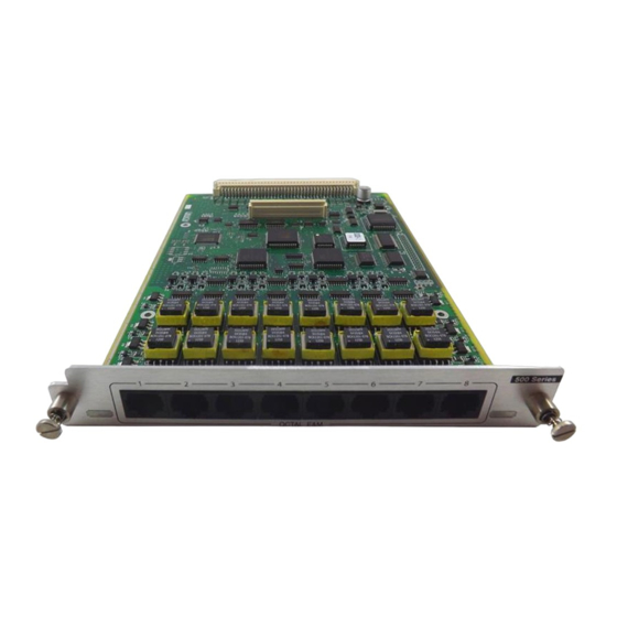
Chapter 1. Introduction Physical Description The Octal E&M Module plugs into any available option slot in the rear of the ATLAS 550 chassis. Figure 1-1 shows the Octal E&M Module. Figure 1-1. Octal E&M Module The labels over the modular connectors refer to the corresponding port on the Octal E&M Module. -
Page 13: Chapter 2 Installation
Carefully unpack and inspect the module for shipping damages. If you sus- pect damage occurred during shipping, file a claim immediately with the carrier and then contact ADTRAN Technical Support (see the last page of this manual for pertinent information). If possible, keep the original ship- ping container for returning the module for repair or for verification of ship- ping damage. -
Page 14: Installing The Octal E&M Module
Chapter 2. Installation INSTALLING THE OCTAL E&M MODULE Figure 2-1 shows how to install the module properly. The instructions are described in the Step/Action table, below. Remove Cover Plate Figure 2-1. Installing the Octal E&M Module Instructions for Installing the Octal E&M Module Step Action Remove the cover plate from the appropriate option slot in the... -
Page 15: Wiring
Chapter 2. Installation WIRING Each module port has a single 8-pin modular jack. A suitable mating connec- tor is AMP # 2-383021-5. The Octal E&M module is an E-lead originate sig- naling circuit suitable for connection to an M-lead originate trunk circuit. The pinout is shown in Table 2-1 and Table 2-2 Table 2-1. - Page 16 Chapter 2. Installation Octal E&M Module User Manual 61200313L1-1...
-
Page 17: Chapter 3 Operation
Operation Chapter 3 OVERVIEW The Octal E&M Module is controlled by the ATLAS 550 Base Unit terminal menu. The terminal menu allows for detailed configuration, status, and test- ing of the Octal E&M Module. Configuration of the Octal E&M Module is completed in two areas of the ter- minal menu: General configuration items for the Octal E&M-8 Voice Module are set using M... -
Page 18: Terminal Menu Structure
Chapter 3. Operation TERMINAL MENU STRUCTURE The ATLAS 550 uses a hierarchical menu structure to provide access to all of its features. The top-most menu level leads to submenus which are grouped by functionality. All menu items display in the terminal window. To access the Octal E&M Module, activate the M menu. -
Page 19: Slt
Chapter 3. Operation Part Number Serial Number Type Info Board Revision Assembly Revision Menu Alarm Port Status Status Modules Rx ABCD Tx ABCD Port Test 2W Test (Shortcut to Test) Test Tx ABCD 1kHz Tone State Port Loopback Port Name Configuration Sig lfce VF lfce... -
Page 20: Menu
Chapter 3. Operation Displays additional status and configuration menus for the selected module. To access the submenus for this item, use the arrow keys to scroll to the column for the module you want to edit, and press . For detailed Enter information on each submenu item, see the section Octal E&M Module Menu Options on page 3-5. -
Page 21: Offline
Chapter 3. Operation The module is installed, but has been taken offline by a user. The module is FFLINE still responding to controller polls. The module is installed, but has been taken offline by a user. The module is FFLINE not responding to polls. -
Page 22: Idle
Chapter 3. Operation Trunk not in use. Far end seizure. SSERTED Near end seizure. LEAD DETECTED Trunk in use. ALL IN ROGRESS Transmission Only mode. Force on-hook. Force off-hook. LOSED Generic test indicator. & T ABCD Receive and Transmit Signaling bits have local significance only, and repre- sent E&M signaling between the ATLAS 550 Controller and the voice port. -
Page 23: Tx Abcd
Chapter 3. Operation Table 3-1. Test 2W Information Test Module Output E-lead follows the Rx signaling bits E-lead Open Force on-hook E-lead Closed Force off-hook ABCD Forces the Transmit Robbed Bit Signaling (Tx RBS) to a specified value. Val- ues include O , 0000, 0101, 1010, or 1111. -
Page 24: Factory Restore
Chapter 3. Operation Selects signaling interface operation. The module supports all E&M types - I through V, as well as Transmission Only (TO) mode. Press-to-talk (PTT) mode is functionally identical to the E&M Type V mode. VF I Selects either 4-wire or 2-wire operation of the Voice Frequency (VF) Inter- face. -
Page 25: Appendix A Dial Plan Interface Configuration
Dial Plan Interface Configuration Appendix A INTERFACE CONFIGURATION The I option for the D menu (see Figure A-1) sets config- ONFIG uration parameters for the endpoint. These parameters vary by the type of port selected. The D menus are only accessible when using terminal mode. - Page 26 Appendix A. Dial Plan Interface Configuration OCTAL E&M MODULE INTERFACE CONFIGURATION The following sections describe U configuration settings for the Octal E&M Module when using the D menus. ORTS Read security: 5 Shows port allocation for the endpoint. The characters used to define the VAILABLE allocation have the following meanings: Describes available ports, as indicated by the displayed digit.
- Page 27 Appendix A. Dial Plan Interface Configuration XAMPLE A network port could be set to accept all calls beginning with 9 (9$), and then with S MSD set to 1, all digits would be sent toward the network TRIP except the leading 9. MSD does not affect C criteria.
- Page 28 Appendix A. Dial Plan Interface Configuration Octal E&M Module User Manual 61200313L1-1...
-
Page 29: Index
Index Numerics installing the module 2-1 Interface Configuration A-1 1kHz Tone 3-7 limited product warranty iv Alarm 3-4 Loopback 3-7 alarms 2-3 Analog 3-7 Assembly Revision 3-5 Digital 3-7 ATLAS 550 Features Used with Octal E&M Module 3-8 Off 3-7 Call in Progress 3-6 Menu 3-4 Caller ID Number A-2... - Page 30 Index Rx and Tx ABCD 3-6 Status (Status) 3-5 Rx Gain 3-8 Strip MSD A-2 self-test 3-8 terminal menu structure 3-2 failed 2-3 Test 3-4 Serial Number 3-5 Test 2W 3-6 service iv Test E-Lead Closed 3-6 Sig Ifce 3-8 Test E-Lead Open 3-6 Signaling Method A-2 testing, power-up 2-3...
- Page 31 Applications Engineering (800) 615-1176 Sales (800) 827-0807 Post-Sale Support Please contact your local distributor first. If your local distributor cannot help, please contact ADTRAN Technical Support and have the unit serial number available. Technical Support (888) 4ADTRAN Repair and Return If ADTRAN Technical Support determines that a repair is needed, Technical Support will coordinate with the Customer and Product Service (CAPS) department to issue an RMA number.
Need help?
Do you have a question about the Octal E&M and is the answer not in the manual?
Questions and answers