Advertisement
Quick Links
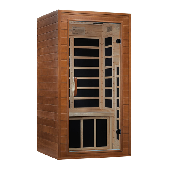
DYN-6103-01 / DYN-6203-01 / DYN-6203-02
1 & 2 Person FAR Infrared Sauna
Owner's Manual
INFRARED MODEL SAUNA
SAUNA IS FOR INDOOR USE ONLY
120VAC 15AMP Dedicated Circuit Required
Carefully and thoroughly read this Owner's Manual before using/operating the
sauna. We recommend keeping this Owner's Manual for regular review and
future reference.
1
Advertisement

Related Manuals for Dynamic Saunas DYN-6103-01


Summary of Contents for Dynamic Saunas DYN-6103-01
- Page 1 DYN-6103-01 / DYN-6203-01 / DYN-6203-02 1 & 2 Person FAR Infrared Sauna Owner’s Manual INFRARED MODEL SAUNA SAUNA IS FOR INDOOR USE ONLY 120VAC 15AMP Dedicated Circuit Required Carefully and thoroughly read this Owner’s Manual before using/operating the sauna. We recommend keeping this Owner’s Manual for regular review and...
- Page 2 TABLE OF CONTENTS Packing List Visual Assembly Diagrams Parts Description Assembly Instructions Operating the Sauna Tips for Using Your Sauna Safety Instructions Safeguards for Your Sauna Troubleshooting Guide Warranty Warranty Card WARNING: Visually inspect all heaters before assembly to make sure they are not damaged.
- Page 3 What Are Infrared Rays? Infrared is the band of light we perceive as heat. We cannot see this band of light with the naked eye, but we can feel this type of light in the form of heat. Our sun produces most of its energy output in the infrared segment of the spectrum.
- Page 4 5mG, and our Near Zero EMF models range at less than 3mG (NIR heaters range at about 5mG-7mG at the same approximate 2 inches). EMF Levels from Common Homes Sources After many years and numerous studies on EMF exposure, no government body including the Occupational Safety and Health Administration (OSHA) have established permissible exposure limits (PEL).
- Page 5 HOW IT WORKS Infrared Saunas differ from traditional saunas in that they use infrared radiant energy to directly penetrate into the body's tissue to produce perspiration. Traditional saunas use steam to heat the air inside the sauna, which then heats your body until you begin to perspire.
- Page 6 *PLEASE READ INSTRUCTIONS THOROUGHLY BEFORE ASSEMBLY* Visual Assembly Diagram DYN-6103-01 *THE ABOVE ASSEMBLY DIAGRAM IS FOR A QUICK REFERENCE VISUAL GUIDE ONLY. ALL SAUNA MODELS MAY NOT BE SHOWN. PARTS AND ACCESSORIES DO VARY AND ARE SUBJECT TO CHANGE.
- Page 7 *PLEASE READ INSTRUCTIONS THOROUGHLY BEFORE ASSEMBLY* Visual Assembly Diagram DYN-6203-01 *THE ABOVE ASSEMBLY DIAGRAM IS FOR A QUICK REFERENCE VISUAL GUIDE ONLY. ALL SAUNA MODELS MAY NOT BE SHOWN. PARTS AND ACCESSORIES DO VARY AND ARE SUBJECT TO CHANGE.
- Page 8 *PLEASE READ INSTRUCTIONS THOROUGHLY BEFORE ASSEMBLY* Visual Assembly Diagram DYN-6203-02 *THE ABOVE ASSEMBLY DIAGRAM IS FOR A QUICK REFERENCE VISUAL GUIDE ONLY. ALL SAUNA MODELS MAY NOT BE SHOWN. PARTS AND ACCESSORIES DO VARY AND ARE SUBJECT TO CHANGE.
- Page 9 *PLEASE READ INSTRUCTIONS THOROUGHLY BEFORE ASSEMBLY* PARTS DESCRIPTION *THE ABOVE ASSEMBLY DIAGRAM IS FOR A QUICK REFERENCE VISUAL GUIDE ONLY. ALL SAUNA MODELS MAY NOT BE SHOWN. MODEL DYN-6103-01 COMES WITH FAR INFRARED HEATERS. PARTS AND ACCESSORIES DO VARY AND ARE SUBJECT TO CHANGE.
- Page 10 *PLEASE READ INSTRUCTIONS THOROUGHLY BEFORE ASSEMBLY* PARTS DESCRIPTION *THE ABOVE ASSEMBLY DIAGRAM IS FOR A QUICK REFERENCE VISUAL GUIDE ONLY. ALL SAUNA MODELS MAY NOT BE SHOWN. MODEL DYN-6203-01 COMES WITH FAR INFRARED HEATERS. PARTS AND ACCESSORIES DO VARY AND ARE SUBJECT TO CHANGE.
- Page 11 *PLEASE READ INSTRUCTIONS THOROUGHLY BEFORE ASSEMBLY* PARTS DESCRIPTION *THE ABOVE ASSEMBLY DIAGRAM IS FOR A QUICK REFERENCE VISUAL GUIDE ONLY. ALL SAUNA MODELS MAY NOT BE SHOWN. MODEL DYN-6103-02 IS BASED ON FULL SPECTRUM TECHNOLOGY. PARTS AND ACCESSORIES DO VARY AND ARE SUBJECT TO CHANGE.
- Page 12 Power Supply The POWER SUPPLY is the control center of the sauna room. It is installed on the rooftop and has inputs/outputs connected to it. (see Figure 1) Figure 1 POWER IN - main power of the sauna room HT1, HT2, HT3, HT4, HT5, HT6 – heat emitter cords LAMPROOF –...
- Page 13 III. MP3 Auxiliary Port The MP3 Auxiliary Port allows you to connect a MP3 player or other device with the auxiliary function to the speakers in the sauna room for your listening pleasure. (see Figure 2) Figure 2 Buckles External Buckles The external buckles are used to connect the LEFT and RIGHT SIDE PANELS to the REAR PANEL.
- Page 14 Figure 4 Panel Descriptions For easier assembly, please understand and distinguish the differences between each panel. Floor Panel When the FLOOR PANEL faces upward, the surface will be flat. (see Figure 7) Understanding the Difference Between the Top and Bottom of the Wall Panels The (4) panels are in the upright position when the moldings are at the top.
- Page 15 Figure 6 Understanding the Difference Between the Inside and Outside of the Rear Panel You will find the heat emitters on the inside of the REAR PANEL. Assembly Instructions 1. Choose a good location to assembly the sauna The location must be dry, level, and away from any source of water. The dedicated outlet must be easily accessible.
- Page 16 Figure 7 3. Installing the FRONT PANEL with the LEFT SIDE PANEL with GLASS DOOR A. Place the FRONT PANEL up against the FLOOR PANEL as seen in Figure 8. There will be a molding at the bottom of the FRONT PANEL that will rest on the FLOOR PANEL.
- Page 17 Figure 11 5. Installing the REAR PANEL A. Place the REAR PANEL up against the FLOOR PANEL. There will be a molding at the bottom of the REAR PANEL that will rest on the FLOOR PANEL. You may need to open up the RIGHT SIDE PANEL and LEFT SIDE PANEL to fit the REAR PANEL between the two.
- Page 18 B. Plug in the BENCH HEAT EMITTER connector to the inlet on the REAR PANEL. C. Install the BENCH by sliding it over the horizontal bench guides on the side panels. Push the BENCH all the way in until it touches the REAR PANEL and is secured in place.
- Page 19 8. Installing the ROOF PANEL A. The side of the ROOF PANEL with the ceiling vent will be situated towards the rear of the sauna. Two adults can carefully lift the ROOF PANEL up and onto the top of the sauna room. Be careful when setting the ROOF PANEL into place as the cords and wire harness will need to be fed up to the topside of the ROOF PANEL.
- Page 20 TEMPERATURE SENSOR. Situate the TEMPERATURE SENSOR so that it is vertical and pointing downward. (see Figure 17) Figure 17 Please Note: Some sauna models are shipped with a spare TEMPERATURE SENSOR (inside the Accessory Box) in the case that the TEMPERATURE SENSOR is damaged during transit. The manufacturer decides this according to sauna models and packaging.
- Page 21 Operating the Sauna NOTE: Before the sauna is turned on, remove plastic protective covering from the CONTROL PANELS. Please check and confirm that the connections to the POWER SUPPLY (including the power cord), HEAT EMITTERS, CD/RADIO, and TEMPERATURE SENSOR are connected properly and are snug and tight. The power supply voltage and frequency must match the requested voltage and frequency of the sauna (120VAC 15AMP Dedicated Circuit or 120VAC 20AMP Dedicated Circuit).
- Page 22 1. Plug the sauna into the wall outlet. 2. Press the POWER button once. The POWER light will come on, the TIME DISPLAY will show 90 (minutes), the TEMPERATURE DISPLAY will show 151 F / 66 C, and the control panel will flash. 3.
- Page 23 panel. The white light will come on. While pointing the remote at the ceiling light, you can press any of the colors on the remote and that color will be displayed. You can use the SHADE button on the remote to go through a sequence of colors. If you want to turn the light off during your sauna session, you can press the POWER button on the remote.
- Page 24 Please keep in mind that you can either preheat the sauna to the set temperature before entering or sit inside the sauna as the temperature rises. In addition, you will increase the time it takes for the sauna to reach the set temperature if you enter the sauna room before it has reached the set temperature.
- Page 25 6. At the first sign of a cold or flu, increasing your sauna sessions may be beneficial in boosting your immune system and decreasing the reproductive rate of the virus. 7. To help relieve sore and tense muscles, massage the affected areas during your sauna session.
- Page 26 high blood pressure, circulatory system problems, diabetes, or other medical conditions should consult with a medical physician prior to using the sauna. 9. Persons using medications should consult with a medical physician before using the sauna. Some medications may induce drowsiness while other may affect the heart rate, blood pressure, and/or blood circulation.
- Page 27 operation. If for any reason your sauna does not seem to be operating properly, discontinue use and contact Customer Service. Safeguards For Your Sauna 1. Do not install the sauna near water, near a bathtub (if water will splash on the sauna), near a shower (if water will splash on the sauna), in a wet basement, or near a swimming pool (if water will splash on the sauna).
- Page 28 applicable). Go to the roof, and also check that the heat emitter cords are properly connected snug and tight to the cords on the roof and that those cords are properly plugged into the power supply (snug and tight). Solution: If some of the heat emitters are working, then the ones which are not working may have been damaged or are not properly connected.
- Page 29 control panel may have been damaged and will need to be replaced. Before contacting Customer Service, remove the wood frame holding the control panel in place to gain access to the “CTRL” connection behind the control panel. Once you remove the control panel from the wall panel, you can disconnect and reconnect the connection making sure it is snug and tight.
- Page 30 Step B: 1. Make sure to first unplug the sauna’s power cord from the wall outlet or power source. If the sauna is hard wired straight to the breaker in the Electric Panel, turn the breaker to the “OFF” position. 2.
- Page 31 7. Speaker Noise Solution: If you are hearing a humming noise from either speaker or both speakers while the Bluetooth feature is connected with your musical device, then there may be an issue with the control panel(s). To confirm this, please connect your musical device using the MP3 AUX wire that came with the sauna room to connect your musical device to the sauna speaker system.
- Page 32 and time to 90 minutes. Record the starting/beginning temperature and the temperature after 15 minute intervals up to 90 minutes (do not enter the unit or open the door during this test). If the sauna room goes above 130 degrees F (usually after about 40 to 50 minutes of preheating with a beginning temperature above 70 degrees F) at any given time, then we know that the heat emitters are working successfully.
- Page 33 Limited Lifetime Warranty 5 Year Limited Warranty: Golden Designs, Inc. under the Dynamic brand name warranties the wood, structure, heating elements, and electronics against defects in material and workmanship for a period of 1 to 5 years from the original date of purchase. This sauna is for INDOOR use only.
- Page 34 ▪ Use of product not in accordance with instructions ▪ Worn out receptacle Surface cracks are not considered defects in material or workmanship, as they are normal characteristics of all woods. This includes minor cracks due to wood expansion and contraction. Note: Since the wood used in construction has been kiln dried, a certain amount of expansion and contraction occurs in the wood in a sauna environment.
- Page 35 WARRANTY CARD Congratulations on your purchase of an Infrared Sauna from Golden Designs, Inc. Please take the time to complete the following Warranty Card and mail it back to: Golden Designs, Inc. 3550 Jurupa Street, Unit B Ontario, CA 91761 Please include a copy of your sales receipt showing date of purchase as this will serve as proof of purchase.
Need help?
Do you have a question about the DYN-6103-01 and is the answer not in the manual?
Questions and answers