Table of Contents
Advertisement
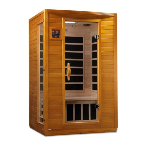
Infrared Sauna Instruction Manual
Models: DYN-6202-03 / DYN-6206-01
2 Person FAR Infrared Saunas
CARBON MODEL SAUNA
FOR INDOOR USE ONLY
120VAC 15AMP Dedicated Circuit Required
Carefully and thoroughly read this Owner's Manual before using/operating
the sauna. We recommend keeping this Owner's Manual for regular review
and future reference.
1
Advertisement
Table of Contents

Related Manuals for Dynamic Saunas DYN-6202-03


Summary of Contents for Dynamic Saunas DYN-6202-03
- Page 1 Infrared Sauna Instruction Manual Models: DYN-6202-03 / DYN-6206-01 2 Person FAR Infrared Saunas CARBON MODEL SAUNA FOR INDOOR USE ONLY 120VAC 15AMP Dedicated Circuit Required Carefully and thoroughly read this Owner’s Manual before using/operating the sauna. We recommend keeping this Owner’s Manual for regular review...
-
Page 2: Table Of Contents
TABLE OF CONTENTS Packing List Visual Assembly Diagrams Parts Description Assembly Instructions Operating the Sauna Tips for Using Your Sauna Safety Instructions Safeguards for Your Sauna Troubleshooting Guide Warranty Warranty Card WARNING: Visually inspect all heaters before assembly to make sure they are not damaged. - Page 3 What Are Infrared Rays? Infrared is the band of light we perceive as heat. We cannot see this band of light with the naked eye, but we can feel this type of light in the form of heat. Our sun produces most of its energy output in the infrared segment of the spectrum.
- Page 4 EMF Levels from Common Homes Sources After many years and numerous studies on EMF exposure, no government body including the Occupational Safety and Health Administration (OSHA) have established permissible exposure limits (PEL). Currently, there is no consensus on the potential health hazard from any exposure to EMF.
- Page 5 HOW IT WORKS Infrared Saunas differ from traditional saunas in that they use infrared radiant energy to directly penetrate into the body's tissue to produce perspiration. Traditional saunas use steam to heat the air inside the sauna, which then heats your body until you begin to perspire.
-
Page 6: Visual Assembly Diagrams
*PLEASE READ INSTRUCTIONS BEFORE ASSEMBLY* Visual Assembly Diagram DYN-6202-03 *The above assembly diagram i s for a quick reference visual guide only. All sauna models are not shown. Parts and accessories may vary and are subject to change. Backrests are sold separately. We have found that starting the assembly process with the floor and front wall panel first may be the easiest, but it is not mandatory. - Page 7 *PLEASE READ INSTRUCTIONS BEFORE ASSEMBLY* Visual Assembly Diagram DYN-6206-01 *The above assembly diagram i s for a quick reference visual guide only. All sauna models are not shown. Parts and accessories may vary and are subject to change. Backrests are sold separately. We have found that starting the assembly process with the floor and front wall panel first may be the easiest, but it is not mandatory.
-
Page 8: Parts Description
PARTS DESCRIPTION DYN-6202-03 NOTE: The pictures and diagrams shown within this owner’s manual are representations of this model. Actual model may vary. Design and Construction are subject to change. Backrests are sold separately. - Page 9 PARTS DESCRIPTION DYN-6206-01 NOTE: The pictures and diagrams shown within this owner’s manual are representations of this model. Actual model may vary. Design and Construction are subject to change. Backrests are sold separately.
- Page 10 Highlights Power Supply (Control Box) The POWER SUPPLY is the control center of the sauna room. It is installed on the topside of the ROOF PANEL and has inputs/outputs connected to it. (see Figure 1) Figure 1 POWER IN - main power of the sauna room HT1, HT2, HT3, HT4, HT5, HT6 –...
- Page 11 III. MP3 Auxiliary Port The MP3 Auxiliary Port allows you to connect a MP3 player or other device with the auxiliary function to the speakers in the sauna room for your listening pleasure. (see Figure 2) Figure 2 Buckles External Buckles The external buckles are used to connect the LEFT and RIGHT SIDE PANELS to the REAR PANEL.
- Page 12 Panel Descriptions For easier assembly, please understand and distinguish the differences between each panel. Floor Panel When you place the FLOOR PANEL at its designated location, be sure to leave enough space so that you are able to move around the FLOOR PANEL during the assembly process.
-
Page 13: Assembly Instructions
Assembly Instructions A. Choose a good location to install the sauna 1. The location must be dry, leveled, and away from any source of water 2. MAIN POWER cord must be easily accessible 3. Two adults are required for installation 4. - Page 14 C. Installing the FRONT PANEL and SIDE PANELS 1. Place the FRONT PANEL onto the recessed area on the FLOOR PANEL. Align the FRONT PANEL with the guide on the FLOOR PANEL. The RIGHT SIDE PANEL will need to be lifted in order to lock the guide inserts on the FRONT PANEL into the guides on the RIGHT SIDE PANEL.
- Page 15 Installing the BENCH HEAT EMITTER PANEL and BENCH 1. To install the BENCH HEAT EMITTER PANEL, you will need to slide the BENCH HEAT EMITTER PANEL into place as indicated in the pictures below. The BENCH and BENCH HEAT EMITTER PANEL do vary in installation and design.
- Page 16 Owner’s Manual can be used to mount the ROOF PANEL to each of the wall panels. Screwing the ROOF PANEL down is optional. G. Connecting the plugs on the ROOF PANEL 1. Connect the plugs according to the respective labels. (see Figure 12 & 13) 2.
- Page 17 1. Place the ROOF COVER over the top of the sauna. Be cautious when pulling the power cord through the hole in the roof cover. Gently place the ROOF COVER onto the ROOF PANEL. When the edges are aligned, screw the ROOF COVER to the roof panel. (see figure 15) Figure 15 J.
-
Page 18: Operating The Sauna
Operating the Sauna NOTE: Before the sauna is turned on, remove plastic protective covering from the CONTROL PANELS. Please check and confirm that the connections to the POWER SUPPLY (including the power cord), HEAT EMITTERS, CD/RADIO, and TEMPERATURE SENSOR are connected properly and are snug and tight. The power supply voltage and frequency must match the requested voltage and frequency of the sauna (120VAC 15AMP Dedicated Circuit or 120VAC 20AMP Dedicated Circuit). - Page 19 2. Press the POWER button once. The POWER light will come on, the TIME DISPLAY will show 90 (minutes), the TEMPERATURE DISPLAY will show 151 F / 66 C, and the control panel will flash. 3. Press the up/down arrows under the TIME DISPLAY to adjust the amount of time you want the sauna to remain on.
- Page 20 use the SHADE button on the remote to go through a sequence of colors. If you want to turn the light off during your sauna session, you can press the POWER button on the remote. Please note: You must be inside the sauna room for the remote to work.
-
Page 21: Tips For Using Your Sauna
Please keep in mind that you can either preheat the sauna to the set temperature before entering or sit inside the sauna as the temperature rises. In addition, you will increase the time it takes for the sauna to reach the set temperature if you enter the sauna room before it has reached the set temperature. -
Page 22: Safety Instructions
your legs to trap the heat. 5. This is a non-commercial sauna. For every three hours ON, the sauna must be turned OFF for one hour to cool down. 6. At the first sign of a cold or flu, increasing your sauna sessions may be beneficial in boosting your immune system and decreasing the reproductive rate of the virus. - Page 23 7. The use of alcohol, drugs, or medications (prescribed or non-prescribed) prior to or during the sauna session may lead to unconsciousness and/or other harmful physical injuries. 8. Persons suffering from obesity or with a medical history of heart disease, low or high blood pressure, circulatory system problems, diabetes, or other medical conditions should consult with a medical physician prior to using the sauna.
-
Page 24: Safeguards For Your Sauna
23. Do not make any modifications to the sauna, the sauna structure, or the sauna components. 24. Prior to each sauna session, the sauna room is to be inspected for correct operation. If for any reason your sauna does not seem to be operating properly, discontinue use and contact Customer Service. - Page 25 Troubleshooting Before any troubleshooting of the sauna, make sure to unplug the sauna’s power cord from the wall outlet. If the sauna is hard wired straight to the breaker in the Electric Panel, turn the breaker to the “OFF” position. 1.
- Page 26 buttons are now responding. Contact the Customer Service for any additional troubleshooting. Solution: If the control panel is showing no signs of power, then there could be a connection issue of the “CTRL” harness behind the control panel. You will need to remove the wood frame holding the control panel in place to gain access to the “CTRL”...
- Page 27 Solution: If your control panel displays “-L”, it may be an error code and we assume both control panels are displaying this. If so, then it means there is a communication issue between the control panel, power supply, and temperature sensor. Please proceed to the following: Step A: 1.
- Page 28 fine in the beginning when supplying power to the sauna and then suddenly starts causing problems for the sauna power supply. We recommended not connecting the sauna power cord to a GFCI protected outlet. 5. Wall Outlet Melting Solution: A common problem with wall outlets is loose wiring on the connection points of the terminals of the receptacle.
- Page 29 tight. Return back to the sauna control panel to test the light. If the light is still having issues, please contact our Customer Service. 9. Dedicated Power Outlet Solution: You have two options when it comes to a dedicate receptacle. You have a true dedicated line if the receptacle is the only receptacle on the line to the breaker in your electric panel box.
- Page 30 11. Intentional Rear Wall Warp Solution: The rear wall panel is intentionally warped as part of the sauna design. This adds strength to the sauna structure once the unit is assembled. Please try the following in assembling the sauna. With one person inside the sauna room and pushing on the rear wall panel outward, a second person should be able to latch the buckles.
- Page 31 Limited Lifetime Warranty 5 Year Limited Warranty: Golden Designs, Inc. under the Dynamic brand name warranties the wood, structure, heating elements, and electronics against defects in material and workmanship for a period of 1 to 5 years from the original date of purchase. This sauna is for INDOOR use only.
-
Page 32: Warranty
Outdoor applications Normal wear and tear or weathering Use of product not in accordance with instructions Worn out receptacle Surface cracks are not considered defects in material or workmanship, as they are normal characteristics of all woods. This includes minor cracks due to wood expansion and contraction. -
Page 33: Warranty Card
WARRANTY CARD Congratulations on your purchase of an Infrared Sauna from Golden Designs, Inc. Please take the time to complete the following Warranty Card and mail it back to: Golden Designs, Inc. 3550 Jurupa Street, Unit B Ontario, CA 91761 Please include a copy of your sales receipt showing date of purchase as this will serve as proof of purchase.
Need help?
Do you have a question about the DYN-6202-03 and is the answer not in the manual?
Questions and answers