Advertisement
Quick Links
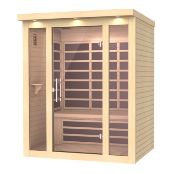
Infrared Sauna Instruction Manual
Models: DYN-6215-02 / DYN-6315-02
2 & 3 Person FAR Infrared Saunas
CARBON MODEL SAUNA
FOR INDOOR USE ONLY
120VAC 15AMP Dedicated Circuit Required (2 Person Models)
120VAC 20AMP Dedicated Circuit Required (3 Person Models)
Carefully and thoroughly read this Owner's Manual before using/operating the
sauna. We recommend keeping this Owner's Manual for regular review and
future reference.
1
Advertisement

Related Manuals for Dynamic Saunas DYN-6315-02


Summary of Contents for Dynamic Saunas DYN-6315-02
- Page 1 Infrared Sauna Instruction Manual Models: DYN-6215-02 / DYN-6315-02 2 & 3 Person FAR Infrared Saunas CARBON MODEL SAUNA FOR INDOOR USE ONLY 120VAC 15AMP Dedicated Circuit Required (2 Person Models) 120VAC 20AMP Dedicated Circuit Required (3 Person Models) Carefully and thoroughly read this Owner’s Manual before using/operating the sauna.
-
Page 2: Table Of Contents
TABLE OF CONTENTS Packing List Visual Assembly Diagrams Parts Description Assembly Instructions Operating the Sauna Tips for Using Your Sauna Safety Instructions Safeguards for Your Sauna Troubleshooting Guide Warranty Warranty Card WARNING: Visually inspect all heaters before assembly to make sure they are not damaged. - Page 3 What Are Infrared Rays? Infrared is the band of light we perceive as heat. We cannot see this band of light with the naked eye, but we can feel this type of light in the form of heat. Our sun produces most of its energy output in the infrared segment of the spectrum.
- Page 4 EMF Levels from Common Homes Sources After many years and numerous studies on EMF exposure, no government body including the Occupational Safety and Health Administration (OSHA) have established permissible exposure limits (PEL). Currently, there is no consensus on the potential health hazard from any exposure to EMF.
- Page 5 HOW IT WORKS Infrared Saunas differ from traditional saunas in that they use infrared radiant energy to directly penetrate into the body's tissue to produce perspiration. Traditional saunas use steam to heat the air inside the sauna, which then heats your body until you begin to perspire.
-
Page 6: Visual Assembly Diagrams
*PLEASE READ INSTRUCTIONS BEFORE ASSEMBLY* Visual Assembly Diagram DYN-6215-02 *The above assembly diagram i s for a quick reference visual guide only. All sauna models are not shown. Parts and accessories may vary and are subject to change. Backrests are sold separately. - Page 7 *PLEASE READ INSTRUCTIONS BEFORE ASSEMBLY* Visual Assembly Diagram DYN-6315-02 *The above assembly diagram i s for a quick reference visual guide only. All sauna models are not shown. Parts and accessories may vary and are subject to change. Backrests are sold separately.
-
Page 8: Parts Description
PARTS DESCRIPTION DYN-6215-02 NOTE: The pictures and diagrams shown within this owner’s manual are representations of this model. Actual model may vary. Design and Construction are subject to change. Backrests are sold separately. - Page 9 PARTS DESCRIPTION DYN-6315-02 NOTE: The pictures and diagrams shown within this owner’s manual are representations of this model. Actual model may vary. Design and Construction are subject to change. Backrests are sold separately.
- Page 10 Highlights Power Supply (Control Box) The POWER SUPPLY is the control center of the sauna room. It is installed on the topside of the ROOF PANEL and has inputs/outputs connected to it. (see Figure 1) Figure 1 POWER IN - main power of the sauna room HT1, HT2, HT3, HT4, HT5, HT6 –...
- Page 11 III. MP3 Auxiliary Port The MP3 Auxiliary Port allows you to connect a MP3 player or other device with the auxiliary function to the speakers in the sauna room for your listening pleasure. (see Figure 2) Figure 2 Buckles External Buckles The external buckles are used to connect the LEFT and RIGHT SIDE PANELS to the REAR PANEL.
- Page 12 Panel Descriptions For easier assembly, please understand and distinguish the differences between each panel. Floor Panel When the FLOOR PANEL faces upward, you will find the floor heat emitter(s) on the topside of the FLOOR PANEL. The heater cord will be towards the rear.
- Page 13 Assembly Please note the following: A. You will need a Philips screwdriver, ladder, and two adults to assemble. B. Do not plug any other appliances into the power supply of the sauna room other than the designated sauna connections/plugs. C. Assemble the sauna room on a completely level surface. D.
- Page 14 Figure 8 3. Installing the REAR PANEL A. Remove the protection paper from the buckles on the REAR WALL PANEL. Place the REAR WALL PANEL up against the FLOOR PANEL with the ¼ round molding resting on the FLOOR PANEL. Next, attach the REAR WALL PANEL to the RIGHT SIDE WALL PANEL and use the buckles to latch together.
- Page 15 4. Installing the BENCH HEAT EMITTER PANEL and BENCH A. Installing the BENCH HEAT EMITTER PANEL can be a little tricky. You will need to slide the BENCH HEAT EMITTER PANEL down evenly into place as indicated in the pictures below. (see Figure 10) B.
- Page 16 5. Installing the FRONT GLASS DOOR HANDLE A. Now that the FRONT WALL PANEL has already been installed, the inner and outer door handles need to be mounted to the FRONT GLASS DOOR. According to Figure 11 and Figure 12, the FRONT GLASS DOOR must sit between the (2) white washers.
- Page 17 6. Installing the ROOF PANEL A. The side of the ROOF PANEL with the power supply (control box) is the top of the ROOF PANEL. B. The edge nearest the power supply is the front of the ROOF PANEL. Be careful of the wires coming from the SIDE and REAR PANELS when you set the ROOF PANEL down onto the panels.
- Page 18 Before Connecting Figure 15 After Connecting Figure 16 8. Installing the TEMPERATURE SENSOR and Optional MAGAZINE RACK/TOWEL RACK A. Enter the sauna and remove the protective covering (masking tape) from the TEMPERATURE SENSOR. Situate the TEMPERATURE SENSOR so that it is vertical and pointing downward.
- Page 19 Figure 17 Note: Some sauna models are shipped with a spare TEMPERATURE SENSOR in case the TEMPERATURE SENSOR is damaged during transit. The manufacturer decides this according to sauna models and packaging. B. If your sauna comes with the optional MP3 shelf, magazine rack, cup holder shelf, or towel rack, use the provided screws and mount according to designated labeled locations.
-
Page 20: Operating The Sauna
Operating the Sauna Control Panel Power On/Off: Press to control the main power of the sauna Power Indicator: Indicates the status of the sauna’s main power Work Start/Stop: Press to control the working functions of the sauna Work Indicator: Indicates the working status of the sauna Heat Indicator: Indicates the status of heating function Light: Press to control the lighting function Time Display: Displays the heating time of the sauna in minutes... - Page 21 degrees Fahrenheit / 48 degrees Celsius. When the ambient temperature is low, heating requires additional time. For the first few times of use, you may use 115 degrees Fahrenheit / 46 degrees Celsius as a reference starting point for a time period of about 20 to 30 minutes (this represents the actual time you are in the sauna at the desired temperature).
- Page 22 10. The MP3 Jack will allow you to connect your musical device using the AUX wire. Plug one end of the AUX wire into your musical device and the other end into the MP3 Jack at the ceiling. Do not leave the AUX wire connected at the ceiling when not using this function as it may cause static interference at the speakers.
-
Page 23: Tips For Using Your Sauna
Tips for using Your Sauna 1. If you take a hot/warm shower or bath before using your sauna, you may perspire more and experience more comfort. 2. Drink water prior to, during, and after your sauna session to replenish body fluids. 3. - Page 24 4. Do not use the sauna immediately following strenuous exercises. Wait at least 30 minutes to allow the body to cool down completely. 5. Pregnant or possibly pregnant women should contact their medical physician prior to using the sauna. Excessive temperatures have a high potential for causing fetal harm during pregnancy.
-
Page 25: Safeguards For Your Sauna
sauna with wet hands or wet feet to avoid the risk of electrical shock or injury. Never touch the metal prongs of the plug. 19. Do not attempt to make any repairs yourself unless authorized by the manufacturer or its agent. If a problem occurs with the sauna, please contact the manufacturer or its agent immediately to avoid safety risks. - Page 26 Troubleshooting Before any troubleshooting of the sauna, make sure to unplug the sauna’s power cord from the wall outlet. If the sauna is hard wired straight to the breaker in the Electric Panel, turn the breaker to the “OFF” position. 1.
- Page 27 buttons are now responding. Contact the Customer Service for any additional troubleshooting. Solution: If the control panel is showing no signs of power, then there could be a connection issue of the “CTRL” harness behind the control panel. You will need to remove the wood frame holding the control panel in place to gain access to the “CTRL”...
- Page 28 Solution: If your control panel displays “-L”, it may be an error code and we assume both control panels are displaying this. If so, then it means there is a communication issue between the control panel, power supply, and temperature sensor. Please proceed to the following: Step A: 1.
- Page 29 fine in the beginning when supplying power to the sauna and then suddenly starts causing problems for the sauna power supply. We recommended not connecting the sauna power cord to a GFCI protected outlet. 5. Wall Outlet Melting Solution: A common problem with wall outlets is loose wiring on the connection points of the terminals of the receptacle.
- Page 30 tight. Return back to the sauna control panel to test the light. If the light is still having issues, please contact our Customer Service. 9. Dedicated Power Outlet Solution: You have two options when it comes to a dedicate receptacle. You have a true dedicated line if the receptacle is the only receptacle on the line to the breaker in your electric panel box.
- Page 31 11. Intentional Rear Wall Warp Solution: The rear wall panel is intentionally warped as part of the sauna design. This adds strength to the sauna structure once the unit is assembled. Please try the following in assembling the sauna. With one person inside the sauna room and pushing on the rear wall panel outward, a second person should be able to latch the buckles.
- Page 32 Limited Lifetime Warranty 5 Year Limited Warranty: Golden Designs, Inc. under the Dynamic brand name warranties the wood, structure, heating elements, and electronics against defects in material and workmanship for a period of 1 to 5 years from the original date of purchase. This sauna is for INDOOR use only.
-
Page 33: Warranty
Outdoor applications Normal wear and tear or weathering Use of product not in accordance with instructions Worn out receptacle Surface cracks are not considered defects in material or workmanship, as they are normal characteristics of all woods. This includes minor cracks due to wood expansion and contraction. - Page 34 PAGE INTENTIONALLY LEFT BLANK...
-
Page 35: Warranty Card
WARRANTY CARD Congratulations on your purchase of an Infrared Sauna from Golden Designs, Inc. Please take the time to complete the following Warranty Card and mail it back to: Golden Designs, Inc. 3550 Jurupa Street, Unit B Ontario, CA 91761 Please include a copy of your sales receipt showing date of purchase as this will serve as proof of purchase.
Need help?
Do you have a question about the DYN-6315-02 and is the answer not in the manual?
Questions and answers