Table of Contents
Advertisement
Quick Links
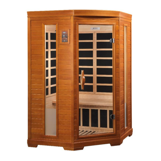
DYN-6225-02
2 Person FAR Infrared Corner Sauna
Owner's Manual
CARBON MODEL SAUNA
SAUNA IS FOR INDOOR USE ONLY
120VAC 15AMP Dedicated Circuit Required
Carefully and thoroughly read this Owner's Manual before using/operating the
sauna. We recommend keeping this Owner's Manual for regular review and
future reference.
Advertisement
Table of Contents

Related Manuals for Dynamic Saunas DYN-6225-02


Summary of Contents for Dynamic Saunas DYN-6225-02
- Page 1 DYN-6225-02 2 Person FAR Infrared Corner Sauna Owner’s Manual CARBON MODEL SAUNA SAUNA IS FOR INDOOR USE ONLY 120VAC 15AMP Dedicated Circuit Required Carefully and thoroughly read this Owner’s Manual before using/operating the sauna. We recommend keeping this Owner’s Manual for regular review and...
- Page 2 What Are Infrared Rays? Infrared is the band of light we perceive as heat. We cannot see this band of light with the naked eye, but we can feel this type of light in the form of heat. Our sun produces most of its energy output in the infrared segment of the spectrum.
- Page 3 Health Benefits Include, But Are Not Limited To: *Pain relief from Rheumatoid Arthritis *Relaxes muscle spasms *Increases blood circulation *Cardiovascular conditioning *Clears rashes, acne *Reduces cellulite *Removes toxins and mineral waste *Reduces stress and fatigue *Enhances skin tone DISCLAIMER The infrared rays emitted by your sauna are reported to offer a wide range of possible therapeutic benefits based on research completed over the last 40 years from all around the world.
- Page 4 as “power frequency” fields. Hertz is the unit for measuring the frequency of fields in the number of wave cycles each second. The lower the frequency of a field, the lower its energy. Power frequency fields are low frequency fields and have low energy levels. Microwave and x-ray fields are high frequency fields and have high energy levels.
- Page 5 *PLEASE READ INSTRUCTIONS THOROUGHLY BEFORE ASSEMBLY* DYN-6225-02 *THE ABOVE ASSEMBLY DIAGRAM IS FOR A QUICK REFERENCE VISUAL GUIDE ONLY. ALL SAUNA MODELS MAY NOT BE SHOWN. PARTS AND ACCESSORIES DO VARY AND ARE SUBJECT TO CHANGE. Page 4...
-
Page 6: Table Of Contents
TABLE OF CONTENTS Product Introduction Parts Description Assembly Instructions Operating the Sauna Tips for Using your Sauna Safety Instructions Safeguards for your Sauna Troubleshooting Guide Warranty Warranty Card WARNING: Visually inspect all heaters before assembly to make sure they are not damaged. -
Page 7: Parts Description
*PLEASE READ INSTRUCTIONS THOROUGHLY BEFORE ASSEMBLY* PARTS DESCRIPTION *THE ABOVE ASSEMBLY DIAGRAM IS FOR A QUICK REFERENCE VISUAL GUIDE ONLY. ALL SAUNA MODELS MAY NOT BE SHOWN. PARTS AND ACCESSORIES DO VARY AND ARE SUBJECT TO CHANGE. Page 6... - Page 8 Power Supply (Control Box) The POWER SUPPLY is the control center of the sauna room. It is installed on the topside of the ROOF PANEL and has inputs/outputs connected to it. (see Figure 1) Figure 1 POWER IN - main power of the sauna room HT1, HT2, HT3, HT4, HT5, HT6 –...
- Page 9 III. MP3 Auxiliary Port The MP3 Auxiliary Port allows you to connect a MP3 player or other device with the auxiliary function to the speakers in the sauna room for your listening pleasure. (see Figure 2) Figure 2 Buckles External Buckles The external buckles are used to connect the LEFT and RIGHT SIDE PANELS to the REAR PANEL.
- Page 10 Figure 4 Radio The multifunction FM radio features a large LCD screen, volume/mode/balance controls, and AUX/USB/SD. (see Figure 5) Figure 5 Panel Descriptions For easier assembly, please understand and distinguish the differences between each panel. Floor Panel When the FLOOR PANEL faces upward, you will find the floor heat emitter(s) on the topside of the FLOOR PANEL.
- Page 11 Understanding the Difference Between the Top and Bottom of the Wall Panels The (4) panels are in the upright position when the heat emitter panels are closer to the top of the wall panel than the bottom of the wall panel.
-
Page 12: Assembly Instructions
Understanding the Difference Between the Inside and Outside of the Rear Panel You will find the heat emitters on the interior of the REAR PANEL. (see Figure 9) Figure 9 Assembly Instructions 1. Choose a good location to assembly the sauna The location must be dry, level, and away from any source of water. - Page 13 Front Wood Braces Figure 10 Figure 10a 3. Installing the RIGHT SIDE REAR PANEL and LEFT SIDE REAR PANEL A. Remove the protection paper (tape) from the external buckles. Place the RIGHT SIDE REAR PANEL up and onto the FLOOR PANEL. While one adult is holding the RIGHT SIDE REAR PANEL in place, the second adult can place the LEFT SIDE REAR PANEL up and onto the FLOOR PANEL.
- Page 14 Figure 12 Figure 13 5. Installing the FRONT PANEL A. Place the FRONT PANEL onto the recessed area on the FLOOR PANEL. Align guide and guide inserts on the LEFT SIDE PANEL with those on the FRONT PANEL. The LEFT SIDE PANEL will need to be lifted in order to lock the guide inserts on the LEFT SIDE PANEL into the guides on the FRONT PANEL.
- Page 15 6. Installing the ROOF PANEL A. The side with the power supply box faces upward. B. The edge nearest the power supply is the front of the ROOF PANEL. Be careful of the wires coming from the SIDE and REAR PANELS when you set the ROOF PANEL down onto the panels.
- Page 16 D. Install the BENCH by placing it on the top of the BENCH EMITTER PANEL and sliding it back towards the RIGHT SIDE REAR PANEL. Please note that the side with the predrilled holes will slide in first towards the RIGHT SIDE REAR PANEL.
- Page 17 9. Installing RADIO HOUSING BOX and RADIO (radio model subject to change) A. If your RADIO HOUSING BOX is already assembled, then proceed to step D. Locate the wood sides for the RADIO HOUSING BOX. There is one for the front, side, and bottom.
- Page 18 Figure 25 Figure 26 Installing the TEMPERATURE SENSOR A. Enter the sauna and remove the masking tape (if present) from the TEMPERATURE SENSOR. Situate the TEMPERATURE SENSOR so that it is vertical and pointing downward. (see Figure 27) Figure 27 Please Note: Some sauna models are shipped with a spare TEMPERATURE SENSOR (inside the Accessory Box) in the case that the TEMPERATURE SENSOR is damaged during transit.
-
Page 19: Operating The Sauna
Operating the Sauna NOTE: Before the sauna is turned on, remove plastic protective covering from the CONTROL PANELS. Please check and confirm that the connections to the POWER SUPPLY (including the power cord), HEAT EMITTERS, CD/RADIO, and TEMPERATURE SENSOR are connected properly and are snug and tight. The power supply voltage and frequency must match the requested voltage and frequency of the sauna (120VAC 20AMP Dedicated Circuit). - Page 20 1. Plug the sauna into the wall outlet. 2. Press the POWER button once. The POWER light will come on, the TIME DISPLAY will show 90 (minutes), the TEMPERATURE DISPLAY will show 151 F / 66 C, and the control panel will flash. 3.
- Page 21 color therapy lighting system . Press the READING LIGHT button on the sauna control panel. The white light will come on. While pointing the remote at the ceiling light, you can press any of the colors on the remote and that color will be displayed. You can use the SHADE button on the remote to go through a sequence of colors.
-
Page 22: Tips For Using Your Sauna
Tips for using Your Sauna 1. If you take a hot/warm shower or bath before using your sauna, you may perspire more and experience more comfort. 2. Drink water prior to, during, and after your sauna session to replenish body fluids. 3. - Page 23 5. Pregnant or possibly pregnant women should contact their medical physician prior to using the sauna. Excessive temperatures have a high potential for causing fetal harm during pregnancy. 6. Hyperthermia Danger: The normal body temperature can’t rise above 103°F (39°C). Symptoms of excessive hyperthermia include dizziness, lethargy, drowsiness, and/or fainting.
-
Page 24: Safeguards For Your Sauna
or its agent. If a problem occurs with the sauna, please contact the manufacturer or its agent immediately to avoid safety risks. Unauthorized repair attempts will void the manufacturer’s warranty. 20. Please make sure the outlet power supply meets the specifications required. Failure to meet the requirements may cause safety risks. -
Page 25: Troubleshooting Guide
Troubleshooting Before any troubleshooting of the sauna, make sure to unplug the sauna’s power cord from the wall outlet. If the sauna is hard wired straight to the breaker in the Electric Panel, turn the breaker to the “OFF” position. 1. - Page 26 4. Control Panel Malfunctioning Solution: If the control panel is showing no signs of power, then there could be a connection issue of the “CTRL” harness up on the roof. Go up to the roof and locate the “CTRL” wire harness you connected when the roof was installed onto the sauna room.
- Page 27 towards the rear of the sauna. After you have located the red and black wires labeled “TEMP SENSOR”, disconnect them. Connect the spare temperature sensor. For testing purposes, insert the “TEMP SENSOR” (you just connected) down the vent on the roof so that it is now inside the sauna. Then go to the control panel and press the power button.
- Page 28 connection is snug and tight. Leave the control panel hanging from the wall panel (do not replace with the wood frame as of yet). 4. Next, you can plug the sauna room back into the wall outlet or turn the breaker back “ON”.
- Page 29 Solution: If you hear static noises from the speakers when no music is playing, then be sure that the MP3 AUX wire is not plugged into the ceiling port. You will have a constant noise coming from the speakers if one end of the MP3 AUX wire is connected to the ceiling port and the other end is not connected to anything.
- Page 30 already removed). If you touch the heat emitter panel and it is warm-to-hot, then it is working correctly. If you are able to place your hand on the back side of the heat emitter and it feels like there is no heat being produced, then we know it is not working properly and you will need to contact Customer Service.
-
Page 31: Warranty
Limited Lifetime Warranty 5 Year Limited Warranty: Golden Designs, Inc. warranties the wood, structure, heating elements, and electronics against defects in material and workmanship for a period of 1 to 5 years from the original date of purchase. This sauna is for INDOOR use only. Placing your sauna outdoors will VOID this warranty. - Page 32 PAGE INTENTIONALLY LEFT BLANK Page 31...
-
Page 33: Warranty Card
WARRANTY CARD Congratulations on your purchase of an Infrared Sauna from Golden Designs, Inc. Please take the time to complete the following Warranty Card and mail it back to: Golden Designs, Inc. 3550 Jurupa Street, Unit B Ontario, CA 91761 Please include a copy of your sales receipt showing date of purchase as this will serve as proof of purchase.
Need help?
Do you have a question about the DYN-6225-02 and is the answer not in the manual?
Questions and answers