Table of Contents
Advertisement
Quick Links
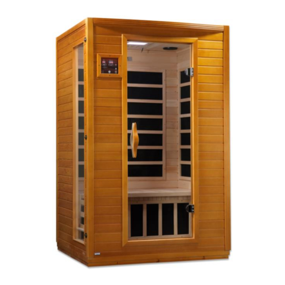
DYN6202 / DYN6232 / DYN6444
2 ‐ 4 Person Sauna
OWNER'S MANUAL
FOR CERAMIC AND CARBON MODEL SAUNAS
FOR INDOOR USE ONLY
120VAC 15 AMP (2-PERSON MODELS) DEDICATED CIRCUIT
120VAC 20 AMP (3 & 4 PERSON MODELS) DEDICATED CIRCUIT
Sauna: Now you can enjoy the European secret for youthful vitality.
Carefully and thoroughly read this manual before using the sauna. We
recommend keeping this manual for regular review and future reference.
Advertisement
Table of Contents

Related Manuals for Dynamic Saunas DYN6232


Summary of Contents for Dynamic Saunas DYN6232
- Page 1 DYN6202 / DYN6232 / DYN6444 2 ‐ 4 Person Sauna OWNER’S MANUAL FOR CERAMIC AND CARBON MODEL SAUNAS FOR INDOOR USE ONLY 120VAC 15 AMP (2-PERSON MODELS) DEDICATED CIRCUIT 120VAC 20 AMP (3 & 4 PERSON MODELS) DEDICATED CIRCUIT Sauna: Now you can enjoy the European secret for youthful vitality.
- Page 2 *PLEASE READ INSTRUCTIONS B E F O R E ASSEMBLY* The above assembly diagram is a quick reference visual example of the assembly process only. All sauna models are not shown. Model types, parts, and accessories may vary.
- Page 3 WHAT ARE INFRARED RAYS? Infrared is the band of light we perceive as heat. We cannot see this band of light with the naked eye, but we can feel this type of light in the form of heat. Our sun produces most of its energy output in the infrared segment of the spectrum.
- Page 4 HOW IT WORKS Infrared Saunas differ from traditional saunas in that they use infrared radiant energy to directly penetrate into the body's tissue to produce perspiration. Traditional saunas use steam to heat the air inside the sauna, which then heats your body until you begin to perspire.
- Page 5 Benefits include, but are not limited to: - Pain relief from Rheumatoid Arthritis - Relaxing muscle spasms - Increasing blood circulation - Cardiovascular conditioning - Clears rashes, acne - Reduces cellulite - Removes toxins and mineral waste - Reduces stress and fatigue - Enhances skin tone SAUNA MAINTENANCE Since infrared saunas do not require hot rocks, water, or steam to operate, they require very little...
-
Page 6: Table Of Contents
TABLE OF CONTENTS Product Introduction Parts Description Assembly Instructions Operating the Sauna Tips for Using Your Sauna Safety Instructions Safeguards for Your Sauna Troubleshooting Guide Warranty Warranty Card WARNING: Visually inspect all heaters before assembly to make sure they are not damaged. Any excessive vibrations during transport could cause damage to the heating elements. -
Page 7: Parts Description
PARTS DESCRIPTION A.FRONT OF SAUNA (see figure 1) B.INSIDE OF SAUNA (see figure 2) Figure 1 Figure 2 1) Control Panel 2) Door Handle 3) Tempered Glass Door 4) Speaker 5) Temperature Sensor 6) Ventilation Grid 7) Back Protection Grid 8) MP3 Auxiliary Socket (optional) - Page 8 I. Power Supply The POWER SUPPLY BOX is the control center of the sauna room. It is installed on the ROOF PANEL and has input/outputs connected to it as seen below. (see figure 3) Figure 3 MAIN POWER main power of the sauna room HT1, HT2, HT3, HT4 emitter power output cords LIGHT...
- Page 9 III. Component Labeling POWER Power Cord HT1, HT2, HT3, HT4 Emitter (heater) power cords LIGHT Reading lamp connector CTRL Control panel connector CD/SIG For CD/temperature sensor/buzzer/etc. connectors L/SPEAKER Left speaker connector R/SPEAKER Right speaker connector TEMP SENSOR Temperature sensor BUZZER Buzzer connector MP3 AUX INPUT MP3 /radio connection...
- Page 10 Figure 6 V. Panel Descriptions For easier installation, please understand and distinguish the differences between each panel. A. Floor Panel When the floor panel faces upward, you will find (2) raised moldings (wood guide inserts), one along what will be the front and one along what will be the rear of the sauna room. They allow the FRONT WALL PANEL and REAR WALL PANEL to seat snugly into place on the FLOOR PANEL.
-
Page 11: Assembly Instructions
Rear Panel The rear panel has the three heat emitter panels side-by-side. (see figure 9) Figure 9 Understanding The Difference Between The Inside And Outside Of The Rear Panel You will find the heat emitters on the inside of the rear panels. Assembly Instructions Choose a good location to install the sauna The location must be dry, leveled, and away from any source of water... - Page 12 Installing the REAR PANEL and SIDE PANELS Remove the protection paper from the buckles. Place the REAR PANEL onto the recessed area on the FLOOR PANEL. Attach the REAR PANEL to the SIDE PANELS and buckle together. (see figure 10) Figure 10 D.
- Page 13 Installing the BENCH EMITTER PANEL and BENCH Slide down the BENCH EMITTER PANEL by lining up its sides with the vertical guides on each side panel. The emitter grid will face outward. Push the BENCH EMITTER PANEL all the way down until it is touching the FLOOR PANEL and is secured in place. Plug in the BENCH EMITTER connector to the inlet located on the REAR or SIDE PANEL depending on your model sauna.
- Page 14 G. Connecting the plugs on the ROOF PANEL Connect the plugs according to the respective labels. (see figure 13 – 15) Connect the CTRL plug from the power supply to the CTRL plug from the control panel. Then screw together. Connect the buzzer connection.
- Page 15 Note: Some sauna models are shipped with a spare TEMPERATURE SENSOR in case the TEMPERATURE SENSOR is damaged in transit. The manufacturer decides this according to sauna models and packaging. K. Putting on the ROOF COVER 1. Place the ROOF COVER over the top of the sauna. Take care in pulling the power cord through the hole in the roof cover.
-
Page 16: Operating The Sauna
2. If your sauna comes with the optional Magazine Rack and/or optional Towel Rack, use the screws provided to mount the Magazine Rack in the lower left hand side of the interior FRONT WALL PANEL (in front of the glass window panel) and the Towel Rack to the interior RIGHT SIDE WALL PANEL. - Page 17 During your sauna session, set-up time will count down the minutes one by one. When the time remaining is 5 minutes, the buzzer will make a warning sound for approximately 15 seconds letting you know you only have 5 minutes remaining. At this point, you can let the time run out or adjust the time by pressing the up/down arrows under the TIME DISPLAY.
-
Page 18: Tips For Using Your Sauna
CONTROL PANEL Power On/Off: Press to control the main power of the sauna Power Indicator: Indicates the status of the sauna’s main power Work Start/Stop: Press to control the working functions of the sauna Work Indicator: Indicate the working status of the sauna Heat Indicator: Indicate the status of heating function Light: Press to control the lighting function Time Display: Display the heating time of the sauna in minutes... -
Page 19: Safety Instructions
5) At the first sign of a cold or flu, increasing your sauna sessions may be beneficial in boosting your immune system and decreasing the reproductive rate of viruses. 6) To help relieve sore and tense muscles, massage the affected areas during your sauna session. 7) To treat your ankles and feet more effectively, you can elevate them and move them close to one of the heat emitters to achieve a deep heating effect. -
Page 20: Safeguards For Your Sauna
17) Your hands must be dry and free of moisture before plugging and unplugging cords and wiring harnesses from the power supply and circuit boards. Never operate the sauna with wet hands or wet feet to avoid risk of electric shock. Never touch the metal prongs of the plug. 18) Do not attempt to make any repairs yourself. - Page 21 Then go to the control panel and press the power button. If the heat emitters now have heat, then the “TEMP SENSOR” was the cause of the problem. You may have to wait about five minutes to confirm if the heat emitters are generating heat. Remove the original temperature sensor from its hole and replace it with the spare one.
-
Page 22: Warranty
Limited Lifetime Warranty 1 Year Limited Warranty / 3 Years Limited Warranty For Costco Members: Golden Designs, Inc. warranties the wood, structure, heating elements, and electronics against defects in material and workmanship for a period of 1 to 3 years from the original date of purchase. -
Page 23: Warranty Card
WARRANTY CARD Congratulations on your purchase of an Infrared Sauna from Golden Designs, Inc. Please take the time to complete the following Warranty Card and mail it back to: Golden Designs, Inc. 1920 Proforma Ave. Ontario, CA 91761 Please include a copy of your sales receipt showing date of purchase as this will serve as proof of purchase.
Need help?
Do you have a question about the DYN6232 and is the answer not in the manual?
Questions and answers