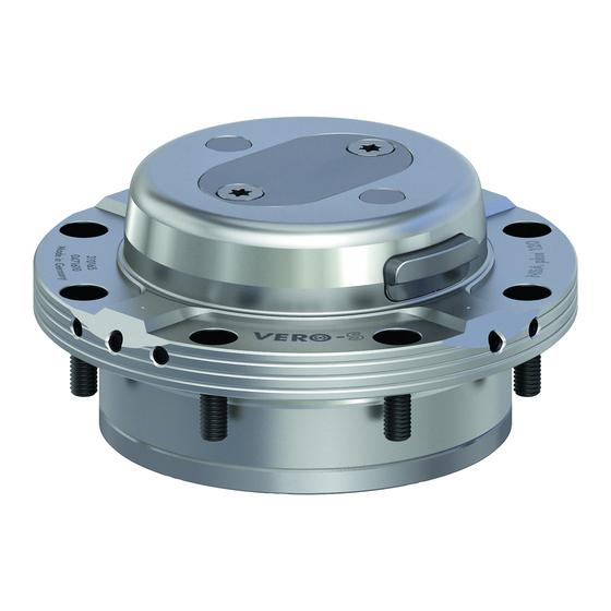
SCHUNK VERO-S NSA plus 120 Assembly And Operating Manual
Quick-change pallet system
Hide thumbs
Also See for VERO-S NSA plus 120:
- Assembly and operating manual (37 pages) ,
- Assembly and operating manual (36 pages)

Related Manuals for SCHUNK VERO-S NSA plus 120


Summary of Contents for SCHUNK VERO-S NSA plus 120
- Page 1 Translation of Original Operating Manual VERO-S quick-change pallet system NSA plus 120; NSA plus 160 Assembly and Operating Manual...
- Page 2 Imprint Imprint Copyright: This manual is protected by copyright. The author is SCHUNK GmbH & Co. KG. All rights reserved. Technical changes: We reserve the right to make alterations for the purpose of technical improvement. Document number: 0489070 Version: 06.00 | 27/06/2022 | en...
-
Page 3: Table Of Contents
Table of Contents Table of Contents About this manual .................... 5 Presentation of Warning Labels ................ 5 Applicable documents .................. 5 Basic safety notes .................... 6 Intended use...................... 6 Not intended use .................... 6 Notes on particular risks.................. 7 Product safety ...................... 9 2.4.1 Holding force and screw strength............ 10 2.4.2 Constructional changes, attachments, or modifications ...... 10 Personnel qualification.................. - Page 4 Table of Contents 14 Annex to Declaration of Incorporation .............. 37 06.00 | NSA plus 120; NSA plus 160 | VERO-S quick-change pallet system | en | 0489070...
-
Page 5: About This Manual
• Catalog data sheet of the purchased product * The documents marked with an asterisk (*) can be downloaded on our homepage www.schunk.com. 06.00 | NSA plus 120; NSA plus 160 | VERO-S quick-change pallet system | en | 0489070... -
Page 6: Basic Safety Notes
• It is used as a pressing tool, a chuck, a load-handling device or as lifting equipment. • It is used for turning applications without consulting SCHUNK. • It is used in working environments that are not permissible. • People work on machines or technical equipment that do not comply with the EC Machinery Directive 2006/42/EC, disregarding the applicable safety regulations. -
Page 7: Notes On Particular Risks
Basic safety notes 2.3 Notes on particular risks This product may pose a danger to persons and property if, for example: • It is not used as intended; • It is not installed or maintained properly; • The safety and installation instructions, local applicable safety and accident prevention regulations or the EC Machinery Directive are not observed. - Page 8 Basic safety notes WARNING Risk of injury to persons due to falling down of the fixture, pallet or workpiece by erroneous or negligent loosening of the clamping rings. During operation, incorrect or incautious loosening of the • clamping ring must be prevented by suitable measures (disconnection of power supply after locking, use of safety valves or safety switches).
-
Page 9: Product Safety
Operating the gripper in an environment in which it is subjected to abrasive dusts or corrosive and/or aggressive vapours and/or liquids requires the prior consent of SCHUNK. 06.00 | NSA plus 120; NSA plus 160 | VERO-S quick-change pallet system | en |... -
Page 10: Holding Force And Screw Strength
2.4.2 Constructional changes, attachments, or modifications Additional threads, bore holes or attachments which are not supplied as accessories by SCHUNK may affect safety. They may only be applied after obtaining the prior consent of SCHUNK. 2.5 Personnel qualification... -
Page 11: Organizational Measures
Only allow specialists to remedy malfunctions. Spare parts Only use original SCHUNK spare parts. Environmental regulations The applicable environmental regulations must be observed for all maintenance and repair work. -
Page 12: Warranty
Warranty 3 Warranty If the product is used as intended, the warranty is valid for 24 months from the ex-works delivery date under the following conditions: } 1.2 [/ 5] • Observe the applicable documents, • Observe the ambient conditions and operating conditions •... -
Page 13: Scope Of Delivery
Scope of delivery 4 Scope of delivery • Quick Change Pallet System • Assembly and Operating Manual • Enclosed pack NSA plus 1205 O-rings Ø 6 x 1.5, 8 Covering caps, 8 Fastening screws M6 NSAplus 1605 O-rings Ø 7 x 1.5, 8 Covering caps, 8 Fastening screws M8 4.1 Accessories •... -
Page 14: Technical Data
Technical data 5 Technical data NSA plus 0471610 0471710 Holding force 50 kN 75 kN Pull down force without turbo 3 kN 5 kN Pull down force with turbo 9 kN 15 kN Lifting force 100 kg 200 kg Lifting height 0.5 mm 0.5 mm Actuating pressure... -
Page 15: Assembly
Assembly 6 Assembly Actions before starting assembly Lift the quick-change pallet system carefully (e.g. using suitable lifting equipment) out of the packaging. CAUTION Risk of injury due to sharp edges and rough or slippery surfaces Wear personal protective equipment, particularly protective •... -
Page 16: General Assembly Notes
Assembly 6.1 General assembly notes If you wish to install the unit yourself, please request our drawing. If several clamping units are to be mounted in serial connection, please make sure that the evenness and deviation in height of the supporting surfaces from module to module keeps within 0.01 mm (relating to a depth gauge of 200 mm). -
Page 17: Fastening And Connection
Assembly 6.2 Fastening and connection If you wish to install the unit yourself, please request our drawing. 6.2.1 NSA plus 120 M5 (Torx) set-screw (remove before assembly) Unlocking connection Turbo connection Hose-free direct Hose-free direct connection connection (seal Ø 6 x 1.5) (seal Ø... - Page 18 Assembly The assembly module is positioned using the centering diameter of the installation space: Ø 90H6. All base-side air connections for the module ("Open module") and the turbo functions are closed with M5 x 4 set-screws. The air connection is made the standard way via the coupling bore on the lower face side of the quick-change pallet module.
-
Page 19: Nsa Plus 160
Assembly 6.2.2 NSA plus 160 M6 (Torx) set-screw (remove before assembly during use of the respective connection) Turbo connection Unlocking connection Hose-free direct Hose-free direct connection (seal Ø 7 x 1.5) connection (seal Ø 7 x 1.5) Clamping slide monitoring for module clamped Clamping slide Hose-free direct connection... - Page 20 Assembly The air connection is made the standard way via the coupling bore on the lower face side of the quick-change pallet module. For axial sealing, the O-rings must be inserted in the base-side O-ring seats of the clamping module. The accessory kit of the NSA plus 160 contains the Ø...
-
Page 21: Clamping Rings Sra, Srb, Src
To mount the clamping rings, screws of strength class 12.9 must } 6.4 [/ 23] be used. Only original SCHUNK clamping rings may be used. If the clamping rings are to be used in customer-owned devices, the customer must provide sufficiently dimensioned threaded holes or a sufficiently thick mounting material. - Page 22 Assembly Screw Customer-specific pallet or device Step Mounting Ø Installation Ø Fitting length = installation depth –1 Screw all clamping rings of equal height within 0.01 mm Tolerances and installation conditions Type SRA 120 RF 0471650 > 8 > 13 M8 > 9 > 12 M6 12 Ø 118 H6 Ø Ø...
-
Page 23: Screw Tightening Torques
Assembly ±0.015 for clamping ring type B Clamping ring type A, ±0.015 for clamping ring type C with positioning accuracy Clamping ring type B, for positioning in one direction Clamping ring type C, with centering clearance Clamping ring orientated towards air outlet openings on the clamping module 6.4 Screw tightening torques Tightening torques for mounting clamping rings... -
Page 24: Operation
Operation 7 Operation WARNING Risk of injury due to losing pallets or workpieces in the case of incorrect actuation caused by incorrect operation.Risk of injury due to compressed air hoses coming loose when connected improperly. Disconnect the energy supply after locking. •... -
Page 25: Function
Function 8 Function NOTICE In order to achieve the maximum lifting force, the clamping system should be actuated with an operating pressure of 6 bar. A lower operating pressure avoids proper decoupling of the clamping system 8.1 Clamping function Unlocking 1. -
Page 26: Lifting Function
Function 7. The clamping slides move outside and lock the clamping ring at the pallet self-locking as well as form-fit. Therefore pressure actuation of the clamping module during machining is not necessary. Centering of the clamping rings is done at the conical surface of the clamping module. -
Page 27: Dynamic Pressure Monitoring At The Clamping Slides
Function When using this control and cleaning function, it must be ensured that the clamping ring is in the right position orientation. The cylinder head countersinks of the clamping ring must not be positioned on the air outlet holes of the clamping module, since otherwise the blast air will escape and it will not be possible to build up a measurable dynamic pressure. -
Page 28: Pneumatic Circuit Diagram
Function 8.5 Pneumatic circuit diagram Actuation with Unlocking connection 6 bar Turbo connection Air control Slide monitoring for "module opened" Slide monitoring for "module clamped" Pneumatic circuit symbols 5/3 directional control valve, center position ventilated 3/2 directional control valve Pressure switch Pressure gauge Flow control valve For 2 bar... - Page 29 Function When controlling the NSA plus quick-change pallet system, the following must be observed: Turbo function: • The actuating pressure for the turbo function must not exceed 6 bar. Slide monitoring: • The max. pressure of the slide monitoring is 2 bar. •...
-
Page 30: Maintenance And Care
Risk of injury and risk of damage to the clamping module when opening the housing cover. If the clamping module has to be disassembled, ship the module to SCHUNK for repair. The covers of the clamping modules are spring-packaged may be removed only by trained personnel. -
Page 31: Trouble Shooting
Faulty air connections Check air supply Pressure drops below minimum Check operating pressure (min. 5 bar) Component is broken, e.g. through Replace module or send it to SCHUNK for overloading repair Tensile load to the clamping pin is too Reduce load... -
Page 32: Seal Kit And Part Lists
Seal kit and part lists 11 Seal kit and part lists 11.1 Seal kit lists NSA plus 120 (ID no. 0471612) Item Designation Quantity Bearing shell Quad ring Quad ring O-ring O-ring O-ring O-ring O-ring O-ring O-ring NSA plus 160 (ID no. 0471712) Item Designation Quantity... -
Page 33: Part Lists
Seal kit and part lists 11.2 Part Lists NSA plus 120 Item Designation Quantity Body Clamping slide Piston Cover Bearing shell Lifting pin Cover plate Countersunk screw Steel ball Countersunk screw Compression spring Quad ring Quad ring O-ring O-ring O-ring O-ring O-ring O-ring... - Page 34 Seal kit and part lists NSA plus 160 Item Designation Quantity Body Clamping slide Piston Cover Bearing shell Lifting pin Cover plate Countersunk screw Steel ball Countersunk screw Compression spring Quad ring Quad ring O-ring O-ring O-ring O-ring O-ring O-ring Set-screw O-ring Screw...
-
Page 35: Assembly Drawing
Assembly drawing 12 Assembly drawing 06.00 | NSA plus 120; NSA plus 160 | VERO-S quick-change pallet system | en | 0489070... -
Page 36: Translation Of The Original Declaration Of Incorporation
Directive 2006/42/EG, Annex II, Part 1.B of the European Parliament and of the Council on machinery. Manufacturer/ H.-D. SCHUNK GmbH & Co. Spanntechnik KG Distributor Lothringer Str. 23 D-88512 Mengen We hereby declare that on the date of the declaration the following partly completed machine complied with all basic safety and health regulations found in the directive 2006/42/EC of the European Parliament and of the Council on machinery. - Page 37 Annex to Declaration of Incorporation 14 Annex to Declaration of Incorporation according 2006/42/EG, Annex II, No. 1 B 1.Description of the essential health and safety requirements pursuant to 2006/42/EC, Annex I that are applicable and that have been fulfilled with: Product designation VERO-S quick-change pallet system Type designation 120 - 160...
- Page 38 Annex to Declaration of Incorporation Protection against mechanical hazards 1.3.7 Risks related to moving parts 1.3.8 Choice of protection against risks arising from moving parts 1.3.8.1 Moving transmission parts 1.3.8.2 Moving parts involved in the process 1.3.9 Risks of uncontrolled movements Required characteristics of guards and protective devices 1.4.1 General requirements...
- Page 39 Annex to Declaration of Incorporation Information 1.7.1 Information and warnings on the machinery 1.7.1.1 Information and information devices 1.7.1.2 Warning devices 1.7.2 Warning of residual risks 1.7.3 Marking of machinery 1.7.4 Instructions 1.7.4.1 General principles for the drafting of instructions 1.7.4.2 Contents of the instructions 1.7.4.3 Sales literature The classification from Annex 1 is to be supplemented from here...
- Page 40 Translation of Original Operating Manual H.-D. SCHUNK GmbH & Co. Spanntechnik KG Lothringer Str. 23 D-88512 Mengen Tel. +49–7572-7614-0 Fax +49-7572-7614-1099 info@de.schunk.com schunk.com Folgen Sie uns I Follow us...
Need help?
Do you have a question about the VERO-S NSA plus 120 and is the answer not in the manual?
Questions and answers