Table of Contents
Advertisement
Quick Links
FAU
AR
RES
CLE
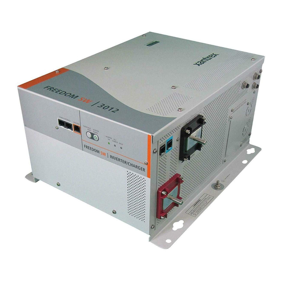
Freedom SW-RVC Inverter/Charger
FAU
LT
R
AC
IN
G
INVE
BLED
RTE
WA
RNIN
ER
ENA
RGIN
G
INV
LE
ERT
CHA
LT
EN
AB
GEN
T
ET
SUP
POR
CL
EA
R FAU
RES
LT
ET
INV
AB
EN
ERT
ER
LE
INV
ENA
ER
BLE
ERT
D
AC
IN
GEN
SUP
POR
T CHA
FAU
LT
RGI
NG
WA
RNIN
G
Installation Guide
Product Model Number
815-3012-02
Advertisement
Table of Contents

Subscribe to Our Youtube Channel
Related Manuals for Xantrex 815-3012-02


Summary of Contents for Xantrex 815-3012-02
- Page 1 INVE BLED RNIN RGIN R FAU T CHA RNIN Installation Guide Product Model Number Freedom SW-RVC Inverter/Charger 815-3012-02...
- Page 2 CANNOT BE GUARANTEED. APPROVED CONTENT IS CONTAINED WITH THE ENGLISH LANGUAGE VERSION WHICH IS POSTED AT http://www.xantrex.com/. NOTE: Visit http://www.xantrex.com/ , click Products, select a Product category, select a Product, and search the Product Documents panel for a translation of the English guide, if available.
- Page 3 Selecting and using Personal Protective Equipment (PPE) consult individual battery manufacturers for this information. and following safety work code practices. See NFPA 70E or CSA Z462. Related Information You can find more information about Xantrex products and services at http://www.xantrex.com/. 975-1057-01-01...
-
Page 4: Important Safety Instructions
Obey all safety Please Note: No responsibility is assumed by Xantrex for any consequences messages that follow this symbol to avoid possible arising out of the use of this material. -
Page 5: Safety Information
Safety Information Safety Information load. Turning the inverter/charger to Standby using the Power button on the panel will not reduce an electrical shock hazard. 8. The inverter/charger must be provided with an equipment- 1. Before using the inverter/charger, read all instructions and ground. -
Page 6: Precautions When Working With Batteries
Safety Information DANGER DANGER FIRE AND BURN HAZARD ELECTRIC SHOCK HAZARD • Do not expose the Freedom SW-RVC to rain, snow, or spray water. • Do not cover or obstruct the air intake vent openings and/or install in a zero- clearance compartment. •... -
Page 7: Precautions When Preparing To Charge
Precautions When Working With Batteries Precautions When Working With DANGER Batteries EXPLOSION HAZARD IMPORTANT: Battery work and maintenance must be done by • Charge only properly rated (such as 12 V) lead-acid (GEL, AGM, Flooded, or qualified personnel knowledgeable about batteries to ensure lead-calcium) rechargeable batteries because other battery types may compliance with battery handling and maintenance safety explode. -
Page 8: Precautions When Placing The Unit
Precautions When Preparing to Charge NOTES: Precautions When Preparing to 1. Mount and place the Freedom SW-RVC Inverter/Charger unit Charge away from batteries in a well ventilated compartment. 2. Always have someone within range of your voice or close enough to come to your aid when you work near a lead-acid WARNING battery. -
Page 9: Regulatory
Precautions When Placing the Unit Precautions When Placing the Regulatory Unit The Freedom SW-RVC is certified to appropriate US and Canadian standards. For more information see Specifications on page 72. The Freedom SW-RVC is intended to be used for recreational NOTICE vehicle and commercial applications. -
Page 10: Emi Information To The User
Reorient or relocate the receiving antenna. in the landfill. Increase the separation between the equipment and receiver. For more information on disposal, contact Xantrex. Connect the equipment into an outlet on a circuit different from that to which the receiver is connected. -
Page 11: Table Of Contents
CONTENTS Important Safety Instructions Step 4: Connecting the DC Cables Safety Information Step 5: Connecting the Battery Temperature Sensor (BTS) Precautions When Working With Batteries Precautions When Preparing to Charge Step 6: Connecting to the Network Precautions When Placing the Unit Step 7: Performing Checks Prior to Initial Start-Up Regulatory Step 8: Testing Your Installation... - Page 12 Setting Load Sense on the Secondary Unit Wiring Schematic Charger Settings in Stacked Configuration Calculations Examples Battery Information Battery Capacity About Amp-hours Estimating Battery Requirements Calculating Battery Size Battery Banks Battery Bank Sizing Worksheet Restrictions on Motor Size Battery Cabling and Connections Battery Parallel Connection Battery Series Connection Battery Series-Parallel Connections...
-
Page 13: Introduction
Figure 1 What’s In The Box NOTE: If any of the items are missing, contact customer service or any authorized Xantrex dealer for replacement. See ABOUT THIS GUIDE on page 3. IMPORTANT: Keep the carton and packing material in case you need to return the Freedom SW-RVC for servicing. - Page 14 This page is intentionally left blank. [2]...
-
Page 15: Installation
INSTALLATION This section provides sample installation information as a guide for your installation. For your convenience, the overall procedure is divided into these main steps: Before You Begin the Installation Installation Codes Basic Installation Procedures 975-1057-01-01... -
Page 16: Before You Begin The Installation
Before You Begin the Installation Before You Begin the Installation Codes Governing installation codes vary depending on the specific Installation location and application of the installation. Some examples Before beginning your installation: include the following: Read this entire Installation guide so you can plan the The U.S. -
Page 17: Basic Installation Procedures
Basic Installation Procedures Basic Installation Procedures This section provides sample installation information as a guide for your installation. For your convenience, the overall procedure is divided into these main steps: Planning the Installation Step 1: Choosing a Location for the Unit Step 2: Mounting the Unit Step 3: Connecting the AC Input and AC Output Wires Step 4: Connecting the DC Cables... -
Page 18: Planning The Installation
Refer to the guide to determine page 30. the type of network layout to install, as well as guidelines for installing the network. This guide is available for download at www.xantrex.com. Freedom SW-RVC Installation Guide... - Page 19 Basic Installation Procedures Figure 2 Typical Network AC Input AC inputs to a dual AC lines can be supplied from a for Dual AC split-phase or dual-input AC source such as the Lines utility grid (power company), a generator, or the AC Panel Inverter Load Panel...
- Page 20 Basic Installation Procedures Dual This source type has two line inputs, one neutral, AC Loads The Freedom SW-RVC is intended to power loads input: and one ground. Unlike the split-phase type, the consisting of 120 volts AC appliances. two lines are in phase (not out of phase), and must In Invert mode, the Freedom SW-RVC connects come from the same source.
- Page 21 Basic Installation Procedures Split No more than 30 amps max in each line. GFCI A GFCI (ground fault circuit interrupter) is a device phase Requirement that de energizes a circuit when a current to ground Because the two lines are out of phase, the input: exceeds a specified value that is less than that currents from each line subtract in the neutral, and...
- Page 22 Basic Installation Procedures Disconnect Each system requires a method of disconnecting Type Devices the AC circuits. If the overcurrent protection device The type of wiring required varies according to the is a circuit breaker, it will also serve as the electrical codes or regulations applicable to your disconnect.
- Page 23 Basic Installation Procedures Size of AC Input Wiring Size of AC Output Wiring Wire size must be coordinated with the overcurrent Wire size must be coordinated with the current the protection provided ahead of the wire involved, in wiring will carry. This current may be determined accordance with the electrical codes or regulations by the 25-amp maximum inverter current, or by the applicable to your installation.
- Page 24 Basic Installation Procedures Some conditions for Freedom SW-RVC: Size of Wiring Downstream of the AC Output Breaker If the input wiring is split-phase, the output wiring must be sized to coordinate with the The wiring used between the AC output breaker breakers used on the input.
- Page 25 Basic Installation Procedures Suitability See Battery Sizing Example on page 68 for This automatic neutral-to-ground bonding system information on: requires AC input sources with bonded neutral. Estimating the battery size that will meet your requirements. This will be the case in most situations: in a utility feed, at an external AC hook-up, or a generator Designing battery banks.
- Page 26 Basic Installation Procedures Size and Length The DC circuit from the battery to the See Table 3 for required DC cable length, cable Disconnects inverter/charger must be equipped with a size and required fuse size for the Freedom and Over- disconnect and overcurrent protection device.
- Page 27 Basic Installation Procedures UnpackingandInspectingtheFreedom SW- DC Grounding The inverter/charger DC (chassis) ground terminal needs to be connected to the vehicle chassis by a minimum No. 8 AWG copper conductor that is either insulated (green) wire CAUTION rated 75 °C or bare copper. PHYSICAL INJURY HAZARD NOTICE The Freedom SW-RVC Inverter/Charger is heavy.
- Page 28 Basic Installation Procedures Save the original shipping carton and packing materials. If Materials the inverter/charger needs to be returned for service, it You will need the following materials to complete your should be shipped in the original carton. Packing the installation: Freedom SW-RVC in the original shipping carton is also a Strain-relief clamp(s) for AC cables (not provided): 3/4"...
-
Page 29: Step 1: Choosing A Location For The Unit
Basic Installation Procedures Step 1: Choosing a Location for the Close to The length and size of your DC cables will affect performance. Use the DC cables recommended battery Unit in Table 3 on page 11. The unit should not be compartment installed in the battery compartment due to the possible presence of explosive hydrogen gas... - Page 30 Basic Installation Procedures Protected Never place the inverter/charger directly above the batteries—gases from battery will corrode and from battery damage the inverter/charger. If the acid and inverter/charger is installed in a compartment gases above the batteries, make sure there is a solid, gas-impermeable wall dividing the two compartments.
-
Page 31: Step 2: Mounting The Unit
Basic Installation Procedures The Freedom SW-RVC mounting orientations are shown in Step 2: Mounting the Unit Approved Mounting Orientations on page 33. Considerations Mount your inverter/charger before you connect any wires or Before mounting the Freedom SW-RVC, take the following two cables. - Page 32 Basic Installation Procedures Figure 3 Approved Mounting Orientations Approved Orientation Mounting Comment Orientation? A - Suitable only for non-marine applications with no risk of Desktop A - Yes Inverter Reset Enable Inverter Charge Fault Xanbus Interface condensation or dripping water. Mount B - Yes when used with inverter drip...
- Page 33 Basic Installation Procedures Approved Orientation Mounting Comment Orientation? A - Yes A - On a vertical surface with DC terminals facing right. Wall Mount DC on B - Yes when used B - On a vertical surface with DC terminals facing right with the Right with an inverter front panel facing down.
- Page 34 Basic Installation Procedures Approved Orientation Mounting Comment Orientation? Not allowed Not acceptable. Wall Mount DC Down This orientation does not meet regulatory requirements. Freedom SW-RVC Installation Guide...
-
Page 35: Step 3: Connecting The Ac Input And Ac Output Wires
Basic Installation Procedures General AC Wiring Considerations Step 3: Connecting the AC Input and AC and DC Do not mix AC and DC wiring in the same AC Output Wires Wiring conduit or panel. Consult the applicable Separation installation code for details about DC wiring and DANGER AC wiring in vicinity to each other. - Page 36 Basic Installation Procedures Connecting AC Input Wires AC Wiring For your reference, the AC wiring compartment Compartment is shown in Figure 4 on page 37. Figure 4 shows the wiring compartment, which contains a grounding bus (used to wire the AC input and output ground wires) AC Knockouts There are two dual 1.0"/ 3/4"...
- Page 37 Basic Installation Procedures 7. Using a 1/4" blade slot screwdriver, loosen the terminal NOTICE screws on the terminals. Do not remove the screws. 8. Connect the line and neutral wires to the input terminals EQUIPMENT DAMAGE (labeled AC Input on the terminal block, General AC Wiring Considerations on page 36): Connect Line 1 to L1, Neutral Connect wires to the correct terminals in the terminal block to N, Line 2 to L2.
- Page 38 Basic Installation Procedures Connecting the AC Output Wires Terminals Line for Dual Output Lines for Single Output Neutral 2 Unused NOTICE Line 2 Unused EQUIPMENT DAMAGE Neutral 1 Neutral Do not connect the output of the inverter to any AC source. Line 1 Line Failure to follow these instructions can result in equipment...
-
Page 39: Step 4: Connecting The Dc Cables
Basic Installation Procedures 2. Cut the DC ground cable to the required length. Strip off Step 4: Connecting the DC Cables enough insulation so you can install the terminals you will DC Connection Precautions be using. It is recommended to use crimp connectors. The connector should be designed for a 1/4"... - Page 40 Basic Installation Procedures Guidelines for Routing the DC Cables Connecting the DC Cables to the Follow these guidelines to ensure maximum performance. Inverter/Charger DANGER WARNING ELECTRICAL SHOCK AND FIRE DAMAGE FIRE HAZARD Use only appropriately sized copper cable. Loose connections, Route the cables away from sharp edges that might damage improper connections, and under-rated cables will overheat.
- Page 41 Basic Installation Procedures shorting. See Recommended Fuse Size on page 27 for Figure 5 DC Cable Connections required fuse or breaker size. 3. Open the DC disconnect switch or turn off the DC circuit breaker. 4. Connect one connector on the POSITIVE (+) cable to the POSITIVE DC terminal on the inverter/charger, as shown in Figure 4.
- Page 42 Basic Installation Procedures 10. To protect the DC terminals, attach the DC terminal covers DC Grounding (Figure 6 ) to the inverter/charger, using the screws The Chassis Ground point on the inverter/charger is used to provided. connect the chassis of the inverter/charger to your system’s DC Figure 6 DC Terminal Covers grounding point, as required by regulations for some installations.
- Page 43 Basic Installation Procedures Figure 7 Chassis ground point e rt a rg u lt 975-1057-01-01...
-
Page 44: Step 5: Connecting The Battery Temperature Sensor (Bts)
Basic Installation Procedures Mounting Options Step 5: Connecting the Battery You can mount the BTS in one of two ways: Temperature Sensor (BTS) Mounting the sensor to the negative battery post allows the Installing a battery temperature sensor (BTS) extends the life of a internal battery temperature to be sensed and provides the battery by preventing overcharging in warm temperatures and most accurate results. - Page 45 Basic Installation Procedures 6. You may need to bend the ring terminal crimp and/or wires Mounting to the Negative Battery Terminal slightly downward to allow the sensor to seat flush to the To mount the sensor on the negative battery terminal: top surface of the upper ring terminal.
- Page 46 Basic Installation Procedures Figure 10 Connecting the BTS Cable to BTS Port Mounting to the Side of the Battery Case To mount the sensor on the battery case: Figure 11 BTS Mounted on the Battery Case In ve In ve le d ar ge ul t...
- Page 47 Basic Installation Procedures 6. Peel the protective backing from the self-adhesive strip on the rear of the sensor. 7. Press the sensor firmly against the clean side of the battery to fix it in place (as shown in Figure 11 ). 8.
-
Page 48: Step 6: Connecting To The Network
Basic Installation Procedures Figure 12 Connecting to a RV-C Network Port Step 6: Connecting to the Network For your reference, Figure 12 shows where the network connections are made on the Freedom SW-RVC. To connect the Freedom SW-RVC to the RV-C network: Plug a network cable connected to the RV-C network into either one of the two RV-C Interface network ports on the Freedom SW-RVC. -
Page 49: Step 7: Performing Checks Prior To Initial Start-Up
Basic Installation Procedures Step 7: Performing Checks Prior to Initial Start-Up Before testing your installation, ensure these conditions are met: Chassis and AC grounds are properly installed. AC input connections and AC output connections are wired correctly on the terminal block and not reversed. Positive (+) battery cable is connected to the positive (+) battery terminal through the DC fuse and disconnect switch or DC circuit breaker. -
Page 50: Step 8: Testing Your Installation
Basic Installation Procedures There are several tests to be performed for testing your Step 8: Testing Your Installation installation. These tests will verify that: the Freedom SW-RVC works in invert mode WARNING the Freedom SW-RVC works in charge mode the Freedom SW-RVC works in AC bypass mode ELECTRICAL SHOCK HAZARD If the test fails at any point, go to Step 7: Performing Checks Prior Do not use the INVERTER ENABLE button on the Freedom... - Page 51 Basic Installation Procedures Testing in Invert Mode TestinginChargeModeandACBypassMode To test the Freedom SW-RVC in invert mode, using a 100 1. Close the AC supply breaker to supply AC power to the unit. watt light bulb as the test load: 2. To verify that the Freedom SW-RVC starts charging: 1.
-
Page 52: Stacking Features
STACKING FEATURES The Freedom SW-RVCs can support two stacking Parallel Stacking configurations. This gives the system engineer and/or installer A parallel stacking configuration allows the inverter and charger more options to work with when tailoring a system to meet load capacity of a system to be doubled. - Page 53 Figure 14 Parallel Stacking Using Two Freedom SW-RVC units NOTICE Main Distribution Panel EQUIPMENT DAMAGE NEUTRAL WARNING: INCORRECT BATTERY Do NOT connect a stacking cable to the STACKING port on the Wiring box cover must be in place during front panel of a Freedom SW-RVC to configure two units for use to reduce risk of injury to persons BATTERY NEGATIVE...
-
Page 54: Series Stacking
Series Stacking Series Stacking NOTICE A series stacking configuration allows two inverters to be GENERAL PRECAUTIONS configured to produce 120 and 240 volts AC, also known as, a single-phase three-wire configuration. For example, a Freedom Install stacked inverter/chargers in close proximity to each other. -
Page 55: Stacking Cable
Figure 15 Series Stacking Using Two Freedom SW-RVCs Stacking Cable Main Distribution Panel For series stacking (120 and 240 volts), connect the Xantrex WARNING: INCORRECT BATTERY NEUTRAL stacking cable between the two STACKING ports. Figure 16 Stacking Cable for Series Stacking... -
Page 56: Series Stacking Operation
DC Connections for Stacked Inverters DC Connections for Stacked Series Stacking Operation The inverter is designed to accept power input from a single- Inverters phase, three-wire 120/240-volt AC system with 120 volts to each Use individual overcurrent devices between the battery positive inverter. -
Page 57: Neutral Wiring For Stacked Inverters
Wiring box cover must be in place during use to reduce risk of injury to persons BATTERY NEGATIVE AC GROUNDS (BEHIND COVER) DC Ground or Grounding Electrode Terminal. See manual for more information. xantrex Vehicle Chassis 12Vdc Vented Battery Ground Enclosure xantrex 975-1057-01-01... -
Page 58: Configuring System For Stacked Operation
Configuring System for Stacked Operation Figure 18 Neutral Wiring for Stacking Configuring System for Stacked Main NEUTRAL Distribution Panel Operation WARNING: INCORRECT BATTERY Verify all DC and AC connections. Check RV-C network Wiring box cover must be in place during use to reduce risk of injury to persons BATTERY connections and ensure that terminators are installed at devices... -
Page 59: Load Sense In Series Stacking
Load Sense in Series Stacking 3. From the RV-C system device controller, if available, Load Sense Operation in navigate to the device screen for the inverter you want to configure as a secondary device. Parallel Stacking 4. Navigate to the Advanced Settings screen and select When two inverter/chargers are stacked for parallel operation, Stacking. -
Page 60: Disabling Load Sense On The Primary Unit
Load Sense in Series Stacking Disabling Load Sense on the Setting Load Sense on the Primary Unit Secondary Unit In parallel stacking, load sense on the primary unit will not function The secondary unit will behave in one of two ways depending on properly. -
Page 61: Wiring Schematic
Wiring Schematic Wiring Schematic Charger Settings in Stacked NOTE: Please refer to the Stacking Configuration sheet that Configuration shows the wiring schematic employed between two Freedom The Freedom SW-RVC includes a maximum 150A charger. When SW-RVC inverter/chargers that are stacked in parallel and in using two stacked inverter/chargers connected to the same series. -
Page 62: Calculations
Wiring Schematic For a Flooded type battery bank, the preferred charge rate (in Calculations Amps) is usually 10-15% of C where C = battery bank’s total Once installed and configured, each Freedom SW-RVC charger in Amp-hour capacity. However, the industry-accepted maximum the dual configuration should be set to its own bulk charge current charge rate is 25% of C. -
Page 63: Examples
Wiring Schematic maximum possible 150A charger capacity is set to a Max Chg Examples Rate of 100 (%) then its full 150A of current can be delivered into Example 1: the battery bank. However, if this is too high, the installer/operator System composed of two stacked Freedom SW-RVCs. - Page 64 Wiring Schematic Example 2: System composed of two stacked Freedom SW-RVCs. Each Freedom SW-RVC has a maximum charge capacity of 150A. The two stacked inverter/chargers connected to the same battery bank can possibly produce a total of 300A. The industry’s commonly accepted practice suggests a typical Flooded battery bank capacity (C) of 600Ah should not be charged beyond 25% of its capacity (150A).
-
Page 65: Battery Information
BATTERY INFORMATION Battery Capacity About Amp-hours A number of different standards are used to rate battery energy Battery size or capacity is just as important as the battery type storage capacity. Automotive and marine starting batteries are selected for use with the Freedom SW-RVC. The batteries are normally rated in cranking amps. -
Page 66: Estimating Battery Requirements
Estimating Battery Requirements Estimating Battery Size the batteries at approximately twice the estimated total amp- hour usage. Doubling the expected amp-hour usage ensures that Requirements the batteries will not be overly discharged and extends battery life. Calculating Battery Size Do not skip this doubling step. More capacity is better since you will have more reserve capacity, be better able to handle large Step 1: Compute Amp-hours loads and surge loads, and your battery won’t be discharged as... -
Page 67: Battery Banks
Estimating Battery Requirements Figure 19 Battery Sizing Example Battery Banks As your power requirements increase, you may need to use more Daily watt-hours (A) Power (B) Operating needed for this Appliance than one battery to obtain sufficient capacity. Batteries can be Consumption Time per Day appliance... -
Page 68: Battery Bank Sizing Worksheet
Restrictions on Motor Size Restrictions on Motor Size Battery Bank Sizing Worksheet The following worksheet is a guide to help you determine your An appliance may require three to six times its normal running battery needs. Be generous in estimating the time for which you current in order to start. -
Page 69: Battery Cabling And Connections
5 BATTERY CABLING AND CONNECTIONS Several smaller batteries can be connected to create a battery Battery Parallel Connection bank of substantial size. You can connect batteries in three Batteries are connected in parallel when all the positive terminals ways: in parallel, series, or series-parallel. of a group of batteries are connected and then, separately, all the To make a larger battery bank, connect individual batteries with negative terminals are connected. -
Page 70: Battery Series Connection
Battery Series Connection Battery Series Connection Battery Series-Parallel When batteries are connected with the positive terminal of one Connections battery to the negative terminal of the next battery, they are As the name series-parallel implies, both the series and parallel connected in series. -
Page 71: Specifications
SPECIFICATIONS NOTE: Specifications are subject to change without prior notice. Environmental Specifications Physical Specifications Nominal Ambient temperature 40 °C (104 °F) Invert mode: L × W × H 387×343×197 mm Operating range (full power) –20 to 40 °C (–4 to 104 °F) (15.25×13.5×7.75 in.) Load @ maximum ambient 2600W @ 60 °C... - Page 72 NOTE: All inverter specifications are at nominal conditions: 12 NOTE: All charging specifications are at nominal conditions: volts DC inverting 120 volts AC, unless otherwise specified. ambient temperature of 77 °F (25 °C), 120 VAC, 60 Hz input, unless otherwise specified. Inverter Specifications Charger Specifications Output wave form pure sine wave (true sine wave)
- Page 73 NOTE: All transfer specifications are at nominal conditions: Charger Specifications ambient temperature of 77 °F (25 °C), 120 VAC, 60 Hz input, AC input power factor (at full unless otherwise specified. > 0.95 charge rate) AC input current 24A max. (including pass-thru) Transfer and General Specifications AC input voltage 120 VAC...
- Page 74 Accessories Cables Name Part number 3-ft network cable (0.9 m) 809-0935 25-ft network cable (7.6 m) 809-0940 75-ft network cable (22.9 m) 809-0942 Stacking cable for series stcking 808-9005 Hardware Name Part number Freedom SW-RVC On/Off Switch 808-9002 GFCI receptacle 808-9003 Inverter drip shield 808-9004...
- Page 75 This page is intentionally left blank. [2]...
- Page 76 (Toll Free USA/Canada) +1 800 670 0707 (Outside USA/Canada) +1 408 987 6030 Printed in: 975-1057-01-01 Rev A...
Need help?
Do you have a question about the 815-3012-02 and is the answer not in the manual?
Questions and answers