Table of Contents
Advertisement
TM
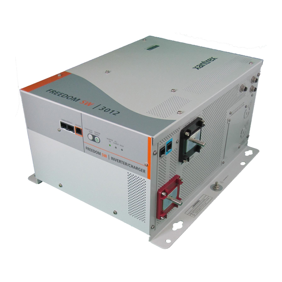
Freedom SW 3012 shown.
Freedom SW
Sine Wave Inverter/Chargers
LT
FAU
IN
ER
AC
ING
ERT
WA
RN
INV
AB
LED
G
RT
ER
EN
AR
GIN
VE
LE
CH
IN
AB
N
UL
T
EN
GE
PPO
RT
R FA
T
SU
EA
RE
SE
CL
CL
EA
R FA
UL
RE
T
SE
T
IN
VE
EN
RT
ER
AB
LE
INV
EN
ER
TER
AB
LED
AC
GE
IN
SU
PPO
N
RT CH
AR
GIN
G
WA
FA
ULT
RN
ING
TM
Installation Guide
Model Numbers
815-3012, 815-3024
815-2012, 815-2024
Advertisement
Table of Contents

Related Manuals for Xantrex Freedom SW 815-3012


Summary of Contents for Xantrex Freedom SW 815-3012
- Page 1 R FA R FA RT CH Installation Guide Freedom SW 3012 shown. Freedom SW Model Numbers 815-3012, 815-3024 815-2012, 815-2024 Sine Wave Inverter/Chargers...
-
Page 3: Contact Information
Web: www.xantrex.com Xantrex Technology USA Inc. All rights reserved. No part of this document may be reproduced in any form or disclosed to third parties without the express written consent of: Xantrex Technology USA Inc., 541 Roske Drive, Suite A, Elkhart, Indiana, USA 46516. -
Page 4: About This Guide
About This Guide Purpose Conventions Used The purpose of this Installation Guide is to provide explanations and The following conventions are used in this guide. procedures for installing the Freedom SW Inverter/Charger. Scope STATEMENT OF HAZARD The Guide provides safety and installation guidelines as well as information Contains statements of avoidance or strict compliance. - Page 5 IMPORTANT: These notes describe things which are important for you to know, however, they are not as serious as a caution or warning. Related Information You can find more information about Xantrex Technology USA Inc. as well as its products and services at www.xantrex.com. 97-0020-01-01...
-
Page 6: Important Safety Instructions
Important Safety Instructions IMPORTANT: R EAD AND SAVE THIS NSTALLATION UIDE FOR FUTURE REFERENCE ELECTRICAL SHOCK HAZARD • Do not expose the Freedom SW to rain, snow, spray, or bilge water. This chapter contains important safety and installation instructions for the This inverter/charger is designed for marine applications only when Freedom SW Inverter/Charger (Freedom SW). - Page 7 NOTES: Follow these instructions and those published by the battery FIRE AND BURN HAZARD manufacturer and the manufacturer of any equipment you intend to use • Do not cover or obstruct the air intake vent openings and/or install in in the vicinity of the battery. Review cautionary markings on these a zero-clearance compartment.
-
Page 8: Precautions When Working With Batteries
Precautions When Working With Batteries Use extra caution to reduce the risk or dropping a metal tool on the battery. It could spark or short circuit the battery or other electrical parts and could cause an explosion. BURN FROM HIGH SHORT-CIRCUIT CURRENT, FIRE AND EXPLO- Batteries can produce a short circuit current high enough to weld a ring SION FROM VENTED GASES HAZARDS or metal bracelet or the like to the battery terminal, causing a severe... - Page 9 Precautions When Preparing to Charge Precautions When Placing the Inverter/Charger RISK OF DAMAGE TO THE INVERTER/CHARGER EXPOSURE TO CHEMICALS AND GASES HAZARD • Never allow battery acid to drip on the inverter/charger when reading • Make sure the area around the battery is well ventilated. gravity, or filling battery.
- Page 10 Regulatory FCC Information to the User The Freedom SW Inverter/Charger is certified to appropriate US and This equipment has been tested and found to comply with the limits for a Canadian standards. For more information see “Regulatory Approvals” on Class B digital device, pursuant to part 15 of the FCC Rules. These limits the Specifications section in the Owner’s Guide.
-
Page 11: Table Of Contents
Contents Important Safety Instructions ..................iv Introduction . - Page 12 DC Components ..................16 Batteries .
- Page 13 Step 5: Connecting the Battery Temperature Sensor (BTS) ............35 Mounting Options .
- Page 14 Inverter/Charger Physical Specifications ................52 Battery Information .
-
Page 15: Introduction
Introduction The Installation Guide provides detailed information for installing the Freedom SW Inverter/Charger and the battery temperature sensor, wiring the inverter/charger to the AC and DC circuits, and connecting the inverter/ charger to the Xanbus system. The Freedom SW is a Xanbus-enabled device that typically powers the Xanbus system. -
Page 16: Materials List
• two sets of nuts and washers for the DC terminals. Owner’s Guides NOTE: If any of the items are missing, contact Xantrex or any authorized Freedom SW 3012 shown Xantrex dealer for replacement. See “Contact Information” on page i. -
Page 17: Installation Information
Installation Information Before You Begin the Installation Installation Codes Before beginning your installation: Applicable installation codes vary depending on the specific location and application of the installation. Some examples are: • Read the entire Installation Guide so you can plan the installation from beginning to end. -
Page 18: About The Xanbus System
About the Xanbus System Xanbus System The Xanbus system includes the Freedom SW and other Xanbus-enabled devices. The Freedom SW is the device in a Xanbus system that typically provides network power—500 mA at 12 volts DC. All of the Xanbus- enabled devices, such as the Freedom SW, the SCP, and the AGS are able to communicate their settings and activity to each other. -
Page 19: Xanbus-Enabled Products And Accessories
Low Battery Fault Enter Func Xanbus System Control Panel (SCP) FG A: 809-0921 For detailed instructions and a complete list of Xanbus-enabled devices, visit www.xantrex.com 3-ft cable 25-ft cable 75-ft cable Product/Accessory (Shown above) Product Number/s Product/Accessory (Not Shown) Product Number/s... -
Page 20: Planning The Installation
Planning the Installation Two Key Performance Factors This section provides information to help you plan for a basic installation of the Freedom SW. Two key factors in particular will have a major impact on system As your system configuration is determined, record the details in performance. -
Page 21: Planning Preparations
AC Input for Single AC Line Models guidelines for installing the network. This guide is available for • AC Loads download at www.xantrex.com • AC Disconnect and Over-Current Protection Device • Distribution Panels •... - Page 22 Planning Preparations IMPORTANT: Figure 3 does not show Sine Wave all required grounding or overcurrent Inverter/Charger protection. Always hire or you yourself must be a qualified installer to ensure that all electrical safety requirements are System Control Panel (SCP) Automatic Generator Start (AGS) met before, during, and after installation.
- Page 23 Planning Preparations IMPORTANT: Read Owner’s and In- stallation Guides prior to installation. 15 A TO AC APPLIANCE HOT BUS Always refer to local and national LOADS 20 A electrical codes for proper wire and breaker sizes prior to installation. Neutral OPTIONAL GFCI duplex receptacle special kit 15 A output limit...
- Page 24 Planning Preparations INVERTER AC SUB PANEL (TYPICAL) IMPORTANT: Read Owner’s and In- stallation Guides prior to installation. TO AC APPLIANCE 30 A Always refer to local and national HOT BUS LOADS electrical codes for proper wire and breaker sizes prior to installation. Neutral OPTIONAL GFCI duplex receptacle special kit...
-
Page 25: Ac Components
Planning Preparations AC Components NOTE: Unless otherwise referenced specifically by product name, the AC Input for Dual AC Line Models components refer to all models of Freedom SW inverter/chargers. AC inputs (to a dual AC line model such as Freedom SW 3012 inverter/ charger) can be supplied from a split-phase or dual-input AC source such as AC Input for Single AC Line Models the utility grid (power company), a generator, or the output of a transfer... -
Page 26: Ac Output
Planning Preparations AC Output AC Disconnect and Over-Current Protection Device The output voltage on Freedom SW inverter/chargers is 120Vac. The AC To meet CSA, UL, and electrical code requirements, and to protect system output line configuration depends on the model. wiring, the AC inputs and outputs of the inverter/charger must be provided •... -
Page 27: Distribution Panels
Consult all applicable codes. AC Wiring Tested GFCIs Compliance with UL standards requires that Xantrex test and recommend Definition AC wiring includes input wiring (all the wires and connectors specific GFCIs for use on the output of the inverter. Table 1 lists models... - Page 28 Planning Preparations Size of AC Input Wiring Wire size must be coordinated with the Some conditions for Freedom SW: overcurrent protection provided ahead of the wire involved, in accordance • If the input wiring is split-phase, the output wiring must be sized to with the electrical codes or regulations applicable to your installation.
-
Page 29: Ac Output Neutral Bonding
Planning Preparations AC Output Neutral Bonding The AC source must have its neutral conductor bonded to ground. Bonding system The Freedom SW provides a system that automatically connects the neutral conductor of the inverter’s AC output circuit to safety ground (“bonding” it) while the inverter/charger is inverting, and disconnects it (“unbonding”... -
Page 30: Dc Components
Planning Preparations DC Components Table 3 Recommended Battery Cable Sizes Conduit Free Air Batteries Model Typical Amps Cable Length Cable Length Cable Length Cable Length < 5 ft. 5 to 10 ft. < 5 ft. 5 to 10 ft. The Freedom SW system requires a 12- or 24-volt (depending on the Freedom SW 2012 250 kcmil 250 kcmil... -
Page 31: Dc Disconnects And Over-Current Devices
Planning Preparations DC Disconnects and Over-Current Devices DC Grounding The DC circuit from the battery to the inverter/charger must be equipped Recreational Vehicles The inverter/charger DC (chassis) ground terminal with a disconnect and overcurrent protection device. Refer to your needs to be connected to the vehicle chassis by a minimum No. 8 AWG applicable installation code. -
Page 32: Unpacking And Inspecting The Freedom Sw Inverter/Charger
Unpack the unit and check the materials list. If anything is missing from the shipping box, contact Xantrex Customer Service. See person to safely lift and mount. Xantrex recommends that two people lift “Contact Information” on page i. and mount the unit. Always use proper lifting techniques during installation to prevent personal injury. -
Page 33: Installation Tools And Materials
Six 1/4"–20 1.25" length steel screws or bolts to mount the unit NOTE: For a list of tools and materials required to install the network, refer to the Xanbus System Installation Guide, which is available for download at www.xantrex.com. 97-0020-01-01... -
Page 34: Installing The Inverter/Charger
Installing the Inverter/Charger Overview This section provides detailed information on installing the Freedom SW. The overall procedure is divided into eight steps: Step 1: Choosing a Location for the Inverter/Charger on page 21, Step 2: Mounting the Inverter/Charger on page 23, Step 3: Connecting the AC Input and AC Output Wires on page 26, Step 4: Connecting the DC Cables on page 30, Step 5: Connecting the Battery Temperature Sensor (BTS) on page 35,... -
Page 35: Step 1: Choosing A Location For The Inverter/Charger
Failure to follow these instructions will result in death or serious Clearance Allow as much space around the inverter/charger as injury. possible. Xantrex recommends that other objects and surfaces be at least 3 inches (76 mm) away from the ventilation openings for best performance. 97-0020-01-01... - Page 36 Installing the Inverter/Charger Safe Locate the inverter/charger away from battery in a separate well ventilated compartment. Do not install the inverter/charger in any compartment containing flammable gases or liquids like gasoline. Close to The length and size of your DC cables will affect battery performance.
-
Page 37: Step 2: Mounting The Inverter/Charger
The Freedom SW Inverter/Charger is heavy (see “Inverter/Charger Physical Specifications” on page 52) The unit is too heavy for one person to safely lift and mount. Xantrex recommends that two people lift and mount the unit. Always use proper lifting techniques during installation to prevent personal injury. - Page 38 Installing the Inverter/Charger Figure 6 Mounting Orientations Approved Mounting Orientation Orientation? Comment Desktop Mount Ideal. Inverter Reset Enable Inverter Charge Fault Xanbus Interface Upside-down Mount Yes (for non-marine Suitable only for non-marine applications applications only) with no risk of condensation or dripping water.
- Page 39 Installing the Inverter/Charger Approved Mounting Orientation Orientation? Comment Wall Mount DC on Right On a vertical surface with DC terminals facing right. IMPORTANT: This orientation is also suitable for marine applications only with the installation of additional drip protection. Wall Mount DC Up Not acceptable.
-
Page 40: Step 3: Connecting The Ac Input And Ac Output Wires
Installing the Inverter/Charger Step 3: Connecting the AC Input and AC Output Wires General AC Wiring Considerations AC and DC Wiring Separation Do not mix AC and DC wiring in the FIRE, ELECTRICAL SHOCK, AND ENERGY HAZARDS same conduit or panel. Consult the applicable installation code for details Make sure wiring being connected to the inverter/charger is disconnected about DC wiring and AC wiring in vicinity to each other. -
Page 41: Connecting Ac Input Wires
Installing the Inverter/Charger Connecting AC Input Wires Figure 7 shows the wiring compartment, which contains a grounding bus EQUIPMENT DAMAGE (used to wire the AC input and output ground wires) and a terminal block The terminal block is split into INPUT and OUTPUT sections. Damage (used to wire the AC input and AC output connections). - Page 42 Installing the Inverter/Charger Connect the line and neutral wires to the input terminals (labeled AC Input on the terminal block, Figure 7 on page 27). Freedom SW 3012/3024: Connect Line 1 to L1, Neutral to N, Line 2 to L2. Freedom SW 2012/2024: Connect Line to L, Neutral to N, Ground to G.
-
Page 43: Connecting The Ac Output Wires
Installing the Inverter/Charger Connecting the AC Output Wires Freedom SW 3012/3024 Line for Lines for Terminals Dual Output Single Output Neutral 2 Unused Line 2 Unused EQUIPMENT DAMAGE Neutral 1 Neutral Do not connect the output of the inverter to any incoming AC source. Line 1 Line Failure to follow these instructions can damage the unit and/or... -
Page 44: Step 4: Connecting The Dc Cables
Cut the DC ground cable to the required length. Strip off enough insulation so you can install the terminals you will be using. Xantrex recommends the use of crimp connectors. The connector ELECTRICAL SHOCK HAZARD should be designed for a 1/4" stud size to connect to the Freedom SW. -
Page 45: Guidelines For Routing The Dc Cables
Installing the Inverter/Charger Guidelines for Routing the DC Cables Follow these guidelines to ensure maximum performance. ELECTRICAL SHOCK AND FIRE HAZARD Route the cables away from sharp edges that might damage the insulation. Avoid sharp bends in the cable. Failure to follow these instructions will result in death or serious injury. -
Page 46: Connecting The Dc Cables To The Inverter/Charger
Make sure the bolts positive side of the DC circuit, as close as possible to the battery. supplied by Xantrex on the inverter/charger are tightened to a torque of This protects your battery and wiring in case of accidental shorting. - Page 47 Installing the Inverter/Charger Figure 9 DC Terminal Covers Figure 8 DC Cable Connections Before proceeding, check that the cable polarity is correct: POSITIVE (+) on the inverter/charger is connected to the POSITIVE (+) on the battery, and NEGATIVE (–) cable is connected to the NEGATIVE (–) terminal on the inverter/charger.
-
Page 48: Dc Grounding
Installing the Inverter/Charger DC Grounding The Chassis Ground point on the inverter/charger is used to connect the chassis of the inverter/charger to your system’s DC grounding point, as required by regulations for some installations. Use copper wire that is either bare or provided with green insulation. -
Page 49: Step 5: Connecting The Battery Temperature Sensor (Bts)
• Attaching the sensor to the side of the battery using the self-adhesive backing also provides good results in most situations. Figure 11 BTS with Cable To order a spare BTS, call Xantrex and order part number 809-0946. 97-0020-01-01... -
Page 50: Mounting To The Negative Battery Terminal
Installing the Inverter/Charger Wait 10 minutes for any explosive battery gases to dissipate. Mounting to the Negative Battery Terminal Remove the nut that connects existing wiring ring terminals to the To mount the sensor on the negative battery terminal: battery negative terminal stud. Move or reorient the existing wiring ring terminals on the battery negative terminal stud, so there is a flat surface on which to seat the BTS mounting plate. - Page 51 Installing the Inverter/Charger Route the sensor cable to the inverter/charger and plug it into the blue BTS port, as shown in Figure 13. Secure the cable along its length. BTS port In v e rt In v e rt le d a rg u lt Figure 13 Connecting the BTS Cable to BTS Port...
-
Page 52: Mounting To The Side Of The Battery Case
Installing the Inverter/Charger Mounting to the Side of the Battery Case To mount the sensor on the battery case: Clean the selected area thoroughly to remove any oil or grease that could prevent the sensor from adhering to the battery case. Allow the battery case to dry thoroughly. -
Page 53: Step 6: Connecting To The Network
On/Off network. Switch. The Xanbus System Installation Guide is available for download at Figure 15 Connecting to a Xanbus Network Port www. xantrex.com 97-0020-01-01... -
Page 54: Step 7: Performing Checks Prior To Initial Start-Up
Installing the Inverter/Charger Step 7: Performing Checks Prior to Initial Start-Up Before testing your installation, ensure these conditions are met: ❐ Chassis and AC grounds are properly installed. ❐ AC input connections and AC output connections are wired correctly on the terminal block and not reversed. ❐... -
Page 55: Step 8: Testing Your Installation
Installing the Inverter/Charger Step 8: Testing Your Installation ELECTRICAL SHOCK HAZARD The Inverter Enable button on the Freedom SW and the optional XANBUS INTERFACE STACKING CLEAR FAULT INVERTER RESET ENABLE accessories do not disconnect DC or AC input power to the Freedom SW. INVERTER ENABLED AC IN... -
Page 56: Testing In Charge Mode And Ac Bypass Mode
Installing the Inverter/Charger Testing in Charge Mode and AC Bypass Mode After initialization, observe that none of the lights on the front panel should remain illuminated. Close the AC supply breaker to supply AC power to the unit. Press the Inverter Enable button. Verify that: •... -
Page 57: Stacking Features
Stacking Features The Freedom SW inverter/chargers provide supports two stacking configurations. This gives the system engineer and/or installer more options to work with when tailoring a system to meet load demands. Multiple DAMAGE TO INVERTER/CHARGER inverter/chargers of different power levels can be installed in a system as When stacking two Dual Input Line/Dual Output Line (DI-DO) models stand alone, parallel stacked, or series stacked. -
Page 58: Parallel Stacking
Stacking Features Parallel Stacking Main Distribution Panel Allows the inverter and charger capacity of a system to be doubled. NEUTRAL Parallel-stacked inverter/chargers can operate from different battery banks, WARNING: INCORRECT BATTERY meaning each unit is connected to its own battery bank. However, it is Wiring box cover must be in place during highly recommended to only use a single battery bank. -
Page 59: Series Stacking
Stacking Features Series Stacking Main Distribution Panel Allows two inverters to be configured to produce 120 and 240 volts AC, WARNING: INCORRECT BATTERY NEUTRAL also known as, a single-phase three-wire configuration. Freedom SW models with the same DC voltage rating can also be assembled in a system. Wiring box cover must be in place during use to reduce risk of injury to persons For example, a Freedom SW 3012 can be installed on L1 while a Freedom... -
Page 60: Stacking Cable
Stacking Features Stacking Cable Theory of Series Stacking Operation For series stacking (120 and 240 volts), connect the Xantrex stacking cable The inverter is designed to accept power input from a single-phase, three- between the two STACKING ports. wire 120/240-volt AC system with 120 volts to each inverter. The input line... -
Page 61: Dc Connections For Stacked Inverters
Connect the Ground bonding wire from each inverter to the same Terminal. See manual for more information. location on the vehicle chassis. Use that same length and gauge wire for both inverter/chargers. Connect the battery temperature sensors (BTS), if needed. xantrex Vehicle Chassis 12Vdc or Vented Battery xantrex Enclosure 24Vdc Ground Two Freedom SW 3012 units shown. -
Page 62: Neutral Wiring For Stacked Inverters
Stacking Features Neutral Wiring for Stacked Inverters Configuring System for Stacked Operation Due to the neutral ground switching design of the Freedom SW Inverter/ Verify all DC and AC connections. Check Xanbus network connections and charger, it is mandatory that the AC INPUT and AC OUTPUT Neutrals be ensure that terminators are installed at devices at each end of the network. -
Page 63: Search Mode In Series Stacking
Stacking Features Scroll down to select Stacking. Search Mode in Series Stacking At this point all devices in the system will be automatically placed in standby mode. All three LEDs on the inverter to be configured will When configured for 120/240-volt series stacking, each inverter/charger start flashing. -
Page 64: Search Mode Operation In Parallel Stacking
Stacking Features Search Mode Operation in Parallel Stacking When two inverter/chargers are stacked for parallel operation, search mode behavior on the Slave unit is modified and is dependent on how much total load is on the system. Disabling Search Mode on the Master Unit In parallel stacking, search mode on the Master unit will not function properly. -
Page 65: Wiring Schematic
Stacking Features Wiring Schematic NOTE: Please refer to the Stacking Configuration sheet that shows the wiring schematic employed between two Freedom SW inverter/chargers that are stacked in parallel and in series. IMPORTANT: Follow the same guidelines in “Installing the Inverter/ Charger”... -
Page 66: Inverter/Charger Physical Specifications
Inverter/Charger Physical Specifications For complete inverter/charger specifications, refer to the Freedom SW Sine Wave Inverter/Charger Owner’s Guide. The physical specifications of the Freedom SW are described in Table 5 below. Table 5 Freedom SW 3012/3024 Physical Specifications Length 16.19 inches (411 mm) Width 14.20 inches (361 mm) Height... -
Page 67: Battery Information
Calculating Battery Size battery type selected for use with the Freedom SW. The batteries are the most important part of your system, so Xantrex recommends that you Step 1: Compute Amp-hours purchase as much battery capacity as possible. A large battery will extend For each appliance, compute the number of amp-hours that will be used running time and ensure that your inverter/charger delivers full rated surge. - Page 68 Battery Information Size the batteries at approximately twice the estimated total amp-hour Troubleshooting If you find that the system shuts down when appliances usage. Doubling the expected amp-hour usage ensures that the batteries will with large motors are started, the problem may be that this motor is too not be overly discharged and extends battery life.
-
Page 69: Battery Banks
Battery Information Battery Banks Restrictions on Motor Size As your power requirements increase, you may need to use more than one An appliance may require three to six times its normal running current in battery to obtain sufficient capacity. Batteries can be connected in parallel, order to start. - Page 70 Battery Information Table 8 Battery Sizing Worksheet Daily watt-hours needed for (A) Power Consumption (B) Operating Time per Day this appliance Appliance (Watts) (Hours) (= A × B) hours hours hours hours hours hours hours hours Total daily watt-hours of AC load ×...
-
Page 71: Battery Cabling And Hook-Up Configurations
Battery Cabling and Hook-up Configurations Battery Parallel Connection Several smaller batteries can be connected to create a battery bank of substantial size. You can connect batteries in three ways: in parallel, series, Batteries are connected in parallel when all the positive terminals of a group or series-parallel. -
Page 72: Battery Series Connection
Battery Cabling and Hook-up Configurations Battery Series-Parallel Connections Battery Series Connection As the name series-parallel implies, both the series and parallel When batteries are connected with the positive terminal of one battery to configurations are used in combination. The result is an increase in both the the negative terminal of the next battery, they are connected in series. -
Page 73: Specifications
Specifications NOTE: Specifications are subject to change without prior notice. Physical Specifications Freedom SW 2012 Freedom SW 2024 Freedom SW 3012 Freedom SW 3024 L × W × H 387×343×197 mm (15.25×13.5×7.75 in.) Net Weight 27.5 kg (60.5 lbs) 31.5 kg (69.4 lbs) Environmental Specifications Freedom SW 2012 Freedom SW 2024 Freedom SW 3012 Freedom SW 3024 Nominal Ambient temperature... - Page 74 Specifications NOTE: All inverter specifications are at nominal conditions: 12 (or 24) volts DC inverting 120 volts AC, unless otherwise specified. Inverter Specifications Freedom SW 2012 Freedom SW 2024 Freedom SW 3012 Freedom SW 3024 Output wave form pure sine wave (true sine wave) Output power 2000 W (continuous at 30 °C) 3000 W (continuous at 40 °C)
- Page 75 Specifications NOTE: All charging specifications are at nominal conditions: ambient temperature of 77 °F (25 °C), 120 VAC, 60 Hz input, unless otherwise specified. Charger Specifications Freedom SW 2012 Freedom SW 2024 Freedom SW 3012 Freedom SW 3024 Charging method Three-stage charge (Bulk, Absorption, Float) Two-stage charge (Bulk, Absorption) The default charging method is three-stage.
- Page 76 Specifications NOTE: All transfer specifications are at nominal conditions: ambient temperature of 77 °F (25 °C), 120 VAC, 60 Hz input, unless otherwise specified. Transfer and General Specifications All Models Transfer time—utility to invert < 20 ms Minimum AC input voltage for transfer 85 VAC RMS Maximum AC input voltage for transfer 135 VAC RMS...
- Page 78 Xantrex Technology USA Inc. 1 800 670 0707 Tel toll free 1 408 987 6030 Tel direct 1 800 994 7828 Fax toll free customerservice@xantrex.com www.xantrex.com 97-0020-01-01 Printed in China.
Need help?
Do you have a question about the Freedom SW 815-3012 and is the answer not in the manual?
Questions and answers