Goodwe Lynx Home F Series User Manual
Rechargeable li-ion battery system
Hide thumbs
Also See for Lynx Home F Series:
- Quick installation manual (91 pages) ,
- User manual (39 pages) ,
- Quick installation manual (2 pages)
Table of Contents
Advertisement
Advertisement
Table of Contents

Related Manuals for Goodwe Lynx Home F Series


Summary of Contents for Goodwe Lynx Home F Series
- Page 1 User Manual Rechargeable Li-ion Battery System Lynx Home F Series V1.3-2022-08-20...
- Page 2 User Manual V1.3-2022-08-20 Copyright Statement Trademarks and other GOODWE trademarks are trademarks of GoodWe Technologies Co.,Ltd. All other trademarks or registered trademarks mentioned in this manual are owned by GoodWe Technologies Co.,Ltd. NOTICE The information in this user manual is subject to change due to product updates or other reasons.
-
Page 3: Table Of Contents
CONTENT User Manual V1.3-2022-08-20 Content 1 About This Manual ..............IV 1.1 Applicable Model ...................IV 1.2 Target Audience .....................IV 1.3 Symbol Definition ..................IV 1.4 Updates ......................V Safety Precaution .............. 01 2.1 General Safety ....................01 2.2 Battery Safety ....................01 2.3 Emergency Measures ...................03 EU Declaration of Conformity ..............03 3 Product Introduction ............ - Page 4 User Manual V1.3-2022-08-20 CONTENT 7.1 Check Before Power ON ................28 7.2 Power ON the Battery System ..............28 7.3 Setting the Battery Parameters ..............30 7.4 Indicator Status ....................31 7.4.1 Normal Status ......................31 7.4.2 Alarming Status ..................... 32 7.4.3 Faulty Status ......................32 8 Maintenance ...............
-
Page 5: About This Manual
All the installers and users have to be familiar with the product features, functions, and safety precautions. This manual is subject to update without notice. For more product details and latest documents, visit https://en.goodwe.com. 1.1 Applicable Model This manual applies to the listed models below: •... -
Page 6: Updates
User Manual V1.3-2022-08-20 Disclaimer 1.4 Updates The latest document contains all the updates made in earlier issues. V1.0 2022-07-20 • First Issue V1.1 2021-12-20 • Updates 5.3 Installing the Battery System V1.2 2022-02-18 • Updates 2.2 Symbol Description • Updates 4.2 Packing List •... -
Page 7: General Safety
• Strictly follow the installation, operation, and configuration instructions in this manual. The manufacturer shall not be liable for equipment damage or personal injury if you do not follow the instructions. For more warrant information, please visit: https://en.goodwe.com/ warranty. -
Page 8: Safety Precaution
02 Safety Precaution User Manual V1.3-2022-08-20 2.2 Battery Safety DANGER • The battery system exists high voltage during the equipment running. Please keep Power Off before any operations to avoid danger. Strictly follow all safety precautions outlined in this manual and safety labels on the equipment during the operation. •... - Page 9 User Manual V1.3-2022-08-20 02 Safety Precaution Label Description Potential risks exist. Wear proper Install the equipment away from personnel protective equipment fire sources. before any operations. HIGH VOLTAGE HAZARD. High voltage exists during the Keep the equipment away from equipment’s running. children.
-
Page 10: Emergency Measures
• The fire cannot be put out by water or ABC dry powder extinguisher. Firefighters are required to wear full protective clothing and self-contained breathing apparatus. 2.4 EU Declaration of Conformity GoodWe Technologies Co., Ltd. hereby declares that the inverter without wireless communication modules sold in the European market meets the requirements of the following directives: •... -
Page 11: Product Introduction
User Manual V1.3-2022-08-20 03 Product Introduction 3 Product Introduction 3.1 Product Overview Intended usage The battery system, which consists of a power control unit (PCU for short) and battery modules, can store and release the electric energy according to the requirements of the solar energy storage system. -
Page 12: Application Scenarios
PV string meter AC circuit Battery breaker breaker Loads Battery Battery system N system 1 Approved inverter list Scan the QR code below or visit the official website to get the Approved Battery Options Statement. GoodWe Inverter GE Inverter... -
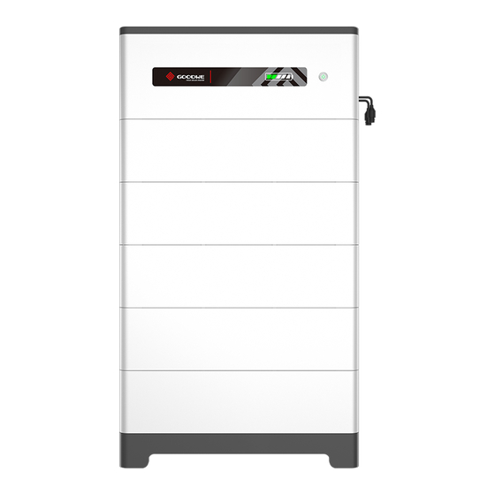
Page 13: Appearance
User Manual V1.3-2022-08-20 04 Check and Storage 3.3 Appearance Battery system appearance NOTICE • Ensure that the PCU is installed above the battery modules. Do not install any battery modules above the PCU. • This manual will show you the installation and electrical connection of 5 battery modules. - Page 14 04 Check and Storage User Manual V1.3-2022-08-20 Power control unit appearance Left View Right View Front View Bottom View Communication terminal DC terminal (BAT) Ventilation valve (COM) Grounding point Air switch 6. SOC indicator Multifunction button Battery serial connection indicator interface [1].
-
Page 15: Dimensions
User Manual V1.3-2022-08-20 05 System Installation 3.4 Dimensions 70mm... -
Page 16: Check And Storage
05 System Installation User Manual V1.3-2022-08-20 4 Check and Storage 4.1 Check Before Receiving Check the following items before receiving the product. 1. Check the outer packing box for damage, such as holes, cracks, deformation, and other signs of equipment damage. Do not unpack the package and contact the supplier as soon as possible if any damage is found. -
Page 17: Storage
User Manual V1.3-2022-08-20 05 System Installation Power control unit Expansion Normal locking Base x 1 DC connector x 1 PCU x 1 bolt x 4 bracket x N Grounding M5 hexagon M6 screw x 2 Terminal resistor x 1 M5*12 screw x 4 terminal x 2 screw x 2 Adjustable... -
Page 18: System Installation
05 System Installation User Manual V1.3-2022-08-20 5 System Installation 5.1 Installation Requirements Installation Environment Requirements 1. Do not install the equipment in a place near flammable, explosive, or corrosive materials. 2. Do not install the equipment in a place that is easy to touch, especially within children’s reach. High temperature exists when the equipment is working. - Page 19 User Manual V1.3-2022-08-20 05 System Installation Mounting Support Requirements • The mounting support shall be nonflammable and fireproof. • Install the equipment on a surface that is solid enough to bear the product weight. • Put the battery system near the wall and install the locking brackets to prevent the battery from falling down.
-
Page 20: Installing The Battery System
05 System Installation User Manual V1.3-2022-08-20 5.2 Installing the Battery System 5.2.1 Moving the Equipment CAUTION • Operations such as transportation, turnover, installation and so on must meet the requirements of the laws and regulations of the country or region where it is located. •... - Page 21 User Manual V1.3-2022-08-20 05 System Installation Installing the Battery System (Without Adjustable Feet) Step 1: Install the locking brackets to the base. Step 2: Place the base cling to the wall and mark the drilling positions. Then remove the base. Step 3: Drill holes using the hammer drill.
- Page 22 05 System Installation User Manual V1.3-2022-08-20 Installing the Battery System (With Adjustable Feet) Step 1: Install the adjustable feet to the base. Step 2: Install the locking brackets to the base. Step 3: Place the base cling to the wall and mark the drilling positions. Then remove the base. Step 4: Drill holes using the hammer drill.
-
Page 23: Installing The Power Control Unit
User Manual V1.3-2022-08-20 05 System Installation 5.2.3 Installing the Power Control Unit NOTICE • Cover the equipment with a cardboard to prevent foreign matters when drilling holes. • Put the locking bracket of the PCU cling to the wall, and ensure that the bottom of the PCU is vertically and closely put on the battery. - Page 24 05 System Installation User Manual V1.3-2022-08-20 Diameter: 10mm Depth: 80mm...
-
Page 25: Electrical Connection
User Manual V1.3-2022-08-20 06 Electrical Connection 6 Electrical Connection 6.1 Safety Precaution DANGER • The battery system exists high voltage during the equipment running. Please keep Power Off before any operations to avoid danger. Strictly follow all safety precautions outlined in this manual and safety labels on the equipment during the operation. -
Page 26: Electrical Connection
06 Electrical Connection User Manual V1.3-2022-08-20 6.2 Electrical Connection NOTICE • A max of eight battery systems can be parallel connected in one energy storage system. Ensure that the usable energy of each battery system is the same. • Install the terminal resistor to the COM3 port of Battery system 1, which is connected to the inverter directly. -
Page 27: Connecting The Pe Cable
User Manual V1.3-2022-08-20 06 Electrical Connection 6.3 Connecting the PE cable NOTICE • Connect the PE cable first before installing the equipment. Disconnect the PE cable before dismantling the equipment. • The drawing force of the cable after crimping should be at least 400N. •... - Page 28 06 Electrical Connection User Manual V1.3-2022-08-20 Connecting the power cable (Type 1) Crimping length: 7.5±0.2mm Crimping hight: 7.5±0.2mm Cross-sectional area of the power cable S: 14mm ≤S≤16mm NOTICE • Recommended tool: manual hydraulic press plier. Crimping hight: 7mm; moulding: 16mm •...
- Page 29 User Manual V1.3-2022-08-20 06 Electrical Connection Cross-sectional area of the power cable S: 4mm ≤S≤6mm NOTICE • Replace the white seal ring inside the power connector with a black seal ring (inner diameter 4.59mm) before crimping the power cable. • Make sure the conductor cut is flat after folding in half. •...
- Page 30 06 Electrical Connection User Manual V1.3-2022-08-20 Connecting the power cable (Type 2) NOTICE • The drawing force of the cable after crimping should be at least 1200N when the cross- sectional area range of the cable is 14mm ≤S≤16mm • The drawing force of the cable after crimping should be at least 500N when the cross- sectional area range of the cable is 4mm ≤S≤6mm Click...
-
Page 31: Connecting The Communication Cable
User Manual V1.3-2022-08-20 06 Electrical Connection 6.5 Connecting the Communication Cable NOTICE • The two battery communication ports have the same function. • Connect the cable to any one of the two communication ports. And connect the terminal resistor to the other port. •... - Page 32 06 Electrical Connection User Manual V1.3-2022-08-20 Step 1: Disassemble the waterproof module. Step 2: Run the communication cable through the waterproof module. Step 3: Connect the communication cable to the battery. Tighten the waterproof module.
-
Page 33: Connecting The Terminal Resistor
User Manual V1.3-2022-08-20 06 Electrical Connection 6.6 Connecting the Terminal Resistor NOTICE If the terminal resistor is not installed, the Interlock Failure will occur, and the system cannot work correctly. Step 1: Disassemble the waterproof module. Step 2: Install the terminal resistor. Step 3: Tighten the waterproof module. -
Page 34: Installing The Protection Cover
06 Electrical Connection User Manual V1.3-2022-08-20 6.7 Installing the Protection Cover... -
Page 35: System Operation
User Manual V1.3-2022-08-20 07 Equipment Commissioning 7 System Operation 7.1 Check Before Power ON Check the following items before power on to avoid the battery system being damaged. Check Item The inverter is firmly installed in a clean place where is well-ventilated and easy to operate. - Page 36 07 Equipment Commissioning User Manual V1.3-2022-08-20 Parallel Connected Battery System Step 1: (Optional) Turn on the breaker between the inverter and the battery system. Step 2: Turn on the breakers between the battery systems. Step 3: Turn on the air switches of the battery systems in turn. Step 4: Turn on the inverter in the system following the instructions in the user manual of the inverter.
-
Page 37: Setting The Battery Parameters
PV Wi-Fi SSID: Solar-WiFi*** Master Password: 12345678 Set battery model via the PV Master app. Select Battery Model GoodWe Select LX F-H. LX F-H PYLON AlpahESS eSTORE DYNESS NOTICE "Battery Communication Failure" will be displayed if you select the wrong battery model. Please... -
Page 38: Indicator Status
07 Equipment Commissioning User Manual V1.3-2022-08-20 7.4 Indicator Status SOC Indicator Button Indicator Button Indicator Status Green Standby or Working Alarming or Faulty 7.4.1 Normal Status Button Indicator SOC Indicator Description SOC<5% 5%≤SOC<25% Idle: green light 25%≤SOC<50% double blink Standby: green light single blink 50%≤SOC<75% Working: steady green... -
Page 39: Alarming Status
User Manual V1.3-2022-08-20 07 Equipment Commissioning 7.4.2 Alarming Status Button SOC Indicator Alarm Solutions Indicator Battery Restart the battery. If the problem persists, Overvoltage please contact the after-sales service. Long press the button for 5 seconds to start Battery the battery under charging conditions. If Undervoltage the problem persists, contact the after-sales service. -
Page 40: Faulty Status
07 Equipment Commissioning User Manual V1.3-2022-08-20 7.4.3 Faulty Status Button SOC Indicator Fault Solutions Indicator Restart the battery. If the problem Battery persists, please contact the after-sales Overvoltage service. Long press the button for 5 seconds Battery to start the battery under charging Undervoltage conditions. -
Page 41: Power Off The Battery System
User Manual V1.3-2022-08-20 07 Equipment Commissioning Restart the battery. If the problem Air Switch Fault persists, please contact the after-sales service. Do not touch the batteryand contact Insulation Fault the after-sales service. Power off and check the Internal communication cables. Restart the Communication battery. -
Page 42: Maintenance
08 Maintenance User Manual V1.3-2022-08-20 8 Maintenance 8.1 Power OFF the Battery System DANGER • Power off the battery system before operations and maintenance. Otherwise, the equipment may be damaged or electric shocks may occur. • Push the air switch to restart the battery. Follow the steps below to power off the battery system to prevent the system from being damaged. -
Page 43: Parameters
User Manual V1.3-2022-08-20 09 Technical Parameters 9 Parameters Technical Parameters LX F6.6-H LX F9.8-H LX F13.1-H LX F16.4-H Usable Energy(kWh)* 6.55 9.83 13.1 16.38 Battery Module LX F3.3-H: 38.4V 3.27kWh Number of Modules Cell Type LFP(LiFePO4) Cell Configuration 64S1P 96S1P 128S1P 160S1P Nominal Voltage (V) - Page 44 Official PV Master App Website GoodWe Technologies Co.,Ltd. No. 90 Zijin Rd., New District, Suzhou, 215011, China www.goodwe.com service@goodwe.com Contact Information...
Need help?
Do you have a question about the Lynx Home F Series and is the answer not in the manual?
Questions and answers