Goodwe Lynx Home U Series User Manual
Lv
Hide thumbs
Also See for Lynx Home U Series:
- Quick installation manual (94 pages) ,
- User manual (28 pages) ,
- Quick installation manual (4 pages)
Table of Contents
Advertisement
Advertisement
Table of Contents

Related Manuals for Goodwe Lynx Home U Series


Summary of Contents for Goodwe Lynx Home U Series
- Page 1 Lynx Home U Series (LV) User Manual Ver 1.0 2021-3-30...
- Page 2 Disclaimer • All the information in this document is the property of GoodWe. No part of this document could be reproduced in any way for business use. Internal use is allowed. • GoodWe makes no representations or warranties express or implied, with respect to this document or any of the equipment and/or software it may describe, including (with no limitation) any implied warranties of utility, merchantability, or fitness for any particular purpose. All such representations or warranties are expressly disclaimed. Neither GoodWe nor its distributors or dealers shall be liable for any indirect, incidental, or consequential damages under any circumstances.
-
Page 3: Table Of Contents
TABLE OF CONTENTS 01 Safety Precaution ..............1 02 Product Introduction ............2 2.1 Product Description ..................2 2.2 Symbol Description ..................2 03 Battery Introduction ............3 3.1 Appearance ......................3 3.2 Dimensions ......................4 04 Storage and Package ............5 4.1 Storage Environment ..................5 4.2 Packing List ......................5 05 System Installation .............. 6 5.1 Installation Environment ................6 5.2 Mounting Space Requirements ..............6 5.2.1 Floor Mounting Space Requirements . -
Page 4: Safety Precaution
01 Safety Precaution DANGER! • Please keep Power Off before any operations to avoid danger. Strictly follow all safety precautions outlined in this manual and safety labels on the equipment. • All installation operations should be performed by trained and knowledgeable technical personnel who are familiar with local standards and electric systems. • Do not use the battery if it is defective, broken, or damaged. • Do not disassemble, modify, or replace any part of the battery without official authorization from GoodWe. • Damaged battery may leak electrolyte. Do not contact with the liquid leakage or volatile matter. Please contact GoodWe Technical Support for help immediately. WARNING! • Anyone contact the leaked substance accidently has to do as following: • Breath in the leaked substance: Evacuate from the polluted area, and seek immediate medical assistance. • Eye contact: Rinse your eyes for at least 15 minutes with clean water and seek immediate medical assistance. -
Page 5: Product Introduction
02 Product Introduction 2.1 Product Description • This manual introduces Lynx Home U Series ( LV) Battery System (hereinafter referred to as the Battery System), including the product introduction, application, installation, commission, and technical parameters, etc. • The Battery System can match with GOODWE ES、 EM、 SBP、 BP series inverters. • At most 6 batteries can be connected in this Battery System. 2.2 Symbol Description Symbol Description A potential hazard exists when the equipment is working. Wear personal protective equipment during operation. -
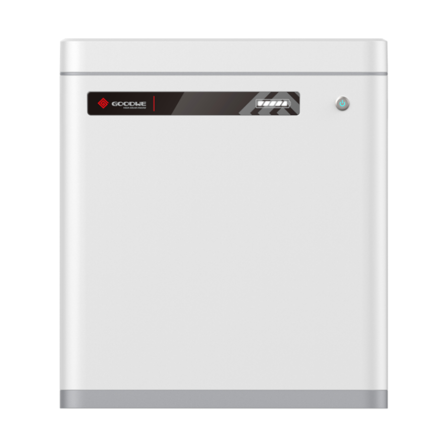
Page 6: Battery Introduction
03 Battery Introduction 3.1 Appearance Parts Description Remaining power display; indicates the battery SOC Indicator state together with the button indicator. Switch Button Switch on/off the battery Green and red light; indicates the battery state Button Indicator together with the SOC indicator Grounding Teminal Grounding Protection Negative Pole of the Battery Power transmission Positive Pole of the Battery Power transmission CAN COM Port Communication transmission Circuit-Breaker Short circuit/break protection... -
Page 7: Dimensions
3.2 Dimensions 570mm 175mm 505mm Front View Side View 124mm 124mm 285mm Wall Mounting Plate... -
Page 8: Storage And Package
04 Storage and Package 4.1 Storage Environment If the equipment is not to be installed or used immediately, please ensure that the storage environment meets the following requirements: • Pack the equipment using a packing box and put some desiccant in the box before sealing. • Put the equipment back to the packing box if it is not to be installed in 3 days after unpacking. • Storage SOC: 25%~50%SOC. Charge and discharge the battery every 3 months. • Recommended storage temperature: -20℃~40℃(less than one month) or 0℃~35℃(less than one year). • Recommended storage humidity: 0%~95%RH(no condensation). Do not install the battery if any moist or condensation is found. • Place the quipment in a cool place where away from direct sunlight. • Keep the equipment away from inflammable, explosive, and corrosive matters. • Keep the equipment away from the rain. 4.2 Packing List • Check outer packing for damage and model before unpacking it. If you find any damage or the model is not what you requested, do not unpack the product and contact the after-sales service as soon as possible. • Check whether the deliverables are intact and complete first after unpacking the battery.If anything wrong, contact the after-sales service as soon as possible. Wall Mounting Anti-dumping Wire Harness Fix Battery x 1 Plastic Cover x1... -
Page 9: System Installation
05 System Installation 5.1 Installation Environment • Install the Battery System on the ground with sufficient bearing capacity and flatness. Increase the bearing capacity and flatness of the ground by laying the foundation, adding bearing plates and so on. • The optimal temperature for the battery is 20~40℃. • Avoid exposing the equipment to direct sunlight or rain. • Install the equipment away from heat/cold source. • Do not install the equipment in the place where the temperature changes extremely. • Install the equipment away from strong interferences to ensure its regular work. • Keep children away from the equipment. • Do not install the equipment in places prone to accumulate water. • Do not put inflammable or explosive matters near the equipment. 5.2 Mounting Space Requirements 5.2.1 Floor Mounting Space Requirements The space between the left and the right battery is a recommened distance. Keep the distance as short as you can if there is no influence to the operation. -
Page 10: Wall Mounting Space Requirements
5.2.2 Wall Mounting Space Requirements The space between the left and the right battery is a recommened distance. Keep the distance as short as you can if there is no influence to the operation. Single Row Installation ≥300mm ≤1500mm BAT 1 BAT 2 BAT 6 .. -
Page 11: System Installation
5.3 System Installation • If multi batteries are to be connected, check and select batteries with similar production date. • Strictly follow the warnings on the outer package, which shows you the right direction for placing. 5.3.1 Package Removing 1. Unpack the carton and take the accessory bag out. 2. Pull the carton upwards to remove it. 3. Take out the wall mounting plate. 4. Hold the battery handle to take the battery out. -
Page 12: Floor Mounting
5.3.2 Floor Mounting Make sure that the floor is flat and horizontal. Install the anti-dumping bracket on both sides. 1.Screw the anti-dumping bracke on the battery. 2.Align the battery and the wall, then put the anti-dumping bracket close to the wall. Mark the drilling position and remove the battery. 3.Drill a hole on the wall using the driller. Hole diameter 10mm and depth 80mm. 4.Fix the expansion bolts, tightening torque: 10N·m. 2 N·M 5.3.3 Wall Mounting Wall mounting needs to be done by two persons. 1. Mark the drilling position using the wall mounting plate and level using a spirit level. 2. Place the wall mounting plate close to the wall firmly, mark the drilling position and remove the wall mounting plate. 3. Drill a hole on the wall using the driller. Hole diameter 13mm and depth 65mm. 4. Fix the M10 expansion bolts, tightening torque: 10N·m. If the bubble of the spirit level is within the dashed lines, then the plate is horizontal. -
Page 13: Cable Connection
4. Lift the battery parallel to the ground. 5. Hang the upper part of the battery on the wall mounting plate. 6. Push the bottom part of the battery to the slot. 5.3.4 Cable Connection Overview of the cable connection Take SBP series as an example here. Terminal Resistance SYSTEM BACK-UP BATTERY Wi-Fi Reset/Reload 2 0 1 9 GRID ENERGY Wi-Fi FAULT COM PORT COM PORT COM PORT COM PORT ..Battery 1 Battery 2 Battery 6 Power Cable Power Cable... - Page 14 Ground Cable Connection • Connect the PE cable first before installing the equipment. Disconnect the PE cable before dismantling the equipment. • The drawing force of the cables after crimping is at least 400N. • Connect any one of the two ground cables to the ground. Reserve the other ground cable. • The cross-sectional area of the PE cable conductor: 5mm . The cable should meet standards for outdoor use. 1. Crimp the ground terminal. L2=L1+(1~2)mm 2. Connect the ground cable to the battery. 2 N·M...
- Page 15 Power Cable Connection • Connect the red power cable to the red wire harness, and the black power cable to the black wire harness. The cross-sectional area of the crimping part is 25mm². • Withstand Voltage: DC1500V; Temperature: -40℃~200℃. • Stripped conductor length: 18±1mm. • Secure the back shell and check whether there is any gap. • Recommended tool: manual hydraulic press plier(mould:25mm²) • Drawing force after crimping≥1200N. • If a single battery is applied, you are suggested to connect any one of the two power ports and cover the other port using the protective cover. • Connect power cables between multi batteries in parallel, which means connect postive pole of one battery to the positive pole of the next battery, and negative pole to negative pole. Cover and protect the reserved power port of the last battery. • The power cable between the batteries should be as short as it can be and meet installation requirements. Length: 7.5±0.2mm Height:7.5±0.2mm 1. Crimp the power cable. 2. Put the rubber seal ring. 3. Secure the back shell. 4. Connect the power cable. Click...
- Page 16 Communication Cable Connection The two communication cables are the same. • Do not use RJ45 cable with protective cover. • When one battery is applied, connect one communication cable to the inverter by RJ45 connector and connect the other cable to the terminal resistance. • When multiple batteries are applied, connect the communication ports in series using net cables. Connect one communication cable of the last battery to the terminal resistance. 1. Remove the waterproof module. 2. Route the cable through the waterproof module. 3. Crimp the RJ45 Registered Jack. 4. Secure the back cover. RJ45 Registered Jack CAN COM Port Definition CAN_H CAN_L 1,2,3,6,7,8...
-
Page 17: Install The Wire Harness Fix Bar
5. Connect the communication cable and the terminal resistance to the battery. 6. Secure the cover. 5.3.5 Install the Wire Harness Fix Bar 1. Put the wire harness on the corresponding slot. 2. Install the bar using M5 screws. 2 N·M... -
Page 18: System Operation
06 System Operation 6.1 Check Before Power On Check the following items before power on. Otherwise, the Battery System may be damaged. Items The equipment is installed firmly in a place where is convenient for operation and maintenance. The installation place is clean and well ventilated. The ground cable, power cable, communication cable and terminal resistance are connected correctly and securely. -
Page 19: Indicator Status
6.4 Indicator Status Button Indicator SOC Indicator Button Indicator Status Green Light Standby、 Working、 Alert Red Light Faulty 6.4.1 Normal State Button Indicator SOC Indicator Description SOC<5% 5%≤SOC<25% 25%≤SOC<50% Standby: green light blinking for 1s Working: green light on 50%≤SOC<75% 75%≤SOC<95% SOC≥95%... -
Page 20: Alerting
6.4.2 Alerting Button SOC Indicator Alerting Solutions Indicator Temperature Exception Power off and restart after 2 hours.If the problem persists, please contact GoodWe. High Temperature Power off and Wait for the temperature to Low Temperature increase. Restart the battery. If the problem Discharging persists, please contact GoodWe. Overcurrent when Charging Green light Restart the battery. If the problem persists, Overcurrent When blingking for 3s please contact GoodWe. Discharging Overvoltage Press the button consecutively for 5 times Under voltage in 10s if you can charge the battery. The voltage will recover to normal. Power off and Wait for the temperature to Low Temperature increase. Restart the battery. If the problem Charging persists, please contact GoodWe. • Restart the battery by pressing the switch button. • If the batteries power off under undervoltage protection and multiple batteries are connected, just press the button of any one battery consecutively for 5 times to activate them. -
Page 21: Power Off
6.5 Power Off Please follow the steps to power off the Battery System, otherwise, the System may be damaged. 1. Press the switch button for at least 5s until the indicator lights off. Press the button of any one battey if multi batteries are connected. 2. Turn off the Circuit-Breaker. 3. Make sure that the SOC indicator of the battery is off. 6.6 Install the Plastic Cover • Ensure that the battery can work normally before installing the cover. • Do not press the cables during installation. 1. Install the plastic cover. 2. Push the snap of the cover into the slot. -
Page 22: Technical Parameters
07 Technical Parameters Technical Data LX U5.4-L 2*LX U5.4-L 3*LX U5.4-L 4*LX U5.4-L 5*LX U5.4-L 6*LX U5.4-L Rated Energy (kWh)* 5.4 kWh 10.8 kWh 16.2 kWh 21.6 kWh 27 kWh 32.4 kWh Usable Energy (kWh)* 4.8 kWh 9.6 kWh 14.4 kWh 19.2 kWh 24 kWh 28.8 kWh Cell Type LFP (LiFePO4) Cell Configuration 16S1P 16S2P 16S3P 16S4P 16S5P 16S6P Rated Voltage (V) 51.2 V... -
Page 23: Maintenance
08 Maintenance Item Period Fully charge the battery and discharge it to 25~50% if the battery Once Every 3 months is not in use. Check the wall mounting plate, fix it if it is not secured. Once Every 6 months Check whether the outer shell is broken. Repair the painting or Once Every 6 months contact after-sales service if there is any broken. Check whether there is an exposed cable. Replace the exposed Once Every 6 months cable or contact after-sales service for help. Check whether there is debris accumulation around the battery Once Every 6 months to avoid affecting heat dissipation. Check for water and pest to avoid prolonged intrusion. Once Every 6 months • Please contact after-sales for help if you find any problems that may influence the battery or the inverter. Disassemble without permission is WARNING! strictly forbidden. • Please contact after-sales for help if the conductive wire is exposed because high voltage danger exists. Do not touch or disassemble privately. • In case of other emergencies, contact the after-sales as soon as possible. Please operate following the guidance of the after-sales, or just wait for the after-sales service operators. Remove the Plastic Cover Gently pry up two clips on one side using a screwdriver to remove the plastic cover. - Page 24 PV Master APP SEMS Portal APP SEMS Portal website LinkedIn GoodWe www.semsportal.com Offical Website JIANGSU GOODWE POWER SUPPLY TECHNOLOGY CO.,LTD No. 90 Zijin Rd., New District, Suzhou, 215011, China www.goodwe.com service@goodwe.com...
Need help?
Do you have a question about the Lynx Home U Series and is the answer not in the manual?
Questions and answers