Goodwe Lynx Home U Series User Manual
Rechargeable lithium ion battery system
Hide thumbs
Also See for Lynx Home U Series:
- User manual (24 pages) ,
- Quick installation manual (94 pages) ,
- Quick installation manual (20 pages)

Related Manuals for Goodwe Lynx Home U Series


Summary of Contents for Goodwe Lynx Home U Series
- Page 1 User Manual Rechargeable Lithium Ion Battery System Lynx Home U Series V 1.3-2022-08-30...
- Page 2 Disclaimer User Manual V1.3-2022-08-30 Disclaimer • All the information in this document is the property of the manufacturer. No part of this document could be reproduced in any way for business use. Internal use is allowed. • The manufacturer makes no representations or warranties express or implied, with respect to this document or any of the equipment and/or software it may describe, including(with no limitation) any implied warranties of utility, merchantability, or fitness for any particular purpose.
-
Page 3: Table Of Contents
Content User Manual V1.3-2022-08-30 TABLE OF CONTENTS 01 Safety Precaution ............... 01 02 Product Introduction ..............03 2.1 Product Description ..................03 2.2 Symbol Description ..................03 03 Battery Introduction ..............04 3.1 Appearance ....................04 3.2 Dimensions ....................04 04 Storage and Package .............. -
Page 4: Safety Precaution
01 Safety Precaution User Manual V1.3-2022-08-30 01 Safety Precaution DANGER • Please keep Power Off before any operations to avoid danger. Strictly follow all safety precautions outlined in this manual and safety labels on the equipment. • All installation operations should be performed by trained and knowledgeable technical personnel who are familiar with local standards and electric systems. - Page 5 • Restrictions of Hazardous Substances Directive 2011/65/EU and (EU) 2015/863 (RoHS) • Waste Electrical and Electronic Equipment 2012/19/EU • Registration, Evaluation, Authorization and Restriction of Chemicals (EC) No 1907/2006 (REACH) You can download the EU Declaration of Conformity on https://en.goodwe.com.
-
Page 6: Product Introduction
User Manual V1.3-2022-08-30 02 Product Introduction 2.1 Product Description • This manual introduces Lynx Home U Series(LV) Battery System (hereinafter referred to as the Battery System), including the product introduction, application, installation, commission, and technical parameters, etc. • At most 6 batteries can be connected in this Battery System. -
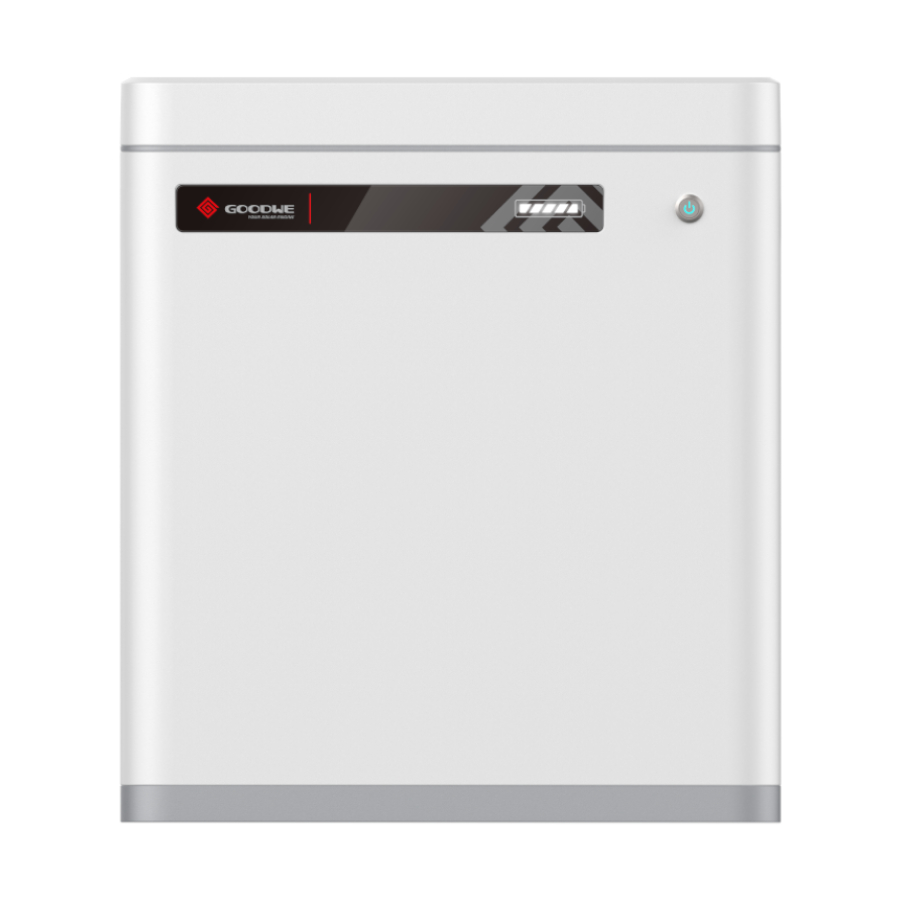
Page 7: Battery Introduction
03 Battery Introduction User Manual V1.3-2022-08-30 03 Battery Introduction 3.1 Appearance Parts SOC Indicator Switch Button Button Indicator Grounding Teminal Power Cable Port CAN COM Port Ventilation Valve Circuit-Breaker 3.2 Dimensions... -
Page 8: Storage And Package
04 Storage and Package User Manual V1.3-2022-08-30 04 Storage and Package 4.1 Storage Environment If the equipment is not to be installed or used immediately, please ensure that the storage environment meets the following requirements: • Pack the equipment using a packing box and put some desiccant in the box before sealing. •... -
Page 9: System Installation
05 System Installation User Manual V1.3-2022-08-30 05 System Installation 5.1 Installation Environment • Install the Battery System on the ground with sufficient bearing capacity and flatness. Increase the bearing capacity and flatness of the ground by laying the foundation, adding bearing plates and so on. - Page 10 05 System Installation User Manual V1.3-2022-08-30 Mounting Support Requirements • The mounting support shall be nonflammable and fireproof. • Install the equipment on a surface that is solid enough to bear the product weight. • Put the battery system near the wall and install the locking brackets to prevent the battery from falling down Installation Angle Requirements •...
-
Page 11: System Installation
05 System Installation User Manual V1.3-2022-08-30 5.3 System Installation NOTICE If multi batteries are to be connected, check and select batteries with similar production date and a same cell grade. 5.3.1 Floor Mounting Step1 Screw the anti-dumping bracke on the battery. Step2 Align the battery and the wall, then put the anti-dumping bracket close to the wall. -
Page 12: Wall Mounting
05 System Installation User Manual V1.3-2022-08-30 5.3.2 Wall Mounting NOTICE Wall mounting needs to be done by two persons. Step1 Place the wall mounting plate close to the wall firmly, mark the drilling position and remove the wall mounting plate. Step2 Drill a hole on the wall using the driller. -
Page 13: Cable Connection
05 System Installation User Manual V1.3-2022-08-30 5.3.3 Cable Connection Overview of the cable connection Take SBP series as an example here. Terminal resistor 2≤N≤6 Battery 1 Battery 2 Battery N Power Cable Power Cable Ground Standard for Positive for Negative Cable Net Cable Pole... - Page 14 05 System Installation User Manual V1.3-2022-08-30 Power Cable Connection NOTICE • Connect the red power cable to the red wire harness, and the black power cable to the black wire harness. The cross-sectional area of the crimping part is 25mm². •...
- Page 15 05 System Installation User Manual V1.3-2022-08-30 Communication Cable Connection NOTICE The two communication cables are the same. • Do not use RJ45 cable with protective cover. • When one battery is applied, connect one communication cable to the inverter by RJ45 connector and connect the other cable to the terminal resistance.
-
Page 16: Install The Wire Harness Fix Bar
05 System Installation User Manual V1.3-2022-08-30 Installing the terminal resistor 5.3.4 Install the Wire Harness Fix Bar... -
Page 17: System Operation
06 System Operation User Manual V1.3-2022-08-30 06 System Operation 6.1 Check Before Power On Check the following items before power on. Otherwise, the Battery System may be damaged. Items The equipment is installed firmly in a place where is convenient for operation and maintenance. - Page 18 06 System Operation User Manual V1.3-2022-08-30 Single battery Inverter Battery DC Breaker (Only for Australia ) Parallized batteries Inverter DC Breaker (Only for Australia ) 2≤N≤6 DC Breaker (Only for Australia ) Battery N Battery1 Battery2...
-
Page 19: Battery Parameter Settings
06 System Operation User Manual V1.3-2022-08-30 6.3 Battery Parameter Settings Select the right options on PV Master after connecting the battery and the inverter. APP Installatin and Connection: Connect the smartphone Download with the inverter. and Install Wi-Fi SSID: Solar-WiFi** PV Master Passwaord: 12345678 Select the battery model on PV Master:... -
Page 20: Normal State
Alerting Solutions Indicator Temperature Exception Power off and restart after 2 hours.If the problem persists, please contact GoodWe. High Temperature Power off and Wait for the temperature to Low Temperature increase. Restart the battery. If the problem Discharging persists, please contact GoodWe. -
Page 21: Faulty
SOC Indicator Fault Solution Indicator Temp. sensor failure Restart the battery. If the problem persists, please contact GoodWe for help. MOS Failure Circuit-Breaker Turn on the Circuit-Breaker.If the problem Failure persists, please contact GoodWe. Power off and check the communication cable. -
Page 22: Indicator Status(Lx U5.4-20)
06 System Operation User Manual V1.3-2022-08-30 6.5 Indicator Status(LX U5.4-20) SOC Indicator Button Indicator Button Indicator Status Green Light Standby, Working Red Light Alert, Faulty 6.5.1 Normal State Button Indicator SOC Indicator Description ﹤ 5%≤SOC ﹤ Idle: green light blink 2 times in 1 second 25%≤SOC ﹤... -
Page 23: Faulty
GoodWe for help. MOS Short-Circuit Fault Parallized Check the battery model. If the battery model Connection Fault is not correct, please contact GoodWe. Communication Fault Restart the battery. If the problem persists, please contact GoodWe for help. MCU Internal... -
Page 24: Power Off
06 System Operation User Manual V1.3-2022-08-30 Restart the battery. If the problem persists, Precharge Failure please contact GoodWe for help. Power off for 2 hours.If the problem persists, Overtemperature please contact GoodWe. Fault Steady red Current Sensor Power off for 2 hours.If the problem persists, Overtemperature please contact GoodWe. -
Page 25: Technical Parameters
07 Technical Parameters User Manual V1.3-2022-08-30 07 Technical Parameters Technical Data LX U5.4-L 2*LX U5.4-L 3*LX U5.4-L 4*LX U5.4-L 5*LX U5.4-L 6*LX U5.4-L Rated Energy (kWh)*1 10.8 16.2 21.6 32.4 Usable Energy (kWh)*2 14.4 19.2 28.8 Cell Type LFP(LiFePO4) Cell Configuration 16S1P 16S2P 16S3P... - Page 26 07 Technical Parameters User Manual V1.3-2022-08-30 Technical Data LX U5.4-20 2*LX U5.4-20 3*LX U5.4-20 4*LX U5.4-20 5*LX U5.4-20 6*LX U5.4-20 Usable Energy (kWh) 5.4 kWh 10.8 kWh 16.2 kWh 21.6 kWh 27 kWh 32.4 kWh Cell Type LFP(LiFePO4) Cell Configuration 16S1P 16S2P 16S3P...
-
Page 27: Maintenance
08 Maintenance User Manual V1.3-2022-08-30 08 Maintenance Item Period Fully charge the battery and discharge it to 25~50% if the Once Every 3 months battery is not in use. Check the wall mounting plate, fix it if it is not secured. Once Every 6 months Check whether the outer shell is broken. - Page 28 GoodWe Technologies Co., Ltd. No. 90 Zijin Rd., New District, Suzhou, 215011, China www.goodwe.com service@goodwe.com Local Contacts...
Need help?
Do you have a question about the Lynx Home U Series and is the answer not in the manual?
Questions and answers