Table of Contents
Advertisement
Quick Links
Advertisement
Table of Contents

Subscribe to Our Youtube Channel
Related Manuals for OSS 4UP 10-SLOT GEN4


Summary of Contents for OSS 4UP 10-SLOT GEN4
- Page 1 4UP 10-SLOT GEN4 INSTALLATION GUIDE 4UP 10-SLOT Gen4 www.onestopsystems.com...
-
Page 2: Table Of Contents
One Stop Systems Table of Contents General Specifications ..............................5 Features ........................................6 4UP Architecture (10 Slot) ..................................6 PCIe Slots ........................................7 Backplane Block Diagram ..................................7 Dimensions........................................ 8 Parts Overview ......................................9 HIB x16 Gen 4 Card ....................................11 Backplane ........................................ - Page 3 One Stop Systems 11.3 Verify Adapter Card LEDs ................................... 35 11.4 Adapter Card LED Definitions ................................36 11.5 Slot LEDs ......................................36 11.6 Power Distribution Board LED ................................37 11.7 Front LED ......................................37 11.8 Power Supply LED Indicator ................................38 Software Installation ..............................39 12.1 Software Driver Installation ................................
- Page 4 My PCIe devices are showing UP with a Yellow Exclamation mark ....................66 17.3 No link between host and target cards .............................. 66 17.4 Broken OSS-Backplane ..................................66 17.5 My PCIe cards are not detected ................................. 67 How to Get More Help ..............................67 18.1...
-
Page 5: General Specifications
2x PCIe x4 x16 Host-to-Target uplinks (64GB/s) 4x PCIex4 x16 Host-to-Target uplinks (128 GB/s) SmartNIC Host Backplane Options Single OSS-538: • 1x single-width PCIe 4.0 x 16 FHFL upstream slot • 4x dual-width PCIe 4.0 x16 FHFL downstream slots Dual OSS-538: •... -
Page 6: Features
One Stop Systems Features - PCIe Gen4 architecture - Semi-rugged frame design - Dynamic fan speed control - Configurable slot and host uplinks to optimize throughput - Integrated IPMI based system monitoring - AC and DC power inlet options 4UP Architecture (10 Slot) 4U Pro 10 Slot... -
Page 7: Pcie Slots
One Stop Systems PCIe Slots Slot Type: Closed-ended PCIe slot / connector, all the slots are x16 mechanical. • Six x8 electrical slots (slots 1, 2, 3, 4, 5 and 6) • Three x16 electrical slots(slots 0, 7 and 8) Backplane Block Diagram 4U Pro 10 Slot... -
Page 8: Dimensions
One Stop Systems Dimensions 4U Pro 10 Slot... -
Page 9: Parts Overview
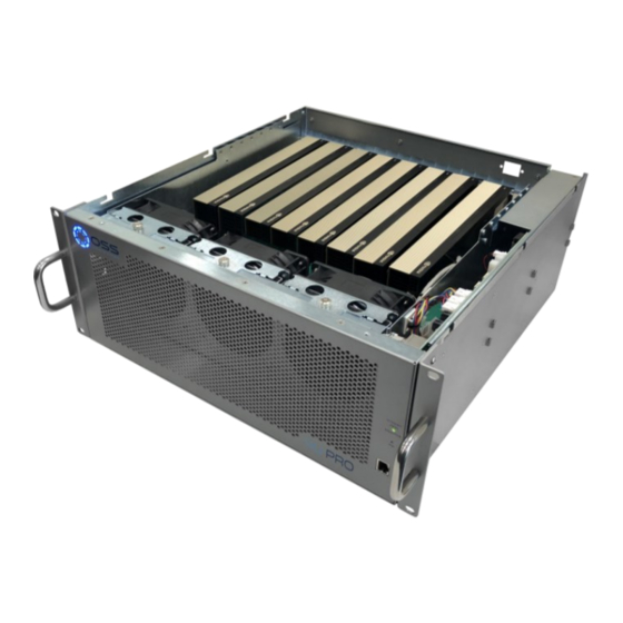
Power Supply Modules Removable Fans Target Cards RearRJ45 Port - Access to IPMI Number Description IPMI Module/Board Fan Power Connectors Auxiliary Power Connectors (10 qty) Power Supply Housing Backplane (OSS-538 board) Passive Heatsink / PCIe Switch ARF Connectors 4U Pro 10 Slot... - Page 10 One Stop Systems Number Description 12V Input Power Connectors Upstream Slots/Target Slots Downstream Slot/ PCIe Card Slots Options Slots (Operates as either Downstream or Upstream depending on the configuration) 4U Pro 10 Slot...
-
Page 11: Hib X16 Gen 4 Card
One Stop Systems HIB x16 Gen 4 Card x4 cable Ports There are four x4 cable ports /connectors available on the HIB Gen4 card. Port #0 is located nearest to the Link LED. • A single x4 SFF-8644 cable must be inserted into port#0 of the Target card. •... -
Page 12: Backplane
One Stop Systems Backplane Item Name Description 12V Input Power 12V input power for the 538 board. Not to be used for external GPU aux. ARF 6 Top Connectors For connecting ARC 6 cables between ”Option slot” and PEX switch I2C and temp sensors interface Connector for I2C and temp sensors interface to the power backplane Ethernet port... -
Page 13: Slot Configurations
One Stop Systems Slot Configurations Configuration# 1: Default slot configuration. One Upstream slot and five Downstream slots. You must have the ARC6 cables attached between the edge of the board and the slot connectors under the backplane. Without those ARC6 cables nothing will work in SLOT 5. - Page 14 One Stop Systems Configuration# 3: Two backplanes are daisy chained together 1 Upstream Slot 9 Downstream slots 2 Non-oPerational slots 4U Pro 10 Slot...
-
Page 15: Use Case Diagrams
Configuration 1 OSS-538 backplane is linked to a single host computer. • Four x4 link cables are connected between OSS Gen4 Host card and Target card. 5 Downstream slots • 5 x16 slots (Slot 1, 2, 3, 4 and 5) Configuration 2 OSS-538 backplane is linked to two host computers, see diagram below. - Page 16 One Stop Systems Configuration 3 Two OSS-538 backplanes are daisy chained together and it is linked to a single host computer. • 9 Downstream slots 1st backplane: 4 downstream slots • 4 x16 slots (slot 1, 2, 3 and 4) •...
-
Page 17: Getting Started
Unit front power LED Power supplies LED Check the OSS devices via operating system, verifying all OSS devices are properly recognized. For Windows, go to section on how to verify device on Windows OS For Linux, go to section on how to verify device on Linux... -
Page 18: Remove Top Cover
One Stop Systems Remove Top Cover Remove the two (2) mounting screws on top of the chassis. Slide the enclosure cover towards the back of the unit to disengage it from the guides until it clears the back, and then lift the cover off. -
Page 19: Target Card Configuration
One Stop Systems If the Target card is missing, follow the next steps below for Target card installation. Target Card Configuration • Configure the card first, make sure to set the card switches to Target mode. • Find the SW1 on the card and set the switches to target mode, see diagram / photo below. •... -
Page 20: Host Card Installation
One Stop Systems Host Card Installation • Before installation, you must check the switches on the Host card. • By default, all the switches on the Host card are set to OFF position (“Auto-Negotiation” mode). • You can leave the switches to default or you can set the switches (SW1 and SW2) on the card for the desired Host operating mode. See “Host Card Configuration”... - Page 21 One Stop Systems x4 Dip switch Settings: • SW1 #2 = ON; #5 = ON • SW2 = All OFF Once the Host-card is configured, install the card into a x16 Gen4 PCIe slot on a computer motherboard. • Check the PCIe slot for any foreign debris as this can damage the card during installation. •...
-
Page 22: Dip Switch Settings
One Stop Systems Dip switch Settings • SWi-5 must always be ON. Auto mode not supported • SW2-3 to 6 are not used. • Legacy backplane: Magma Gen3 backplane 4U Pro 10 Slot... -
Page 23: Gpu / Pcie Cards Installation
IMPORTANT: You need the ARC6 cables attached between the edge of the board and the slot connectors under the backplane. Without those cables nothing will work in slot 5. For more information on the option slot configuration, you can download the installation guide from the OSS support website. -
Page 24: Install Pcie Card / Gpus
Plug in the appropriate auxiliary power cable to each GPU. Use the supplied compatible aux cable for your GPU. Photos below is an example of an auxilirary power cable available from OSS for purchase. Plug in the aux cable to the GPU. -
Page 25: Auxiliary Cable Management
One Stop Systems Plug in the other end of the aux cable to any of the available auxiliary power connectors on the power distribution board. Perform the same installation methods for the remaining GPUs. Auxiliary Cable Management Route the cables away from the fan. Make sure the cables are not blocking the air flow. Use a zip-ties or tie-wraps to tuck the cables in. You can also use a Velcro strap to hold or tie down the cables. -
Page 26: Connect Link Cables
One Stop Systems Connect Link Cables Use Gen4 Cables Mini-SAS HD SFF-8644 Cable Installation Connect all the appropriate PCIe link cables needed for the system. • When the host card is configured to operate at x16 mode, connect all four link cables. •... -
Page 27: X8 Configuration: Two Cables
One Stop Systems 8.1.2 x8 Configuration: TWO cables Note: Make sure the HIB616-x16 host card is manually set to x8 configuration, see the x8 switch setting section for more details • Plug-in the 1 cable to Port#0 (Top port) on both Target and Host cards. •... -
Page 28: X4 Configuration: One Cable
One Stop Systems 8.1.3 x4 Configuration: ONE cable • Plug-in the single cable to Port # 0 (Top port) on both Target and Host cards You can move the x4 cable on the HOST card to any available port. The other end of the cable stays connected on Target card PORT # 0. Photo A1: Cable is connected on the Target card PORT # 0. -
Page 29: Disconnecting Mini-Sas Hd Sff-8644 Cable
One Stop Systems Diagrams below are different x4 cable configurations. Disconnecting Mini-SAS HD SFF-8644 Cable To disconnect the link cable, pull back the PLASTIC thumb tab to release metal clamp while slowly pulling the cable out. 4U Pro 10 Slot... -
Page 30: Applying Power Correctly
If you are using a 250V power cord, you would need to connect that to a PDU (power distribution unit). You can buy the PDU on any online electronic stores. OSS does not sell the PDU. Connect Power Cords Use the power cord supplied with the unit, connect the power cord to the back of the power supply. - Page 31 Amber LED: PSU fault or power issue. If Power LED indicator is showing “Amber” in color, it indicates a fault or power issue. ”. The two front LEDs , the OSS logo will illuminate as blue and the “STANDBY”(MAIN PWR) will come ON as “solid-green 4U Pro 10 Slot...
-
Page 32: Powering Up The Computer
One Stop Systems Powering UP the Computer Before powering UP or turning ON the Host computer, make sure the Host adapter card is seated properly in a x16 Gen3 / Gen4 PCIe slot and the cables are firmly connected. Upon powering up the Host computer, it will initialize a link between the target and the host. The Link LED on both target and host cards will illuminate as solid green. -
Page 33: Hardware Check
One Stop Systems Hardware Check 11.1 Verify Board LEDs Check the Target SLOT LED, when a PCIe card is installed in the target slot, the LED will illuminate as solid green. A fully operational back plane will illuminate the following LEDs. Check LEDs D9, D8 and D1, make sure they are correctly illuminated. •... -
Page 34: Fault Leds (Red)
One Stop Systems 11.2 Fault LEDs (RED) When the RED LED is lit on the backplane it signifies fault or error. CR2/FE (Fatal Error) LED Solid RED: Something wrong with the board D10/CONFIG LED Solid RED •The backplane is not programmed •... -
Page 35: Verify Adapter Card Leds
One Stop Systems 11.3 Verify Adapter Card LEDs A working HIB adapter cards will illuminate the following LEDs (on both Host and Target cards). CE( Card edge) Solid green PWR (Power) Blinking green LED 0 Solid green LED1 Solid green LED2 Solid green LED3... -
Page 36: Adapter Card Led Definitions
One Stop Systems 11.4 Adapter Card LED Definitions Status Description ON (Solid Green) link LED. Indicates a connectivity between OSS Host and Target cards. LED0 ON (Solid Green) Power Good LED1 ON (Solid Green) Power Good LED2 ON (Solid Green) -
Page 37: Power Distribution Board Led
One Stop Systems 11.6 Power Distribution Board LED • When the PSU DC GOOD led is not illuminated, it is an indication of a faulty power supply and the unit will not power ON. • Solid green- the PSU is working properly. See photos below for the location of the “PSU DC GOOD”... -
Page 38: Power Supply Led Indicator
One Stop Systems 11.8 Power Supply LED Indicator Both LEDs on the Power Supply should be ON as solid green, it indicates the OK status of the DC GOOD signal. The LED shall continue to glow under normal operation of the power supply. During protection mode (main 12V rail), the LED should be amber. -
Page 39: Software Installation
One Stop Systems Software Installation 12.1 Software Driver Installation One Stop Systems 4UP expansion unit requires no driver on Windows 7, Windows 8, Windows 10, Windows Server, Linux, Unix, Centos and Mac OS. Before attempting to install anything on a Windows system, you should ensure that you have set a Restore Point, that all data files are closed and that you have a current backup of your data. -
Page 40: Verify Hib Device
This sections contains information on how to check / verify the OSS devices on Linux and Windows OS environments. 13.1 Linux OS To check if the OSS HIB cards and backplane are detected, use the following commands on the terminal window. Make sure you are logged-in as “super user (or as root)” when running the lspci command. •... -
Page 41: Windows 10 / Server
• Displaying a link between Host and Target cards. • OSS backplane / board with PCIe cards installed—the downstream slots on the backplane are not populated. • Showing multiple layers of PCI Express standard Upstream Switch Port and PCI Express standard Downstream Switch Port. - Page 42 One Stop Systems Viewing devices by type Both adapter cards (host and target cards) and backplane are recognized / detected. The devices are coming up with a Yellow Exclamation point, this is normal. No need to install any drivers. 4U Pro 10 Slot...
-
Page 43: Verify Pcie Cards
• lspci –vtt” command. Output below is a screenshot of the “lspci –vtt” showing the OSS backplane with five cards installed. Output below shows four NVIDIA A100 are recognized. You can also grep the vendor name of the PCIe card. For example, if you have an NVIDIA GPUs, run the command on the terminal window “... -
Page 44: Windows
The screenshot below shows the OSS backplane is populated with five PCIe cards (but showing a yellow exclamation mark next to it, which means the driver is not loaded). You can obtain the driver from the card manufacturer or you can download it from the vendor’s website. OSS does not provide 3 party driver / software. - Page 45 One Stop Systems The screenshot below shows an Ethernet card is detected and it installed in slot#1. The image below was captured on a computer running Windows Server OS. 4U Pro 10 Slot...
-
Page 46: Ipmi
One Stop Systems IPMI IPMI is a configurable feature and it is not included with the base model. The IPMI module is installed during assembly. If you require this feature, select this option or contact your One Stop Systems sales representative at sales@onestopsystems.com. Unit equipped with IPMI, below photo shows the location of IPMI module installed in the unit. -
Page 47: Locate Mac Address & Ip Address
One Stop Systems Upon connecting the power, the IPMI LED, will illuminate from solid red to blinking green and to solid green. When the led status is solid green, the IPMI is ready. 15.2 Locate Mac Address & IP Address •... -
Page 48: Start Internet Browser
One Stop Systems Use the Mac address to find the IP address assigned to that port over the network to access the IPMI web interface. You can use “arp –a” command on Windows and “arp – n” on Linux. • From the output arp table, search for the Mac address of your IPMI module and match that to the assigned IP address •... -
Page 49: Important Technical Information
One Stop Systems Important Technical Information 16.1 Upstream and Downstream Slots Upstream Slot: Also known as target slot. This is the designated slot for the Target adapter card. This slot is designed for the Target card only. • Slot0 is the default Upstream slot. Downstream Slots: These are PCIe card slots # 1, 2, 3, 4 and 5. -
Page 50: Board Leds
One Stop Systems 16.3 Board LEDs Description FE-Fault Error (SYS_ERROR#) LED PCIe slot LEDs Daisy Chain Port Link Status LED All Power Good FPGA Blinking LED (When FPGA code is loaded and working: 8 blinks, 2 pause counts, 8 blinks Config output from the FPGA, but enabled as an FPGA option. -
Page 51: Arf6 Connector
16.7 Slot Number and Port Mapping Each slot on the OSS backplane is mapped to a PCIe port on the 88096 PCIe switch. Port mapping is hard-coded, it is essentially fixed. No means of changing or modifying it. Port / Slot... -
Page 52: Power Cords
Two types of power cords can be used with this expansion unit, 125V and 250V. This is only applicable to AC power supplies 16.8.1 Specifications OSS PART#: 290-001-012-RC (125V) OSS PART#: 290-001-032-RC (250V) Description: CORD NEMA5-15P C-13SJT Description: CORD PWR MALE-FEMALE SJT... -
Page 53: Power Supply
One Stop Systems 16.9 Power Supply Power Options • Single / Dual AC 1600W & DC 1600W • Single / Dual AC 2600W & DC 2600W • Single / Dual AC 2400W • Single / Dual AC 3000W AC Power Supply DC Power Supply Standard or base model 4UP00 unit comes with one or two replaceable AC power supply modules (ea 1600 W) •... -
Page 54: Removing Ac Power Supply
One Stop Systems 16.9.1 Removing AC Power Supply Disconnect the power cord from the power supply you are removing. Grasp the power-supply handle. Press the black release latch upward and hold it. Pull the power supply out of the bay. 4U Pro 10 Slot... -
Page 55: Specifications
One Stop Systems 16.9.2 Specifications Input Rating The power supply shall operate within all specified limits over the following input range. Harmonic distortions of up to10% of the rated line voltage must not cause the power supply to go out of specified limits. The power supply shall power off if the AC input is below VAC and shall start (auto recovery) if the VAC is reached. -
Page 56: Led Indicator
One Stop Systems 16.9.3 LED Indicator Power Supply Condition LED State Output ON and OK GREEN No AC power to all power supplies PSU standby state AC present / Only 12VSB 1Hz Blink GREEN Power supply is cold standby state or always 1Hz Blink standby state as defined in the Cold GREEN... -
Page 57: 16.10 Fan
One Stop Systems 16.10 Fan The expansion unit has two fans installed with sufficient capacity to provide cooling to the extreme-high-heat- generating GPUs. These are high CFM / RPM replaceable fans. The fans have a PWM controlled fan speed (4x lead wires), regulated by the temperature sensors within the system 16.10.1 Fan Specifications Series... -
Page 58: 16.10.2 How To Remove Fan
One Stop Systems LEAD WIRE UL 1061 -F-AWG #22 Black Wire: Negative Red Wire: Positive Blue Wire: Frequency(FOO) Yellow Wire: Speed Control (PWM) 16.10.2 How to remove Fan Loose n the thumbscrew and slowly pull the fan out, see photos below. 16.11 Fan Foam Air Filter The 4UP can be configured to come with fan foam air filters with minimal airflow resistance to prevent dust from entering the expansion unit. -
Page 59: Auxiliary Power Cables
290-010-037-RC- Cable Assy, Aux Pwr, 8 Pin, NVIDIA 2.0, 12", Expansion System, 8-pin male to 8-pin male One 8-pin connector M176 (OSS) 290-010-037-RC- Cable Assy, Aux Pwr, 8 Pin, NVIDIA 2.0, 24" Expansion System, 8-pin male to 8-pin male One 8-pin connector... -
Page 60: 16.12.1 Aux Power Cable Installation
One Stop Systems Can provide power of Connectors 150 Watts Two 6+2 pin 300 Watts 6 pin 75 Watts 16.12.1 Aux power cable installation The auxiliary power is supplied directly from the power supply backplane and there are 10 available AUX power connections / ports in which the auxiliary power cables are plugged in, see photo below. -
Page 61: 16.12.2 Pin Outs
One Stop Systems Ensure the cable is fully seated and secured. NOTE Route cables away from FANs. For safety and proper airflow avoid blocking the fans. 16.12.2 Pin Outs PSU board aux port pin outs 8-pin aux power cable and pin outs 4U Pro 10 Slot... - Page 62 One Stop Systems Figure A1 Figure A2 6+2-pin aux power cable and pin outs 4U Pro 10 Slot...
-
Page 63: 16.12.3 Using The Auxiliary Power Cable
One Stop Systems Figure B1 Figure B2 16.12.3 Using the Auxiliary Power Cable When using a PCIe card such an FPGA GPU cards that requires additional power, you may need auxiliary power cables . Depending on the power requirement of your PCIe card, it will have a different built-in aux power port in which you attach the aux power cable. A PCIe slot provides 75 watts of slot power, which is not enough to meet the power requirement for a high-end add-in card with power consumption. - Page 64 8-pin aux cable to provide extra power. Each PCIe x16 slot on the 522 OSS board provides 75 Watts of power which is adequate for most video cards. But a high-end GPU cards usually need more power. To accommodate graphics cards needing more than 75 watts, the PCI-SIG (Special Interest Group) introduced two standards for supplying additional power to a video card via additional graphics power connectors: •...
-
Page 65: Expansion Unit Power Consumption
The EB4400 expansion unit draws a maximum of 304 Watts (2 Fans + 1Backplane + 1Interface board + IPMI board) of power without any boards / cards installed. 16.14 Power consumption breakdown per hardware Item Hardware Power Consumption Target Card OSS Gen 4 60 Watts Fans 88.80 Watts (44.40 Watt per fan) Backplane 150 Watt per backplane 4U Pro 10 Slot... -
Page 66: Troubleshooting
Check the dipswitches on each card. Make sure the Target card is set to target mode and Host card is set to host mode. Check the Target card is installed in the target slot / upstream slot. Use a validated / certified OSS HIB Cable adapter Gen4 cards Reseat the Cables. Makes sure you are using a Gen4 cables. -
Page 67: My Pcie Cards Are Not Detected
One Stop Systems If you received a brand new DOA (Dead on Arrival) board, please contact OSS to RMA board and request for a replacement. If you have an out of warranty board, please contact OSS Sales team and buy a new replacement board. -
Page 68: Third Party Hardware & Software Support Policy
We test, certify and support many third party hardware and software products along with OSS hardware and are happy to integrate a fully supported system. Ask us about that service and we would be happy to help. If an OSS product is fully functional and a support issue is related to third-party hardware or software that did not ship from the OSS factory, the customer requesting support should reach out to the third-party vendor for assistance to fully troubleshoot the issue. - Page 69 One Stop Systems 4U Pro 10 Slot...
Need help?
Do you have a question about the 4UP 10-SLOT GEN4 and is the answer not in the manual?
Questions and answers