Table of Contents
Advertisement
Advertisement
Table of Contents
Troubleshooting

Subscribe to Our Youtube Channel
Related Manuals for MSA ULTIMA X-Series


Summary of Contents for MSA ULTIMA X-Series
- Page 1 Operating Manual ULTIMA X-Series Gas Monitors Order No. 10046690/09...
- Page 2 MSA AUER GmbH Thiemannstrasse 1 D-12059 Berlin Germany © MSA AUER GmbH. All rights reserved...
-
Page 3: Ec Declaration Of Conformity
Mine Safety Appliances Company 1000 Cranberry Woods Drive Cranberry Township, PA 16066 USA The manufacturer or the European Authorized Representative: MSA AUER GmbH, Thiemannstrasse 1, D-12059 Berlin declares that the ULTIMA XE Main product ULTIMA XE Main with HART Module... - Page 4 Mine Safety Appliances Company 1000 Cranberry Woods Drive Cranberry Township, PA 16066 USA The manufacturer or the European Authorized Representative: MSA AUER GmbH, Thiemannstrasse 1, D-12059 Berlin declares that the product ULTIMA SENSOR XE based on the EC-Type Examination Certificate: DMT 02 ATEX E 202 X complies with the ATEX directive 94/9/EC, Annex III.
- Page 5 Mine Safety Appliances Company 1000 Cranberry Woods Drive Cranberry Township, PA 16066 USA The manufacturer or the European Authorized Representative: MSA AUER GmbH, Thiemannstrasse 1, D-12059 Berlin declares that the product ULTIMA XE SENSOR OX/TOX based on the EC-Type Examination Certificate: DMT 02 ATEX E 202 X complies with the ATEX directive 94/9/EC, Annex III.
- Page 6 Mine Safety Appliances Company 1000 Cranberry Woods Drive Cranberry Township, PA 16066 USA The manufacturer or the European Authorized Representative: MSA AUER GmbH, Thiemannstrasse 1, D-12059 Berlin declares that the product ULTIMA XIR SENSOR in combination with ULTIMA XE MAIN or...
- Page 7 Manufactured by: Mine Safety Appliances Company 1000 Cranberry Woods Drive Cranberry Township, PA 16066 USA The manufacturer or the European Authorized Representative: MSA AUER GmbH, Thiemannstrasse 1, D-12059 Berlin declares that the product ULTIMA XI based on the EC-Type Examination Certificate: DMT 02 ATEX E 202 X complies with the ATEX directive 94/9/EC, Annex III.
- Page 8 Mine Safety Appliances Company 1000 Cranberry Woods Drive Cranberry Township, PA 16066 USA The manufacturer or the European Authorized Representative: MSA AUER GmbH, Thiemannstrasse 1, D-12059 Berlin declares that the ULTIMA X Junction Box with Sensor type product ULTIMA XE or...
- Page 9 Mine Safety Appliances Company 1000 Cranberry Woods Drive Cranberry Township, PA 16066 USA The manufacturer or the European Authorized Representative: MSA AUER GmbH, Thiemannstrasse 1, D-12059 Berlin declares that the product ULTIMA XA (24V no relays) complies with the EMC directive 2004/108/EC...
- Page 10 Manufactured by: Mine Safety Appliances Company 1000 Cranberry Woods Drive Cranberry Township, PA 16066 USA The manufacturer or the European Authorized Representative: MSA AUER GmbH, Thiemannstrasse 1, D-12059 Berlin declares that the product HART MODULE based on the EC-Type Examination Certificate: DMT 02 ATEX E 202 X complies with the ATEX directive 94/9/EC, Annex III.
-
Page 11: Table Of Contents
Contents Contents Safety Regulations ....................15 Correct Use ....................15 Liability Information ..................15 Safety and Precautionary Measures to be Adopted ........16 Description ......................19 Marking, Certificates and Approvals according to the Directive 94/9/EC [ ATEX ] ................. 19 Overview ..................... - Page 12 ULTIMA XIR Remote Sensor ..............73 Installation Outline Drawing [CE] - ULTIMA XE Wiring Connections ..74 HART Module Connections ................ 75 9.10 Connection to MSA Controllers ..............75 9.11 Connection Drawings - SUPREMA ............76 9.12 Connection Drawings - 9010/9020 ............. 77 9.13...
- Page 13 Contents Appendix: Instrument Specifications ..............80 10.1 Instrument Operation .................. 80 10.2 Sensor Response to Interferants ..............82 Appendix: Instrument Messages ................ 88 11.1 Messages during Instrument Operation ............. 88 11.2 Messages during Instrument Configuration ..........88 11.3 Instructions for Troubleshooting ..............89 Appendix: Optional Internal Relays and RESET Button ........
- Page 14 Contents 13.12 Calibration Using a HART® Communicator ..........134 13.13 Standard Calibration Procedures ............. 136 13.14 Initial Calibration Procedures ..............140 13.15 User [Stepped] Calibration Procedures ............ 140 13.16 Sample Calibration Display Screens ............143 13.17 Troubleshooting ..................156 ® ULTIMA X Series...
-
Page 15: Safety Regulations
Alternative use, or use outside this specification will be considered as non-compli- ance. This also applies especially to unauthorised alterations to the product and to commissioning work that has not been carried out by MSA or authorised persons. Liability Information MSA accepts no liability in cases where the product has been used inappropriately or not as intended. -
Page 16: Safety And Precautionary Measures To Be Adopted
Safety Regulations Safety and Precautionary Measures to be Adopted Attention! The following safety instructions must be observed implicitly. Only in this way can the safety and health of the individual operators, and the correct functioning of the instrument, be guaranteed. ®... - Page 17 Repair or alteration of the ULTIMA X Gas Monitor, beyond the scope of these maintenance instructions or by anyone other than an autho- rised MSA service personnel, could cause the product to fail to perform as de- signed. ®...
- Page 18 Safety Regulations Catalytic combustible gas sensors may produce low or zero response to com- bustible gas after exposure to substances as Silicon, Silane, Silicate, Halide and compounds containing Fluorine, Chlorine, Iodine or Bromine. ATEX applications HART shall only be used for ULTIMA configuration, calibration or diagnos- ...
-
Page 19: Description
Description Description Marking, Certificates and Approvals according to the Directive 94/9/EC [ ATEX ] HART Module Manufacturer: Mine Safety Appliances Company 1000 Cranberry Woods Drive Cranberry Township, PA 16066 USA Product: HART Module Type of protection: EN 60079-0:2006, EN 60079-1:2004, EN 60079-11:2007 Performance: only in combination with ULTIMA XE MAIN Marking:... - Page 20 Description ULTIMA XE Main Manufacturer: Mine Safety Appliances Company 1000 Cranberry Woods Drive Cranberry Township, PA 16066 USA Product: ULTIMA XE Main with: ULTIMA XE SENSOR ,ULTIMA XIR SENSOR ULTIMA XE SENSOR OX/TOX ULTIMA XE SENSOR OX/TOX ia ULTIMA XE Main with HART Module and with: ULTIMA XE SENSOR ,ULTIMA XIR SENSOR ULTIMA XE SENSOR OX/TOX Type of protection: EN 60079-29-1:2007, EN 60079-11:2007...
- Page 21 Description Marking: ULTIMA XE MAIN II 2G Ex d IIC T5 -40°C Ta +60°C if equipped with HART MODULE and XP port II 2G Ex d [ib] IIC T5 Uo = 6,14 V , Io = 170 mA , Co = 34 uF , Lo = 1,3 mH Po = 260 mW , Um = 250 VAC assembled with the following components: ULTIMA XE...
- Page 22 ULTIMA XI Manufacturer: Mine Safety Appliances Company 1000 Cranberry Woods Drive Cranberry Township, PA 16066 USA Product: MSA ULTIMA XI Type of protection: EN 60079-0:2006, EN 60079-1:2004 Performance: EN 60079-29-1:2007, EN 50271:2001 Gas: Measure range : 0-100% LEL ULTIMA XE:...
- Page 23 Description ULTIMA XI equipped with a metric thread for use with an increased safety en- closure „e“, which is certified for these use: In case of mounting the gas monitor to enclosures in type of protection increased safety "e" the mechanical resistance and the IP protection of the mounted enclo- sure has to be ensured by the type test of the electrical apparatus being mounted to the gas monitor.
- Page 24 Description ULTIMA X Junction Box Manufacturer: Mine Safety Appliances Company 1000 Cranberry Woods Drive Cranberry Township, PA 16066 USA Product: ULTIMA X JUNCTION BOX with sensor type: ULTIMA XE SENSOR or ULTIMA XIR SENSOR or ULTIMA XE SENSOR OX/TOX Type of protection: EN 60079-0: 2006, EN 60079-1: 2004 Performance: only in combination with ULTIMA XE MAIN Marking:...
-
Page 25: Overview
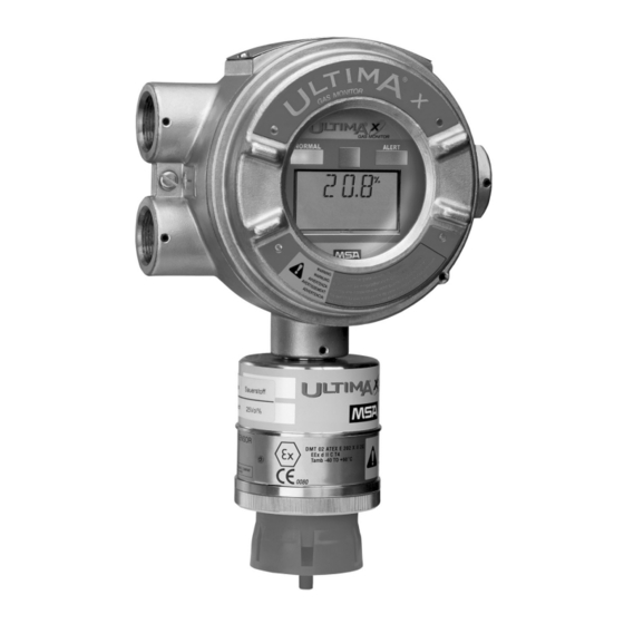
Description Overview ® The ULTIMA X Series instruments are housed in a flameproof enclosure and are calibrated at the factory ready for installation. The instrument components vary somewhat depending on the particular model. All models are provided with ¾" NPT or M25 x 1.5 cable entries. The following instrument types are available: ULTIMA XE Gas monitor with electronic display in a 316 stainless steel flameproof enclosure... - Page 26 Description All models in the ULTIMA® X Series can be equipped with remote sensors [ Fig. 3]. Fig. 1 ULTIMA – Gas monitor [ULTIMA XE shown here] Enclosure with viewing window Sensor electronics with optional LEDs and display Display Flameproof enclosure Sensor housing Sensor module SensorGard...
- Page 27 Description Fig. 2 ULTIMA – XIR Gas monitor Fig. 3 ULTIMA – Remote sensor module reactive gas ® ULTIMA X Series...
- Page 28 Description Fig. 4 ULTIMA – Remote sensor module non reactive gas Fig. 5 ULTIMA XA ® ULTIMA X Series...
-
Page 29: Installation
Installation Installation ® The ULTIMA X Series of Gas Monitors should be installed where gas leaks are expected. The installation is carried out depending on the gas density either in the upper area of the room under the ceiling or lower down close to the ground. The display on the front of the instrument must always be clearly visible, the view must not be obstructed. -
Page 30: Installation With Ultima® X Series Mounting Kit
Installation Installation with ULTIMA® X Series Mounting Kit ® Instruments from the ULTIMA X Series are installed at the place of installation on a mounting plate. Fig. 6 Mounting plate for ULTIMA XE and XIR Wall mounting fixing holes Instrument fixing holes Use M6 x 20 mm screws and suitable plugs for attaching the mounting plate to the wall. -
Page 31: Installing The Ultima Xa Gas Monitor
Installation During the assembly, the ULTIMA XE Gas Monitor enclosure can be ro- tated 360°, to ensure easy access to any of the four cable entries. For correct positioning of the display, the electronics assembly can be in- stalled in any of the four self-aligning positions. Installing the ULTIMA XA Gas Monitor (1) Remove lid and drill enclosure for power, signal and optional relay cable entry. - Page 32 Installation Instructions for electrical connection Twisted cable pair of a quality suitable for measuring instruments is recom- mended. Use shielded cable if there are any electromagnetic or other sources of interference [such as motors, welding appliances, heating appliances, etc.]. Always observe maximum cable lengths and cross-section [ Chapter 9.14 and 9.15].
- Page 33 Installation ALARM RELAY CONNECTIONS TROUBLE RELAY CONNECTOR HART PORT CONNECTOR PUSH BUTTON CONNECTOR 'J8' POWER CONNECTOR SENSOR CONNECTOR Fig. 7 Connections on the instrument board This shows all possible ULTIMA XE connections, three wire with 4-20 mA output and HART Protocol. If using the HART signal terminate the 4-20 mA line with 230 to 500 Ohms ®...
- Page 34 Installation Connecting the Cable in a Typical Gas Monitor from the ULTIMA® X Series The following procedure applies for 2-wire 4-20 mA Gas Monitors with control circuit and 3-wire Gas Monitors with separate power supply. ® Refer to ULTIMA X Series addendum "Gas Monitors with X3 Technol- ®...
-
Page 35: Ultima® X Series Remote Sensor Module Installation
Installation (6) Connect sensor module cable to J1 plug. (7) If necessary, connect cable for optional relay and/or the RESET button [ Chapter 12]. (8) Insert instrument electronics assembly into enclosure. (9) Screw cover onto enclosure. ULTIMA® X Series Remote Sensor Module Installation Attention! ®... - Page 36 Installation ® (5) For ULTIMA X Series [XE or XIR] instruments, feed the cable from the Gas Monitor through the wire entry provided in the remote housing and connect to the terminal strip. (6) Attach remote sensor module cover. Incoming power and signal cable shield should be connected to earth ground at the power source.
-
Page 37: Operation
Operation Operation Hand-held Controller and Calibrator The intrinsically safe ULTIMA/ULTIMA X Controller and Calibrator can be used to ® calibrate and change or view the configuration of ULTIMA X Series Gas Monitors. ULTIMA/ULTIMA X Calibrator A simple to use three button device with a non-invasive ®... -
Page 38: Hart Compatible Communications Interface
Operation HART Compatible Communications Interface The hand-held HART Communicator, such as the Emerson 375 Field Communica- tor, must be HART revision 7 compliant and can be obtained from a HART-autho- rised supplier. See chapter 13 for command definitions. Commissioning ® ULTIMA X Series instruments are calibrated at the factory and are immediately ready for use. -
Page 39: Calibration
Calibration In this case, the ULTIMA X Series Gas Monitor switches to one of the following operating modes: ® +LOC % LEL: The ULTIMA X Series Gas Monitor has been exposed to a high gas concentration [above the LEL], and there is a possibility that the over-range condition may still exist. -
Page 40: Calibration Basics
Calibration Calibration Basics ® ULTIMA X Series Gas Monitors are calibrated at the factory. Nevertheless, it is recommended to recalibrate the instrument after installation. The frequency of ca- libration depends on the duration of use and the chemical exposure of the sensor. New sensors must be calibrated frequently until it is clear from the calibration data that they have stabilised. - Page 41 Calibration For pump application the flow rate must be within 0.5 and 5 l/min. At the gas outlet a tube of at least 30 cm shall be used. Non-combustible Chemical Substances that cause Reduced Sensitivity of the Catalytic Sensor Catalytic sensors for combustible gases in areas where non-combustible chemical substances can escape must be calibrated after such an exposure.
- Page 42 The Ultima X Series Gas Monitor is factory-shipped with a preset span gas value - Factory-set Span Values. This span gas value can be changed using the MSA Ultima Controller or a HART controller; otherwise, the span gas must correspond to the preset concentra- tion.
- Page 43 Calibration Factory-set Span Values SPAN Gas Preset Gas Type Range Values Carbon Monoxide 0-100 ppm; 60 ppm 0-500 ppm 300 ppm 0-1000 ppm 400 ppm Sulfur Dioxide 0-25 ppm 10 ppm 0-100 ppm 10 ppm Hydrogen Sulfide 0-10 ppm 5 ppm 0-50 ppm 40 ppm 0-100 ppm...
-
Page 44: Initial Calibration
Calibration SPAN Gas Preset Gas Type Range Values Bromine 0-5 ppm 2.5 ppm Ammonia 0-100 ppm 25 ppm 0-1000 ppm 300 ppm Hydrogen 0-1000 ppm 500 ppm Ethylene Dioxide 0-10 ppm 4.0 ppm Carbon Dioxide IR 0-5000 ppm 3300 ppm 0-2% 1.5% 0-5%... - Page 45 Calibration FAULT function to work properly. Additionally, INITIAL Calibration should only be used when a regular calibration will not clear a fault condition due to use of incorrect cal gas or other similar situation. Initial calibration is accomplished by: Push-Button - using the optional push-button as outlined in [ chapter 12.6 "Calibration with RESET button"] HART Communicator - ...
-
Page 46: Regular Calibration
Calibration Regular Calibration A regular calibration includes "zero" and "span" as described in the following pro- cedures. Zeroing Using the Zero Cap This method is only suitable when the atmosphere contains no traces of the gas to detect. Otherwise, use zero gas. (1) Place the zero cap of the corresponding calibration kit over the SensorGard and wait two minutes. - Page 47 Calibration The display shows: A countdown from 30 to 0 seconds the APPLY ZERO GAS indicators [ Fig. 10]. Fig. 10 Prompt for supplying zeroing gas (8) After the 30 second countdown: CAL and a numeric value will be displayed alternately on the display, which is the actual reading of the gas concentration the sensor is detecting.
- Page 48 Calibration The ULTIMA X Series Monitor allows automatic zero adjustment only within a pre- defined range. Outside this range, no corrections can be made, e.g. when an empty or wrong gas cylinder is connected or the gas flow did not start within the 30 seconds countdown period.
- Page 49 Calibration (5) When using cal-kit 41, use the calibration cap which has a hole for the tube. push the tube through the hole in the bottom of the cap, connect the tube end over the sensor inlet and ...
- Page 50 Calibration If CAL FAULT is displayed, this indicates: The calibration of the ULTIMA® X Series Gas Monitor has failed. The ULTIMA X Series Gas Monitor is operating with the calibration parameters which were determined before beginning the calibration [ chapter 11.3 "Instructions for troubleshooting"].
-
Page 51: Maintenance
® ULTIMA X Series Gas Monitor, beyond the scope of these instructions or by anyone other than authorised MSA service personnel may serious- ly impair instrument performance. ULTIMA XIR Cleaning Procedure Before cleaning the ULTIMA XIR sensor window disable the alarm re- lays using the ULTIMA/ULTIMA X Controller. - Page 52 Maintenance Attention! Do not place foreign objects in the sensor's analytical region [except per the "ULTIMA XIR Cleaning Procedure" as described above]; otherwise, the infrared beam can be partially blocked, causing the sensor to gene- rate false readings. All objects must be removed from the sensor's ana- lytical region for it to function properly.
-
Page 53: Replacing The Ultima Xe/Xa Sensor
Maintenance The unit remains in the Cleaning Mode for a minimum of two minutes. If ac- tive cleaning is still in progress at the end of this period, the sensor detects the motion of this object in its light path and automatically extends the Clean- ing Mode for 15 seconds. - Page 54 Maintenance A leaking sensor must not be installed in the sensor housing. Dispose of leaking sensors in accordance with local regulations. Replacement sensors can be ordered from MSA [Order details chap- ter 8.2]. Attention! For ULTIMA XE/XA Gas Monitors, first unscrew the sensor by rotating it at least three full turns [maximum four turns from its tightly closed posi- tion], wait for 10 seconds and unscrew the sensor completely.
-
Page 55: Technical Data
Technical Data Alarm setpoints and relay functions [energised/de-energised] will not change when changing a sensor from its current type to the same gas type. Alarm setpoints and the upscale/downscale relay function will change to the new sensor’ settings when changing a sensor module from its cur- rent type to a different gas type. -
Page 56: Performance Specifications
Technical Data Performance Specifications Gas types Combustible gases, oxygen and toxic gases Tempera- Toxic gases and Operating range 0 °C to 40 °C ture range oxygen Extended range -20 °C to +50 °C Operating range NH 0 °C to 30 °C Extended range NH -10 °C to 40 °C ;... - Page 57 Technical Data Gas types Combustible gases, oxygen and toxic gases ULTIMA XE ULTIMA XIR combustible Response time with 15 sec 35 sec 15 sec 35 sec Methane sensor gard/ 25 sec 55 sec 15 sec ...
-
Page 58: Measuring Accuracy
Technical Data Gas types Combustible gases, oxygen and toxic gases Power input mA versions Toxic gases and oxygen 19 - 30 max. (for instru- V DC 24 mA at ments with 24 V DC internal re- Combustible gases, 19 - 30 max. -
Page 59: Ultima Xe - Atex Performance Approval
Technical Data Linearity Repeatability 10 % FS 10 % FS Arsine 10 % FS or 2 ppm 10 % FS Germanium 10 % FS or 2 ppm 1 % FS or 2 ppm Silane 10 % FS or 2 ppm 1 % FS or 2 ppm Diborane 10 % FS or 2 ppm... - Page 60 Technical Data ULTIMA XE - Relative Response Factors Relative response factors of tested gases for 0.89 Vol% Propane calibration gas. 100 % LEL in Relative re- Response Response Measuring gas Vol% sponse factor time [t50] time [t90] 19 s ...
-
Page 61: Ultima Xir - Atex Performance Approval
Technical Data ULTIMA XIR – ATEX Performance Approval When monitoring flammable gas in safety related applications the ULTIMA XIR must be calibrated with a known concentration of the gas being monitored. The lower explosive limits [LEL] of the gases and vapours in the following tables were taken from EN 60079-29-1:2007. - Page 62 Technical Data ULTIMA XIR - Relative Response Factors for Propane Calibration Gas Reference Gas Relative 100 % LEL in Linearisation Measuring gas Concentration response Vol% curve [Propane] factor Acetone 2.5 Vol% (8) Ethylene 0.25 Vol% 3.31 Allyl alcohol 2.5 Vol% (2) Propane 0.25 Vol% 3.31...
- Page 63 Technical Data Reference Gas Relative 100 % LEL in Linearisation Measuring gas Concentration response Vol% curve [Propane] factor Toluene 1.1 Vol% (8) Ethylene 0.25 Vol% 3.75 Xylene 0.96 Vol% (2) Propane 0.41 Vol% 2.56 Response time with measuring gas when using the ULTIMA XIR Flow Cap [flow rate 1 l/min.]: 50 = 10 s, t = 30 s.
-
Page 64: Ordering Information
Ordering Information 100 % LEL in Response to 50 % LEL of the Measuring gas Vol% measuring gas Ethanol 3.1 Vol% 48 % LEL Ethylene 2.3 Vol% 8 % LEL Ethyl Acetate 2.2 Vol% 33 % LEL Ethylene Oxide 2.6 Vol% 27 % LEL n-Hexane 1.0 Vol%... - Page 65 Ordering Information Description Part No. Accessories ULTIMA XE Calibration Cap 10020030 ULTIMA XE SensorGard 10028904 ULTIMA XIR SensorGard 10041265 ULTIMA XIR Calibration Cap 10041533 ULTIMA XE Flow Cap 10041866 ULTIMA XIR Flow Cap 10042600 ULTIMA Controller 10044459 ULTIMA Calibrator 10044470 Cable Gland M25 EEx d 10045619 Cable Gland M20 EEx d...
-
Page 66: Replacement Parts
Ordering Information Replacement Parts Description Part No. Carbon Monoxide, 0 – 100 ppm 10044471 Carbon Monoxide, 0 – 500 ppm 10044472 Oxygen, 0 – 10 % - compensated 10044473 Oxygen, 0 – 25 % - compensated 10044474 Hydrogen Sulfide, 0 – 10 ppm 10044475 Hydrogen Sulfide, 0 –... -
Page 67: Appendix: Electrical Installation
Appendix: Electrical Installation Appendix: Electrical Installation The cabling and electrical installation must be carried out based on the instrument types used. Electrical installation details are given in appropriate drawings. Installation Outline Drawing [CE] - ULTIMA XE 160.3 99.3 10-32 mounting screw holes (2 places) ¾″... -
Page 68: Installation Outline Drawing [Ce] - Ultima Xe With Xir Sensor
Appendix: Electrical Installation Installation Outline Drawing [CE] - ULTIMA XE with XIR Sensor 10-32 Mounting screw holes (2 places) Notes: Instrument weight: 4.8 kg Dimensions shown in millimetres. Install XIR sensor horizontal as shown. Cable gland threads are M25 x 1.5 mm OR 3/4” NPT x 14 Instrument housing: 316 St.St. -
Page 69: Installation Outline Drawing [Ce] - Ultima Xa
Appendix: Electrical Installation Installation Outline Drawing [CE] - ULTIMA XA ® ULTIMA X Series... -
Page 70: Installation - Mounting Bracket
Appendix: Electrical Installation Installation - Mounting Bracket Optional ULTIMA XE and XA Mounting Bracket ® ULTIMA X Series... -
Page 71: Remote Non-Reactive Sensor And Mounting Bracket
Appendix: Electrical Installation Remote non-reactive sensor and mounting bracket Check Tag for area classification Check Tag for area classification (Mount unit with sensor inlet facing down) ® ULTIMA X Series... -
Page 72: Hart Module
Appendix: Electrical Installation HART module 109.45 [4.309] ® ULTIMA X Series... -
Page 73: Ultima Xir Remote Sensor
Appendix: Electrical Installation ULTIMA XIR Remote Sensor Mount unit with sensor inlet horizontal Check tag for area classification ® ULTIMA X Series... -
Page 74: Installation Outline Drawing [Ce] - Ultima Xe Wiring Connections
Appendix: Electrical Installation Installation Outline Drawing [CE] - ULTIMA XE Wiring Connections NORMALLY CLOSED DE-ENERGIZED COMMON ALARM 2 CONNECTIONS NORMALLY CLOSED ENERGIZED NORMALLY CLOSED DE-ENERGIZED NORMALLY CLOSED ENERGIZED COMMON COMMON NORMALLY CLOSED NORMALLY CLOSED ENERGIZED DE-ENERGIZED ALARM 3 CONNECTIONS ALARM 1 CONNECTIONS TROUBLE RELAY CONNECTIONS NORMALLY OPEN ENERGIZED COMMON... -
Page 75: Hart Module Connections
-GROUND- SIGNAL (S) SIGNAL PWR (+) +POWER+ SHIELD SHIELD SHIELD 9.10 Connection to MSA Controllers Maximum cable lengths in metres for cable with 1.5 mm 9010/20 ULTIMA X Type SUPREMA E292 VP Gasgard XL V-Factor [12 VA] OX-TOX [2 wire]... -
Page 76: Connection Drawings - Suprema
Appendix: Electrical Installation 9.11 Connection Drawings - SUPREMA -X 1 4 - 2 0 mA + 2 4 VD C P o w e r G N D Fig. 15 Connection drawing - ULTIMA X [3-wire] to SUPREMA SUPREMA ULTIMA X -X 1 4 - 2 0 mA + 2 4 VD C... -
Page 77: Connection Drawings - 9010/9020
Appendix: Electrical Installation 9.12 Connection Drawings - 9010/9020 G N D + 2 4 VD C P o w e r 4 - 2 0 mA Fig. 17 Connection drawing - ULTIMA X [3-wire] to 9010/20 LCD Terminal block 9010/9020 ULTIMA X + 2 4 VD C P o w e r... -
Page 78: Connection Drawings - Gasgard
Appendix: Electrical Installation 9.13 Connection Drawings - Gasgard Fig. 19 Connection drawing - ULTIMA X [3-wire] to Gasgard XL Channel card - Gasgard XL ULTIMA X Fig. 20 Connection drawing - ULTIMA X [2-wire] to Gasgard XL Channel card - Gasgard XL ULTIMA X ®... -
Page 79: Cable Lengths And Cross-Section - Gas Monitors
Appendix: Electrical Installation 9.14 Cable Lengths and Cross-section - Gas Monitors Toxic Gases and Oxygen Sensors with 4-20 mA Signal Output [2- wire Sensor] Cross-section Max. length at 24 V DC Max. load resistance 1.0 mm 2134 m 500 Ohm Catalytic Combustible Gas Sensor with 4-20 mA Signal Output [3- wire Sensor] Power supply... -
Page 80: Cable Lengths And Cross-Section - Remote Sensor Module *)
Appendix: Instrument Specifications 9.15 Cable lengths and Cross-section - Remote Sensor Module *) Minimum cross-section Maximum length Toxic gases and oxygen 1.00 mm 30 m Combustible gases, 1.00 mm 15 m catalytic 1.50 mm 30 m Combustible gases, IR 1.50 mm 15 m 2.50 mm 30 m... - Page 81 Appendix: Instrument Specifications Operating 4 – 20 mA Fault relay mode GREEN RED Sensor 3.0 mA if SWAP delay De-energised if SWAP missing / time-out expired delay timeout expired, Countdown SWAP delay disabled SWAP delay disabled or FAULT or FAULT Last gas value, if Energised, if SWAP delay SWAP delay enabled...
-
Page 82: Sensor Response To Interferants
Appendix: Instrument Specifications 10.2 Sensor Response to Interferants Concen- Interferant tration filtered filtered [ppm] Acetone 1000 No Data 0 Acetylene 12000 No Data No Data Ammonia No Data 0 Arsine No Data Benzene No Data No Data Bromine No Data Carbon 5000 Dioxide... - Page 83 Appendix: Instrument Specifications Concen- Interferant tration filtered filtered [ppm] Hydrogen -0.1 Sulfide Mercaptan -0.1 No Data [Methyl] Methane 5000 Nitric Oxide No Data Nitrogen Dioxide Phosphine No Data 0 No Data No Data Silane No Data Sulfur No Data Dioxide Tichloro- 1000 No Data...
- Page 84 Appendix: Instrument Specifications Concen- Interferant tration [ppm] Carbon Disulfide Data Carbon Monoxide Data Chlorine -0.2 Data Data Data Diborane Data Data Ethylene -0.3 Data Data Ethyl Alcohol Data Data Data Data Data Ethyle Oxide Data Data Data Data Data Data Ether Data Data...
- Page 85 Appendix: Instrument Specifications Concen- Interferant tration [ppm] Data Data Data Data Data Data Mercaptan [Methyl] Data Data Data Data Data Methane 5000 Data Data Data Data Nitric Oxide Data Data Data Nitrogen Dioxide Data Data Data Data Phosphine Data Data Silane Data Data...
- Page 86 Appendix: Instrument Specifications Concen- Interferant tration [ppm] Carbon 5000 Dioxide Data Data Data Carbon Disulfide Data Data Data Carbon Monoxide Data Chlorine Data Data Diborane Data Data Data Ethylene Data Ethyl Alcohol 100 Data Data Data Data Ethyle Oxide 10 Data Data Data...
- Page 87 Appendix: Instrument Specifications Concen- Interferant tration [ppm] Hydrogen -0.2 Sulfide Data Data Data Data Data Data Mercaptan -0.2 [Methyl] Data Data Data Data Data Methane 5000 Data Data Data Data Data Nitric Oxide Data Data Data Nitrogen Dioxide Data Data Data Phosphine Silane...
-
Page 88: Appendix: Instrument Messages
Appendix: Instrument Messages Appendix: Instrument Messages 11.1 Messages during Instrument Operation Messages Meaning MM/DD/YY Date format Software version TIME Time DATE Date MINIMUM value of interval MAXIMUM value of interval Average gas concentration of interval Instrument address Calibration cycle ends Error code Hour display [one or two character] OVER... -
Page 89: Instructions For Troubleshooting
Appendix: Instrument Messages Messages Meaning TBLE Instrument gas table selection [if applicable] ALERT OP ON Instrument output will follow ALERT mode ALERT OP OFF Instrument will not follow ALERT mode SWAP DELAY ON 60 second delay after sensor missing before fault SWAP DELAY OFF Fault occurs at sensor missing condition 11.3 Instructions for Troubleshooting Message... - Page 90 Appendix: Instrument Messages Message Meaning Remedy RELAY FAULT An error has occurred in the Disconnect instrument internal relays from power supply and connect again replace printed board. SNSR POWER Power supply of sensor mod- Correct wiring fault re- FAULT ule outside permissible range place printed circuit board or sensor module.
- Page 91 Appendix: Instrument Messages Message Meaning Remedy ZERO CAL FAULT / Instrument did not calibrate Repeat calibration SPAN CAL FAULT successfully Check if the correct cali- bration gas was used . Check flow system for blockage SENSOR WARN- Sensor life has almost ex- Prepare to replace sen- pired sor.
-
Page 92: Appendix: Optional Internal Relays And Reset Button
Appendix: Optional Internal Relays and RESET Button Appendix: Optional Internal Relays and RESET Button 12.1 General The internal relays are designed to enable ULTIMA® X Series Gas Monitors to con- trol other equipment. The four optional relays are located under the display module and provide the following functions: three alarm relays and one fault relay. - Page 93 Appendix: Optional Internal Relays and RESET Button ® Permissible Cable Length for the ULTIMA X Series with Internal Relays [4-20 mA models] The permissible cable length varies for models with or without internal relays. Supply Wire cross- Max. cable Max. load resist- Sensor type voltage section...
-
Page 94: Alarm Relays
Appendix: Optional Internal Relays and RESET Button 12.3 Alarm Relays [ Fig. 7 in chapter 3.4] ® There are three alarm relays and one fault relay in the ULTIMA X Series Gas Monitors. The three alarm relays will be activated if the sensor detects a gas concentration that lies outside the limit values. -
Page 95: Fault Relay [Trouble]
Appendix: Optional Internal Relays and RESET Button 12.4 Fault Relay [Trouble] [ Fig. 7 in chapter 3.4] It is a normally-energised, single-pole, double throw [SPDT] relay. During normal operation, the normally closed [NC] contacts are closed. When a fault is detected or the power is disconnected the relay contacts will change as follows: the normally closed contacts [NC] will open the normally open contacts [NO] will close... -
Page 96: Calibration With Reset Button
These effects may damage the instrument and make it inoperative. One way to reduce these effects is to install a “Quencharc”, available from MSA as part number 630413, across the load being switched. - Page 97 Appendix: Optional Internal Relays and RESET Button Attention! Before connecting the cable to ULTIMA® X Series Gas Monitors, dis- connect or isolate the monitor power source otherwise there is danger of electric shock. To connect the relay, the ULTIMA® X Series Gas Monitor must be opened. Pro- ceed as described below: ®...
-
Page 98: Appendix: Hart Specific Information
Appendix: HART Specific Information Appendix: HART Specific Information 13.1 HART Field Device Specification The ULTIMA X Series Gas Monitor is available with an optional HART [Highway Addressable Remote Transducer] output communications protocol. With this op- tion, the ULTIMA X Series Gas Monitor complies with HART Protocol Revision 7 and uses the 16-bit manufacturer and device codes. - Page 99 Appendix: HART Specific Information Host Interface Analogue Output The three-wire 4-20 mA current loop is connected on terminals marked 8-30 VDC [1], 4-20 mA OUT[2], and GND [3-wire] [3]. The two-wire 4-20 mA cur- rent loop is connected on the 8-30 VDC[1] and 4-20 mA OUT[2] terminals. Refer to the installation outline drawings for details.
- Page 100 Appendix: HART Specific Information Device Variables Exposed by the ULTIMA Monitor Variable Description Variable Description Gas Type Sensor gas type Last Cal Date Date sensor was description last calibrated Alarm Setpoints Gas value at which Auto Zero comp Amount of compen- an alarm status bit is sated below zero drift...
- Page 101 Appendix: HART Specific Information Status Information Device Status Bit 4 ["More Status Available"] is set when any failure is detected. Command #48 gives further details. Extended Device Status The ULTIMA Monitor can predict when certain maintenance will be required. This bit is set if a sensor fault or maintenance warning is detected.
- Page 102 Appendix: HART Specific Information Span Fault Info Cal OK Info End of Life Warning Warning Sensor Swap Delay Info Change Sensor Fault Error Sensor Power Fault Error Internal Comm Fault Error Cal Sig Enable Info Alert Option Enable Info Relay Fault Error Alarm 1 Set Warning...
-
Page 103: Universal Commands
Appendix: HART Specific Information 13.2 Universal Commands All Universal commands have been implemented in the ULTIMA Gas Monitor. The ULTIMA Gas Monitor returns a 7 in the Universal rev to indicate the device is using the expanded 16-bit manufacturer and device codes. 13.3 Common-Practice Commands The following Common Practice commands have been implemented in the ULTIMA device:... - Page 104 Appendix: HART Specific Information Device-Specific Commands The following device-specific commands are implemented in the ULTIMA Monitor: Command # Description Read Sensor Gas Type Read Device RTC Read Alarm Setpoints Read Alarm Control Actions Read Min/Max/Average Values Read Last Cal Date Read Gas Table Read Input Voltage Read Auto Zero Comp...
- Page 105 Appendix: HART Specific Information Command # Description Write Relay Normal State Command #129: Read Sensor Gas Type Reads the Gas Type of the sensor currently connected to the ULTIMA Gas Monitor. Request Data Bytes None. Response Data Bytes Byte Format Description ASCII Sensor gas type description...
- Page 106 Appendix: HART Specific Information Command #132: Read Alarm Control Actions Reads the ULTIMA X Alarm Control Actions. Request Data Bytes None. Response Data Bytes Byte Format Description Bit Enum Alarm 1 Control Actions [ Table 13.5] Bit Enum Alarm 2 Control Actions [ Table 13.5] Bit Enum Alarm 3 Control Actions [...
- Page 107 Appendix: HART Specific Information Command #134: Read Last Cal Date Returns the ULTIMA last calibration date of the currently connected sensor. Request Data Bytes None. Response Data Bytes Byte Format Description Unsigned Last sensor calibration date Command #135: Read Gas Table This command returns the ULTIMA sensor Gas Table currently in use.
- Page 108 Appendix: HART Specific Information Command #137: Read Auto Zero Comp Value Returns the ULTIMA Automatic Zero Compensation value. This value is accumu- lated by the device when the sensor reading attempts to drift below zero. This value is used to compensate the actual Zero calibration. The device will attempt to com- pensate up to 10 counts [display units] before setting the under-range bit.
- Page 109 Appendix: HART Specific Information Command #141: Read Cal Signal Status This command returns the ULTIMA X Cal Signal status. This is a single byte con- taining a 0 if disabled or 1 if enabled. If enabled, the output will be set to 3.75 mA during calibration [21 mA for oxygen].
- Page 110 Appendix: HART Specific Information Command #144: Read Relay Normal State This command returns the ULTIMA X to the Normal relay state. This is a single byte containing a bit map of the three alarm relays’ non alarm states. Not all gas sensors have on-board relays.
- Page 111 Appendix: HART Specific Information Command #173: Write RTC Writes the ULTIMA Real Time Clock hours and minutes values.The real time clock is used to compute the minimum, maximum and average values and to date stamp the last sensor calibration date. Request Data Bytes Byte Format...
- Page 112 Appendix: HART Specific Information Command #174: Write Alarm Setpoints Writes the ULTIMA Alarm Setpoint values. The ULTIMA Gas Monitor uses alarm setpoint values to set alarm status bits in the device. The alarms can be enabled or disabled, set to increasing or decreasing and can be set to latching. The alarm ad- justment range is greater than zero and less than full-scale [see "Command 175: Write Alarm Setpoint Control Actions"].
- Page 113 Appendix: HART Specific Information Command #175: Write Alarm Setpoint Control Actions Writes the ULTIMA X Alarm Setpoint Control Actions. The ULTIMA X Gas Monitor uses alarm setpoint Control Actions to enabled or disabled, set to increasing or de- creasing and to set the alarm to latching or non latching. Request Data Bytes Byte Format...
- Page 114 Appendix: HART Specific Information Command #176: Write Average Interval Writes the ULTIMA Average Interval. This interval is in hours and is used by the de- vice to determine the collection interval for Minimum, Maximum and Average val- ues. The Average collection interval can be for 1, 8 or 24 hours. Request Data Bytes Byte Format...
- Page 115 Appendix: HART Specific Information Command #177: Write Upper Trim Point Writes the ULTIMA X Upper Trim or Span point value. The ULTIMA Gas Monitor uses the Upper trim point value to perform Span calibration. When a Span calibra- tion is performed, the device automatically sets the highest reading obtained to this Span value.
- Page 116 Appendix: HART Specific Information Command #178: Write Gas Table Writes the ULTIMA X Gas Table selection. The ULTIMA Gas Monitor uses the Gas Table value to select a reference table of linearisation values for certain sensors. Request Data Bytes Byte Format Description Unsigned...
- Page 117 Appendix: HART Specific Information Command #179: Write Sensor Data Sheet Reset Control Writes a data sheet reset command to ULTIMA X Gas Monitor. This command causes the ULTIMA Monitor to reset the current sensor data sheet to factory default settings. This command will set certain device warning status bits and require the user to re-calibrate the sensor.
- Page 118 Appendix: HART Specific Information Command #180: Write Sensor Swap Delay Enable This command writes command number to the ULTIMA X Gas Monitor to enable or disable the two-minute swap delay feature. This device feature enables a two- minute hold-off of the sensor missing fault, allowing the user to “Swap” or change sensor modules without having the 4-20 mA set to the fault condition.
- Page 119 Appendix: HART Specific Information Command #181: Write Cal Signal Enable This command writes command number to the ULTIMA X Gas Monitor to enable or disable the Cal signal output. Without the Cal Signal enabled, the 4-20 mA output will follow the gas reading during calibration. With the Cal Signal enabled, the 4-20 mA output will be set to 3.75 mA during calibration and be held there for one minute after calibration has ended to allow the sensor to re-stabilise.
- Page 120 Appendix: HART Specific Information Command #182: Write Calibration Mode This command writes a calibration mode number to the ULTIMA Gas Monitor. The mode commands initiate a calibration sequence in the device. Device status byte 2 can be monitored to determine the progress of the calibration. Request Data Bytes Byte Format...
- Page 121 Appendix: HART Specific Information Command #183: Write Calibration Abort This command writes a calibration Abort command to the ULTIMA Gas Monitor. The calibration abort command instructs the device to suspend the calibration se- quence initiated by the calibration mode command. Valid number for this command is 1.
- Page 122 Appendix: HART Specific Information Command #184: Write Calibration Step This command writes a calibration Step Command to the ULTIMA Gas Monitor. The Step command instructs the device to advance to the next step during a manual ca- libration sequence. Device status byte 2 can be monitored to determine the progress of the calibration.
- Page 123 Appendix: HART Specific Information Command #185: Write Alarm Acknowledge This command writes an Alarm Acknowledge command to the ULTIMA X Gas Monitor. The alarm acknowledge command instructs the device to clear any latched alarms in the device, provided the setpoint level for the alarm has receded. Valid command number is on 1.
- Page 124 Appendix: HART Specific Information Command #186: Write Protect Mode This command sends a single, unsigned byte to the device. Sending a 1 puts the device in write protect mode. In write protect mode, all writes and commands are ignored except a command to disable the write protect. Only reads to the device can be made.
- Page 125 Appendix: HART Specific Information Command #187: Write Alert Option This command disables or enables the Alert Option on the ULTIMA X unit. This is a single byte containing a 0 if disabled or 1 if enabled. If enabled, the Alert Option will cause the 4-20 mA to be set to 3.75 mA during calibration of an Oxygen sensor [if the Cal Signal Option is also enabled].
- Page 126 Appendix: HART Specific Information Command-Specific Response Codes Code Class Description Success No Command-Specific Errors Undefined Error Parameter too large Undefined Error Too few data bytes Undefined Error In write protect mode 8-15 Undefined Error Access Restricted 17-31 Undefined Error Busy 33-127 Undefined ®...
- Page 127 Appendix: HART Specific Information Command #188: Write Relay Normal State This command sets the ULTIMA X Normal relay state. This is a single byte contai- ning a bit map of the three alarm relays’ non alarm states. Not all gas sensors have on-board relays.
-
Page 128: Gas Type Descriptions
Appendix: HART Specific Information 13.4 Gas Type Descriptions Gas Type Description Carbon Monoxide Oxygen COMB Combustible-pellistor Infrared Combustible Hydrogen Sulfide Chlorine Chlorine Dioxide Ammonia 13.5 Alarm Control Actions Bit 0 Alarm Enable 1 = enabled, 0 = disabled Bit 1 Alarm Direction 1 = increasing, 0 = decreasing Bit 2... -
Page 129: Sensor Status Codes
Appendix: HART Specific Information 13.7 Sensor Status Codes Code Description 0x01 Flash Fault 0x05 Ram Fault 0x07 Pellement Fault 0x0A Data Sheet Fault 0x1E Power Fault 0x1F IR Factory Mode 0x20 IR Lamp Fault 0x28 EEPROM R/W Fault 0x2D EEPROM Checksum Fault 0x2F Sensor Missing Fault 0x3A... -
Page 130: Gas Table Values
Appendix: HART Specific Information 13.8 Gas Table Values Table Description Methane Propane Ethane n-Butane n-Pentane n-Hexane Cyclopentane Ethylene Acetylene 5000 PPM CO 5% CO 2% CO Custom Unused ® ULTIMA X Series... -
Page 131: Performance
Appendix: HART Specific Information 13.9 Performance Typical sampling rates are shown in the following table. Sampling Rates Gas Samples 4 per second PV digital value calculation 5 per second Analogue output update 5 per second Power-Up On power-up, the transmitter goes through a self-test procedure, and a sensor warm up and initialisation period which takes approximately 30 seconds. - Page 132 Appendix: HART Specific Information Self-Test The self-test procedure is executed at power-up or following Command 42 ["Device Reset"]. Some self-test procedures are continuously run in a background mode. The self-test includes: Microprocessor Program ROM Configuration storage EEPROM Sensor communications Data sheet integrity Internal communications.
-
Page 133: Capability Checklist
Damping Damping is internally-fixed, affecting only the PV and the loop current signal. There is no user-settable damping control. 13.10 Capability Checklist Manufacturer, model and revision MSA, ULTIMA, rev. 2 Device type Transmitter HART revision Device Description available? Number and type of sensors... -
Page 134: Default Configuration
Appendix: HART Specific Information 13.11 Default Configuration Parameter Default Value Lower Range Value Upper Range Value Sensor dependent PV Units Sensor dependent Sensor type various Number of wires Damping time constant Fault-indication jumper Sensor dependent Write-protect mode write enabled Number of response preambles Alarms Enabled 13.12 Calibration Using a HART®... - Page 135 Appendix: HART Specific Information First warning screen Once the sensor calibration feature is selected, a warning message displays to in- dicate that the 4-20 mA output should be disabled from any automatic control loop to prevent false action during calibration. The user must acknowledge this screen to continue.
-
Page 136: Standard Calibration Procedures
Appendix: HART Specific Information Sensor Zero countdown screen Once the information screens are displayed, the device should start sending back a status byte to indicate calibration progress. The first status message should be the 30-second device countdown message. This message prompts user to start ap- plying Zero gas if necessary. - Page 137 Appendix: HART Specific Information to prevent false action during calibration. The user must acknowledge this screen to continue. Fig. 26 for a view of this warning screen. Optionally, the user may abort the process at this screen. Second warning screen After acknowledgement of the control loop message, a second warning message displays, informing the user that sensor calibration will be changed.
- Page 138 Appendix: HART Specific Information Selection confirmation screen After the initiating screen displays for five seconds, a second information screen displays. This screen displays for five seconds and provides the user confirmation of the current calibration selection. No action is required at this screen, but the user may press the ABORT button to stop the process.
- Page 139 Appendix: HART Specific Information Adjusting Span screen After the 30-second Span initialisation, a Span adjustment screen displays and con- tinually updates with the gas [PV] reading, units and type information. Once the de- vice detects a stable reading, the data is stored automatically and the user is notified of the completion status.
-
Page 140: Initial Calibration Procedures
Appendix: HART Specific Information 13.14 Initial Calibration Procedures Initial Calibration Selection Menu Initial calibration is selected in a manner similar to the standard Zero/Span calibra- tion procedure and the steps are similar [except the function selection should be “Initial Cal”]. Initial calibration should be run when a new sensor is connected to the unit or when a standard Zero/Span procedure will not clear a fault condition [such as when the wrong Span gas is used]. - Page 141 Appendix: HART Specific Information Zero Cal Step Screen Fig. 21 Zero cal step screen Fig. 22 Zero cal step screen ® ULTIMA X Series...
- Page 142 Appendix: HART Specific Information Span Cal Step Screen Fig. 23 Span cal step screen Fig. 24 Span cal step screen ® ULTIMA X Series...
-
Page 143: Sample Calibration Display Screens
Appendix: HART Specific Information 13.16 Sample Calibration Display Screens HART DDL-based Calibration Display Screens Fig. 25 Select Sensor Calibration from the Sensor Trim Menu ® ULTIMA X Series... - Page 144 Appendix: HART Specific Information First Warning Screen Fig. 26 First warning screen Fig. 27 First warning screen ® ULTIMA X Series...
- Page 145 Appendix: HART Specific Information Second Warning Screen Fig. 28 Second warning screen Fig. 29 Second warning screen ® ULTIMA X Series...
- Page 146 Appendix: HART Specific Information Standard Calibration Function Select Screen Fig. 30 Standard calibration function select screen Fig. 31 Standard calibration function select screen ® ULTIMA X Series...
- Page 147 Appendix: HART Specific Information Calibration Initiated Screen Fig. 32 Calibration initiated screen Fig. 33 Calibration initiated screen ® ULTIMA X Series...
- Page 148 Appendix: HART Specific Information Selection Confirmation Screen Fig. 34 Selection confirmation screen Fig. 35 Selection confirmation screen ® ULTIMA X Series...
- Page 149 Appendix: HART Specific Information Sensor Zero Countdown Screen Fig. 36 Sensor zero countdown screen Fig. 37 Sensor zero countdown screen ® ULTIMA X Series...
- Page 150 Appendix: HART Specific Information Zero Adjustment Screen Fig. 38 Zero adjustment screen Fig. 39 Zero adjustment screen ® ULTIMA X Series...
- Page 151 Appendix: HART Specific Information Span Countdown Screen Fig. 40 Span countdown screen Fig. 41 Span countdown screen ® ULTIMA X Series...
- Page 152 Appendix: HART Specific Information Adjusting Span Screen Fig. 42 Adjusting span screen Fig. 43 Adjusting span screen ® ULTIMA X Series...
- Page 153 Appendix: HART Specific Information Calibration Completion Message Fig. 44 Calibration completion message Fig. 45 Calibration completion message ® ULTIMA X Series...
- Page 154 Appendix: HART Specific Information Calibration Gas Reminder Screen Fig. 46 Calibration gas reminder screen Fig. 47 Calibration gas reminder screen ® ULTIMA X Series...
- Page 155 Appendix: HART Specific Information Loop Control Reminder Message Fig. 48 Loop control reminder message Fig. 49 Loop control reminder message ® ULTIMA X Series...
-
Page 156: Troubleshooting
Appendix: HART Specific Information 13.17 Troubleshooting Fault Indications Span Fault This fault can occur if the sensor is in cal mode and the required SPAN gas is not applied to the sensor at the indicated time or within the timeout period. The 4-20 mA returns the measured gas value. - Page 157 Appendix: HART Specific Information Calibration Status Screen Fig. 50 Calibration status screen Fig. 51 Calibration status screen ® ULTIMA X Series...
- Page 158 Appendix: HART Specific Information Sensor Trim Point Screen Fig. 52 Sensor trim point screen ® ULTIMA X Series...
- Page 159 Appendix: HART Specific Information Additional Sensor Status Screen Fig. 53 Additional Sensor status screen Fig. 54 Additional Sensor status screen ® ULTIMA X Series...
- Page 160 Appendix: HART Specific Information Zero Fault The Zero Fault can be caused by a faulty sensor, calibration out of the Standard Zero/Span calibration range, sensor in change, sensor fault or attempting to zero the sensor with Span gas applied. The application of Zero gas should be checked and the sensor status [as defined in ...
- Page 161 Appendix: HART Specific Information Device Status Screen Fig. 55 Device status screen Fig. 56 Device status screen ® ULTIMA X Series...
- Page 162 Eastern Europe Central Europe Netherlands France Poland Germany MSA Nederland MSA GALLET MSA Safety Poland Sp. z o.o. MSA AUER GmbH Kernweg 20 Zone Industrielle Sud Ul. Wschodnia 5A Thiemannstrasse 1 1627 LH Hoorn 01400 Châtillon sur 05-090 Raszyn k/Warszawy...
Need help?
Do you have a question about the ULTIMA X-Series and is the answer not in the manual?
Questions and answers