MSA ULTIMA X5000 Operating Manual
Gas monitor
Hide thumbs
Also See for ULTIMA X5000:
- Quick start manual (3 pages) ,
- Safety manual (22 pages) ,
- Operating manual (95 pages)
Table of Contents
Advertisement
Advertisement
Table of Contents

Related Manuals for MSA ULTIMA X5000


Summary of Contents for MSA ULTIMA X5000
- Page 1 Operating Manual ULTIMA® X5000 Gas Monitor Order No.: 10177361/02 MSAsafety.com...
- Page 2 "Test Method" - appendixes to Pattern Approval Certificate of Measuring instrument, valid in the coun- tries of use. 1000 Cranberry Woods Drive Cranberry Township, PA 16066 Phone 1-800-MSA-2222 Fax 1-800-967-0398 For your local MSA contacts please go to our website www.MSAsafety.com © MSA 2018. All rights reserved...
-
Page 3: Table Of Contents
Contents Safety Regulations ..............Correct Use . - Page 4 Calibration ............... . Calibration Equipment .
-
Page 5: Safety Regulations
Safety Regulations Correct Use The ULTIMA X5000 Gas Monitor, hereafter also called device, is a gas monitor for measuring toxic and combustible gases as well as oxygen. Using sensors, the device tests the ambient air and triggers the alarm as soon as the gas exceeds a specific concentration level. -
Page 6: Product Warranty
Safety Code 6, obtainable from Health Canada's website www.hc-sc.gc.ca. Product Warranty ITEM WARRANTY PERIOD MSA warrants that this product will be free from mechanical defects and faulty workmanship for the period specified in this table for each component, ULTIMA X5000 Gas Monitor provided it is maintained and used in accordance with MSA's instructions and/or recommendations. -
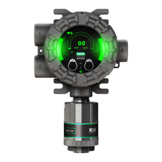
Page 7: Description
These are used to signal normal operating conditions, fault conditions and alarm conditions. The ULTIMA X5000 will go into “Eco-Mode” after 3 minutes of no interaction and if not in an alarm condition. While in Eco-Mode, the main display will power down and the status LED's will remain illuminated to determine that the device is not in an alarm condition. -
Page 8: No Tool Interface
The ULTIMA X5000 can be ordered with Bluetooth communication. Using the X/S Connect App on an appropriate smart phone or tablet, you are able to interface with the ULTIMA X5000 in a larger and more user friendly setting. Connecting via Bluetooth enables communication with trans- mitter up to 70 feet (21 m) away. -
Page 9: Retrofit Installations
XCell sensors without needing to power down the instrument. For added convenience, the ULTIMA X5000 comes with Swap Delay enabled by default; a feature that gives users a 2 minute window to change sensors without triggering a fault condition. For more information on SafeSwap and Swap Delay, see section 4.2.1. -
Page 10: Housing
Description Housing The ULTIMA X5000 comes in 316 Stainless Steel for the highest corrosion resistance. Both ¾” NPT and M25 conduit entries are available. To attach a sensor to an M25 housing, an M25 adapter is required and will be included with the shipment. An integral surface mount bracket can be used to mount directly into the wall surface or used with a U-Bolt for mounting to a 2”... -
Page 11: Installation
For ULTIMA X5000 Digital Sensors marked Class II or III and installed in a Class II or III hazardous location, the atmosphere must be free of dust or fibers or filings and the power removed from the unit before the sensor cap can be removed from the housing. -
Page 12: Product Installation Check List
Optimum sensor placement will depend on the surrounding processing equipment, such as pipes, valves, or turbines. MSA offers a gas and flame mapping service that systematically evaluates potential sources of leaks and recommends detector quantity and placement to create the most effective detection system. -
Page 13: Sensor Orientation
Installation 3.4.3 Sensor Orientation Sensor orientation will depend on the sensor type. If mounting an ULTIMA XIR PLUS sensor, whether locally on the transmitter or via remote junction box, the sensor should be mounted hori- zontally. If the ULTIMA XIR PLUS sensor is not mounted horizontally, the sensor will be prone to more frequent beam blocking issues due to accumulated dust and condensation on the surface of the ULTIMA XIR PLUS sensor. -
Page 14: Connecting Sensor To Transmitter Housing Or Remote Junction Box
If using a second sensor, connect it to the “Sensor 2” position. CAUTION! If only using one sensor, and it is connected to “Sensor 2” position, the ULTIMA X5000 will enter Sensor Missing fault. See Disable Sensor in section 4.2.2 for details on how to clear this fault. - Page 15 Grounding Sensor to Transmitter Housing Verify the sensor connector is firmly seated on the terminal board. Attach the sensor's ground to either of the grounding screws inside the ULTIMA X5000 housing. Replace the board stack legs into the four depressions in the housing. Push firmly on the board stack where indicated (see Fig.
-
Page 16: Integrated Mounting Points
Installation 3.4.5 Integrated Mounting Points The ULTIMA X5000 transmitter can be surface mounted without any additional brackets using the integrated mounting tabs. Fig. 10 Internal Mounting Tabs (not compatible with ULTIMA XIR PLUS Sensors) An supplementary mounting bracket is required for surface mounting the ULTIMA X5000 with an attached ULTIMA XIR PLUS sensor. -
Page 17: 2" (50.8 Mm) Pipe Mount
The integrated mounting tabs on the device housing can be mounted to a 2" (50,8 mm) pipe using a standard U-bolt. MSA provides U-bolts as an optional accessory (Part Number 10179873), however any 2” (50.8 mm) pipe U-bolt rated for the weight and dimensions of the ULTIMA X5000 can be used. -
Page 18: Duct Mount
Installation 3.4.8 Duct Mount Duct mount kits are available for monitoring atmosphere inside flat or round ducts. Round duct mount kits are available for small ducts 12-20" (305-508 mm) in diameter (Part Number 10179124) and large ducts 20-40" (508-1016 mm) in diameter (Part Number 10179321). The flat duct mount (Part Number 10176947) is universal for flat ducts. -
Page 19: Mounting With A Sunshield
Installation 3.4.9 Mounting with a Sunshield A sunshield is recommended to protect the ULTIMA X5000 from direct sun light (Part Number 10180254). The sunshield can be used in any of the mounting configurations. Fig. 16 Sunshield with Wall Mounting Bracket Fig. -
Page 20: Mounting With An Sm5000 Sampling Module
Installation 3.4.10 Mounting with an SM5000 Sampling Module An aspirated (PN 10058101) and a DC pump model are available for use with the X5000 with either digital or XIR sensors. For more information on mounting requirements and use with SM5000 sampling modules, see the SM5000 operating manual(s). Fig. -
Page 21: Installing A Remote Sensor Junction Box
If the remote sensor is not easily accessed, it is best practice to install tubing that can be used to apply calibration gas from the device display. Route the tubing to the ULTIMA X5000 Gas Monitor, ensuring that there are no kinks, leaks or other obstructions. Secure this tubing near the monitor. -
Page 22: Electrical Power Connections
• For ULTIMA X5000 Digital Sensors marked Class II or III and installed in a Class I or III hazardous location atmosphere must be free of dust or fibers/flyings and the power removed from the unit before the sensor cap can be removed from the housing. Failure to follow this warning can result in the ignition of a hazardous atmosphere. -
Page 23: Power Load Requirements And Maximum Mounting Distances
Maximum Wire Length to Main Transmitter with Single Sensor, Imperial Units When sizing a system's 24 V supply, a 1 A inrush current with a 1 ms duration should be considered for each ULTIMA X5000 on the power supply. Assumes transmitter was ordered with relays... - Page 24 Maximum Wire Length to Main Transmitter with Single Sensor, Metric Units When sizing a system's 24 V supply, a 1 A inrush current with a 1 ms duration should be considered for each ULTIMA X5000 on the power supply. Assumes transmitter was ordered with relays...
- Page 25 Maximum Wire Length to Main Transmitter with Two Sensors, Imperial Units When sizing a system's 24 V supply, a 1 A inrush current with a 1 ms duration should be considered for each ULTIMA X5000 on the power supply. Assumes transmitter was ordered with relays...
- Page 26 Maximum Wire Length to Main Transmitter with Two Sensors, Metric Units When sizing a system's 24 V supply, a 1 A inrush current with a 1 ms duration should be considered for each ULTIMA X5000 on the power supply. Assumes transmitter was ordered with relays...
- Page 27 Maximum Wire Length to Main Transmitter with Two Remoted Sensors, Imperial Units When sizing a system's 24 V supply, a 1 A inrush current with a 1 ms duration should be considered for each ULTIMA X5000 on the power supply. Assumes transmitter was ordered with relays Max.
-
Page 28: Instructions For Power And Analog Output
Using shielded cable is recommended. The cable shield should be terminated internal to the instrument enclosure using the crimp terminal provided (see Fig. 26). Remove the ULTIMA X5000 cover by turning counter-clockwise. Pull on the metal bail, removing electronics, to expose sensor and power connections. - Page 29 Installation Fig. 26 Connecting Power and Grounding Cable Attach the connector to the board stack, making sure the appropriate wires are in the correct terminals. (10) Connect HART wires (for optional local HART port). (11) Connect an XCell or XIR PLUS sensor using the green connector. Sensor wires are already connected as shown on the cover plate (see Fig.
- Page 30 Care must be taken to insure the X5000 inside glass surface is free of smudges/dirt and grease. Dirt and grease can interfere with the touch interface of the display. ULTIMA X5000 Installation Outline Drawings Model Document No.
-
Page 31: Relay And Power Connections
3.6.5 Relay and Power Connections Relay Board Stack Overview The ULTIMA X5000 can be purchased with three relays. Two of the relays can be configured for either de-energized (default) or energized and latching or non-latching (default). The third relay is a dedicated fault relay. - Page 32 The Fault relay state cannot be reconfigured. Relay Energy State and Terminal Connections The ULTIMA X5000 relays can be selected as energized or de-energized on the device. The default configuration is the De- Energized state. The preferred relay energy state should be deter- mined before making connections.
-
Page 33: Operation
See section 5 for calibration details. Settings The ULTIMA X5000 is a tool free transmitter. The two EZ touch buttons on the face of the display can be used to navigate through the menu structure. The buttons are designed for use with fingers with a “press”... -
Page 34: Instrument Settings
Operation 4.2.1 Instrument Settings The following settings are saved to the device memory and will not change if the sensor type is changed. Scroll to Settings. Select Instrument. Select to enter the menu. Setting Default Menu 1 Options Menu 2 Options De-energized Relay State De-energized Relay 1... - Page 35 Operation Setup Relay State for Energized or De-Energized Relays 1 and 2 are default De-energized. Relay 3 is a fault relay that is set to Energized and cannot be changed. To set Alarm Relay State: Scroll to Settings. Select Instrument. Select Relay Setup.
- Page 36 Operation Fig. 32 Horn Mode Relay Map and Alarm Actuation Analog Output Settings for Fault Conditions Analog outputs can be set to 3.5 mA and 1.25 mA with HART, or to custom output values as listed in Tab. 12. Output settings for oxygen sensors are not configurable. The Maintenance analog output is used during start up, Reset Main Unit, and Controller Data Reset.
- Page 37 Operation Enable Bluetooth Communications Every ULTIMA X5000 ordered with Bluetooth comes with the communications enabled by default. Bluetooth must be enabled for any Bluetooth functions to operate. A compatible Bluetooth host with the X/S Connect app is needed for connection.
- Page 38 If a sensor is not reconnected after the 2 minute window, the ULTIMA X5000 will enter a “Sensor Missing” fault condition. All XCell Sensors have SafeSwap and do not need to be disconnected from power while changing sensors.
- Page 39 The password entry screen defaults to 0000 and is disabled by default. When the password is enabled, a lock icon will appear in the top right corner of the display. If the password is lost, call MSA Customer Service at 1-800-672-2222. To enable the password: Scroll to Settings.
- Page 40 French, Spanish, Portuguese, Italian, Dutch, Russian, Chinese, and German. The X/S Connect App is only available in English, and does not change when the display language on the ULTIMA X5000 is changed. To change the display language: Scroll to Settings.
-
Page 41: Sensor Settings
The unit will reboot, and the AO will go to the values entered for Maintenance. 4.2.2 Sensor Settings The following settings are saved to the ULTIMA X5000 so that if the sensor is replaced with the same sensor type (gas and range), the settings will remain the same. If a different sensor type and range is used to replace the previous sensor, the new sensor’s default settings will upload to... - Page 42 Operation Select Disabled, Increasing/Non-Latching, Increasing/Latching, Decreasing/Non-Latching, or Decreasing/Latching. Scroll and select Save. Span Value The span value is used to set the calibration point. The default span values are approximately half of the total range of the sensor as purchased (see Tab. 13). If the range is changed, the span value should also be changed to increase accuracy over the full scale range.
- Page 43 0 mA. By default, the ULTIMA X5000 has the Sensor 2 position disabled. If at any time a sensor is connected to a position that is disabled, the ULTIMA X5000 will automatically enable that sensor position.
- Page 44 Only one sensor can be disabled at a time. The transmitter will not allow both sensor positions to be disabled simultaneously. The ULTIMA X5000 only allows a sensor to be disabled after the transmitter has gone into Sensor Missing fault.
- Page 45 Operation XIR PLUS Increasing 5% Methane 0-100 0-20 0-100 1 Non-Latch (AA) XIR PLUS Increasing 4.4% Methane 0-100 0-20 0-100 1 Non-Latch (AC) XIR PLUS Increasing 2.1% Propane 0-100 0-20 0-100 1 Non-Latch (AB) XIR PLUS Increasing 1.7% Propane 0-100 0-20 0-100 1 Non-Latch...
- Page 46 Operation Alarm 1 Alarm 2 Display Unit Alarm 1 Alarm 2 Gas (Code) Range Default AO Default AO Resolution Default Default Default (mA) (mA) Carbon 0-100 Monoxide (10) Carbon 0-500 Monoxide (11) Carbon 0-1000 Monoxide (12) Carbon Monoxide H 0-100 Resistant (14) Catalytic Bead 5% Methane...
-
Page 47: Status Menu
Operation Status Menu The following settings can be viewed through Status Menu without a password, regardless of whether one is enabled. Scroll and select Status. Use ↓ to scroll through the list: • Tag # • Software Version • Sensor Type •... -
Page 48: Calibration
WARNING! Use zero gas when zeroing the ULTIMA X5000 transmitter if there is any possibility of background gas. Otherwise, improper calibration could occur. Always calibrate for the least sensitive gas or vapor (higher number category) expected to be measured. -
Page 49: Calibration Frequency
Calibration Calibration Frequency The frequency of calibration gas testing depends on the operating time, chemical exposure, and type of sensor. Especially in new installations or applications, it is recommended that the first sensors be calibrated more often to establish the sensor performance in this particular environ- ment. -
Page 50: Calibration Types: Zero Vs. Span
The XIR Plus sensor can be calibrated to a wide variety of gas compounds using either 0.1 % Propane, 0.6 % Propane, or 2.5 % Methane and MSA's gas table. See Tab. 21 for a complete list of gas compounds and corresponding tables and span values. -
Page 51: How To Zero Calibrate Xcell Sensors
Calibration How to Zero Calibrate XCell Sensors NOTICE If a password is enabled, you will not be able to proceed with the calibration without the password. To abort, press either button on the touchscreen or mobile application at any time during the zero calibration. -
Page 52: How To Calibrate Xcell Sensors
Calibration How to Calibrate XCell Sensors (See section 5.7 for calibrating oxygen sensors.) NOTICE If a password is enabled, the user will not be able to proceed with the calibration without the pass- word. To abort, press either button on the touchscreen or mobile application before Span Calibration begins. -
Page 53: How To Calibrate An Xir Plus Sensor
Ensure that the area has been cleared of gas before acknowledging the LOC Over Range and recalibrating the sensor. 5.10 Calibration Confirmation The ULTIMA X5000 Gas Monitor records the date of the last successful calibration. This date can then be displayed on the OLED display under the Status Menu. ULTIMA® X5000... -
Page 54: Maintenance
Repair or alteration of the device, beyond the procedures described in this manual or by anyone other than a person authorized by MSA, could cause the unit to fail to perform properly. Use only genuine MSA replacement parts when performing any maintenance procedures described in this manual. -
Page 55: Replacing An Xcell Sensor
Failure to follow this warning can result in the ignition of a hazardous atmo- sphere. For ULTIMA X5000 Digital Sensors marked Class II or III and installed in a Class II or III hazardous location, the atmosphere must be free of dust or fibers and filings and the power removed from the unit before the sensor cap can be removed from the housing. -
Page 56: Troubleshooting
Maintenance It is recommended that all other maintenance be performed at an MSA factory-authorized service center. Troubleshooting The following table lists all fault messages, their priority levels, and corrective actions required to resolve them. The faults are listed in alphabetical order. Lower priority messages are output only after the highest priority message is cleared. - Page 57 Maintenance Status LEDs Priority Display Message Description Resolution (G/Y/R) Indicates a hardware “Internal Circuit ON/ON/OFF failure on the main Replace the main PCBA. Fault” PCBA. Indicates the sensors lamp is not operating “Lamp Fault” ON/ON/OFF Replace the sensor. properly. (XIR PLUS sensors only) Recalibrate the sensor to get “Life and Health...
- Page 58 Maintenance Status LEDs Display Message Description Resolution Priority (G/Y/R) Indicates the sensors “Sensor Heater ON/ON/OFF heater is not working Replace the sensor. Fault” properly. Indicates the detec- “Sensor Internal 25-40 ON/ON/OFF tion of a hardware Replace the sensor. Fault” issue in the sensor. Indicates the sensor “Sensor Missing”...
- Page 59 Maintenance Status LEDs Display Message Description Resolution Priority (G/Y/R) Indicates that a Replace the sensor or sensor is returning an “Unknown Error” ON/ON/OFF update the main PCBA soft- unknown error condi- ware. tion. Acknowledge the fault to revert to the previous calibra- tion.
-
Page 60: Ordering Information
Failure to do so may seriously impair sensor and gas monitoring perfor- mance. Repair or alteration of the ULTIMA X5000 Gas Monitor, beyond the scope of these main- tenance instructions or by anyone other than authorized MSA service personnel, could cause the product to fail to perform as designed and persons who rely on this product for their safety could sustain serious personal injury or loss of life. -
Page 61: Accessories
ROUND DUCT MOUNT KIT, SMALL, ULTIMA X5000 10179124 ROUND DUCT MOUNT KIT, LARGE, ULTIMA X5000 10179321 Pipe Mount Kit, Universal 20-150 MM PIPE MOUNT, ULTIMA X5000/S5000 10176946 Pipe Mount Kit, 2" U-Bolt 2” PIPE MOUNT KIT, ULTIMA X5000 10179873 Sun Shield SUNSHIELD, ULTIMA X5000/S5000... -
Page 62: Appendix: Specifications
Appendix: Specifications Appendix: Specifications Combus- XIR PLUS XIR PLUS Sensor Options Toxics Oxygen tible Cata- Combusti- Carbon lytic bles Dioxide -40 °C to -40 °C to -40 °C to -40 °C to -40 °C to Operating Range +60 °C +60 °C +60 °C +60 °C +60 °C... - Page 63 Appendix: Specifications Transmitter Dimensions Fig. 35 ULTIMA X5000 Height & Width Fig. 36 Short Lid Depth Fig. 37 Deep Lid Depth Fig. 38 ULTIMA X5000 Width with XIR PLUS Sensor ULTIMA® X5000...
-
Page 64: Appendix: Calibration Guide For Additional Gases
Appendix: Calibration Guide for Additional Gases Appendix: Calibration Guide for Additional Gases The ULTIMA XIR PLUS sensor can be calibrated for a wide variety of combustible gas compounds. This information is only applicable for combustible XIR PLUS sensors and does not apply to CO and acetylene sensors. - Page 65 Appendix: Calibration Guide for Additional Gases ATO Code Compound Vol % for % LEL Table Cal Gas Span Value Acetaldehyde 0.1 % Propane 29 % Acetic Acid 0.6 % Propane 12 % Acetone 0.1 % Propane 20 % Acrolein 0.1 % Propane 59 % Acrylic Acid 0.6 % Propane...
- Page 66 Appendix: Calibration Guide for Additional Gases ATO Code Compound Vol % for % LEL Table Cal Gas Span Value Epichlorohydrin 0.6 % Propane 46 % Ethane 0.6 % Propane 25 % Ethanol 0.6 % Propane 31 % Ethyl Acetate 0.6 % Propane 60 % Ethyl Acrylate 0.1 % Propane...
- Page 67 Appendix: Calibration Guide for Additional Gases ATO Code Compound Vol % for % LEL Table Cal Gas Span Value Methyl Isobutyl 0.6% Propane Carbinol (MIBC) Methyl Isobutyl 0.6% Propane Ketone (MIBK) Methyl Methacrylate 1.7 0.6% Propane Methyl Propyl Ketone 0.6% Propane (MPK) Methyl tert-butyl 0.6% Propane...
-
Page 68: Appendix: General Certification Information
Appendix: General Certification Information Appendix: General Certification Information Refer to manual addendum (Part Number 10182779) for Certification Information. ULTIMA® X5000... -
Page 69: Appendix: Hart Specific Information
Appendix: HART Specific Information Appendix: HART Specific Information The ULTIMA X5000 Gas Monitor is available with an optional HART (Highway Addressable Remote Transducer) output communications protocol. With this option, the ULTIMA X5000 complies with HART Protocol Revision 7. All available status bytes are defined in the X5000 HART Specification found on the product CD. - Page 70 For local MSA contacts, please visit us at MSAsafety.com Because every life has a purpose...
Need help?
Do you have a question about the ULTIMA X5000 and is the answer not in the manual?
Questions and answers