Table of Contents
Advertisement
Quick Links
®
GASGARD
8 Monitor
instruction manual
In the U.S., to contact your nearest stocking location, dial toll-free 1-800-MSA-INST.
To contact MSA International, dial 1-412-967-3354.
© MINE SAFETY APPLIANCES COMPANY 2005- All Rights Reserved
Distributed by
MSA INSTRUMENT DIVISION
P.O. Box 427, Pittsburgh, Pennsylvania 15230
(L) Rev 4
10029332
Advertisement
Table of Contents

Related Manuals for MSA GASGARD 8


Summary of Contents for MSA GASGARD 8
- Page 1 ® GASGARD 8 Monitor instruction manual In the U.S., to contact your nearest stocking location, dial toll-free 1-800-MSA-INST. To contact MSA International, dial 1-412-967-3354. © MINE SAFETY APPLIANCES COMPANY 2005- All Rights Reserved Distributed by MSA INSTRUMENT DIVISION P.O. Box 427, Pittsburgh, Pennsylvania 15230...
- Page 2 " WARNING THIS MANUAL MUST BE CAREFULLY READ BY ALL INDIVIDUALS WHO HAVE OR WILL HAVE THE RESPONSIBILITY FOR USING OR SERVICING THE PRODUCT. Like any piece of complex equipment, the unit will perform as designed only if it is installed, used and serviced in accordance with the manufacturer’s instructions.
- Page 3 MSA Permanent Instrument Warranty 1. Warranty- Seller warrants that this product will be free from mechanical defect or faulty workmanship for a period of eighteen (18) months from date of shipment or one (1) year from installation, whichever occurs first, provided it is maintained and used in accordance with Seller’s...
-
Page 4: Table Of Contents
Installation ....... . 2-1 Mounting the Gasgard 8 Gas Monitor ......2-1 "... - Page 5 Table of Contents Figure 2-8. RS-485 Wiring Connection ......2-8 Chapter 3 Start-up and Operation ..... . 3-1 RS-485 Output .
- Page 6 Table of Contents To Access the % LEL OVERRANGE <WArn> Reset: ....3-11 To Access the Configuration <ConF> Mode: ..... . 3-11 Figure 3-3.
-
Page 7: General Information
Section 1 General Information Introduction The Gasgard 8 Gas Monitor is designed for remote monitoring of up to eight input sensors (two or three-wire 4-20 mA). Calibration of the sensor is performed at the sensor location and does not require calibration adjustments at the monitor, reducing the personnel required for calibration. -
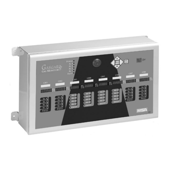
Page 8: Front Panel Features
Chapter 1, General Information Figure 1-1. Front Panel Front Panel Features Display - Four digit, 1/2-inch readout indicates remote sensor gas concentration readings. Power-On - Green LED indicates unit is powered ON. Alarms (AL1 through AL4) - Four red LEDs indicate when gas concentrations exceed alarm level setpoints. - Page 9 • Buzzer status. Sensor ID Tag Area - Use this area to identify the sensor type connected to the Gasgard 8 Monitor. Table 1-1. Gasgard 8 Gas Monitor General Specifications ELECTRICAL CHARACTERISTICS AC Voltage 100 - 240 VAC, 47 - 63 Hz...
-
Page 10: Chapter 2 Installation
The housing is a general-purpose enclosure and is not suitable for hazardous locations. " CAUTION Make sure the Gasgard 8 Monitor unit is not blocked; otherwise front panel lights and controls will be obscured from view. 2. Using four 1/4 or 20 mm mounting screws, mount the Gasgard 8 Monitor to a wall or suitable structure. -
Page 11: Caution
Chapter 2, Installation 2. To connect the Gasgard 8 Monitor to the power source, connect AC, ACN and GND terminals of the AC connector to the power source in accordance with FIGURE 2-1. "! CAUTION Improper application of the primary power to the system may cause damage to the unit. -
Page 12: Optional Dc Power Wiring Connection
Chapter 2, Installation Optional DC Power Wiring Connection 1. Prior to wiring the DC Power Supply, disconnect the two wires from the AC Power Supply from Terminal IN OV and +ALIM, located on the inside front panel. 2. Connect the two wires from the external 24 VDC Power Supply to the same terminal IN OV (negative) and +ALIM (+24 VDC). -
Page 13: Sensor Wiring Connection
Chapter 2, Installation Sensor Wiring Connection The Gasgard 8 Monitor is capable of taking a two-wire or three-wire loop 4-20 mA sensor. Refer to the sensor manual to determine: • Optimal sensor placement • Required wire size • Number of conductors required for proper operation. -
Page 14: Relay Wiring Connection
Chapter 2, Installation Relay Wiring Connection The four alarm relays and the one fault relay are single-pole, double-throw and can be jumper-configured from within the unit. Figure 2-4 identifies jumper locations for normally-opened and normally-closed configurations on the universal relay module, each channel of which is normally energized (fail-safe). -
Page 15: 4-20 Ma Output Wiring Connection
Chapter 2, Installation 4-20 mA Output Wiring Connection Each channel card contains one 4-20 mA output. Wiring is shown in FIGURE 2-5. Figure 2-5. 4-20 mA Output Wiring Connection... -
Page 16: Remote Device Wiring Connection
Figure 2-6. Remote Device Wiring Connection Serial Link Module Wiring Connection The Gasgard 8 Monitor has the capability of interfacing with either an RS-232 connection (printer) or an RS485 connection (superior/JBus). Wiring is shown in FIGURE 2-7 and FIGURE 2-8. - Page 17 Chapter 2, Installation Figure 2-7. RS-232 Wiring Connection Figure 2-8. RS-485 Wiring Connection...
-
Page 18: Start-Up And Operation
Chapter 3 Start-up and Operation RS-485 Output The Gasgard 8 Controller uses an RS-485 serial interface with Modbus protocol. To communicate to the RS-485 output via a computer interface, an isolated RS-485 converter should be used. The baud rate is 1200 or 9600 baud with RTU format sent. Each byte has eight bits with no parity and two stop bits. -
Page 19: Internal Buttons And Features
• User Mode <USER> which allows the operator to perform operations and access limited features. 3. Each channel of the Gasgard 8 Monitor must be configured for: • Sensor range • Alarm level • Alarm upscale or downscale •... -
Page 20: To Access The Configuration
<BAD> for an incorrect entry. • The password can be modified by using the <CODE> feature. 2. Configuration of the Gasgard 8 Monitor is performed by selecting through the programming flowchart (FIGURE 3-2). 3. Use the <SCROLL DOWN> and <SCROLL UP> buttons on the keypad to access the software options.Mode - Page 21 Chapter 3, Start-up and Operation Figure 3-2. Factory Mode Programming Flowchart...
-
Page 22: To Access The Sensor
Chapter 3, Start-up and Operation 2. Use the <SCROLL LEFT> and the <SCROLL RIGHT> buttons to copy one channel’s configuration onto the current channel being configured. • All configurations are copied (sensor range, alarm level, latching/non-latching, de-energized/energized, etc.). • The choice is confirmed by pressing the <ACK/VALID> button or rejected by pressing the <ESC/TEST>...Mode - Page 23 Chapter 3, Start-up and Operation 2. Use the <SCROLL UP> or <SCROLL DOWN> buttons to configure each of the four alarm levels (A1 through A4). • The choice is confirmed by pressing the <ACK/VALID> button or rejected by pressing the <ESC/TEST> button. •...
-
Page 24: To Access The Buzzer
Chapter 3, Start-up and Operation • Latching Mode requires the <ACK/VALID> button be pressed after an alarm condition has passed to de-activate relays, LEDs and the horn. • Half-Latching Mode allows the relays and horn to de-activate after an alarm condition has passed; however, alarm LEDs must be de-activated by pressing the <ACK/VALID>...Mode -
Page 25: To Access The Date
Chapter 3, Start-up and Operation • The choice is confirmed by pressing the <ACK/VALID> button or rejected by pressing the <ESC/TEST> button. To Access the Date <dAtE> Mode: 1. Select <dAtE> and press the <ACK/VALID> button. 2. Use the <SCROLL UP> and <SCROLL DOWN> buttons to access the time, date, and year.Mode -
Page 26: To Access The Code
Chapter 3, Start-up and Operation NOTE: Enter the four-digit year in the same manner as the password was input to access the factory mode. • The choice is confirmed by pressing the <ACK/VALID> button or rejected by pressing the <ESC/TEST> button. To Access the Code <CodE>...Mode -
Page 27: To Access The Printer
Chapter 3, Start-up and Operation To Access the Printer <INp> Mode: 1. Select <INp> and press the <ACK/VALID> button. 2. Select the choice of printer language by using the <SCROLL UP> and <SCROLL DOWN> buttons. • Choices include French (Fr), English (EnGl), Spanish (SPAn), German (DEut), and Italian (ItAL).Mode -
Page 28: To Exit The Factory
<BAD> for an incorrect entry. • The password can be modified by using the <CODE> feature. 2. Configuration of the Gasgard 8 Monitor is performed by selecting through the programming flowchart (FIGURE 3-3). To Access % LEL OVERRANGE <WArn> Reset: 1.Mode - Page 29 Chapter 3, Start-up and Operation Figure 3-3. User Mode Programming Flowchart 3-12...
-
Page 30: To Access The Channel Inhibit
Chapter 3, Start-up and Operation 2. Use the <SCROLL RIGHT> and the <SCROLL LEFT> buttons to initiate configuration of the remaining channels (n2 through n8). 3. Press the <ACK/VALID> button to configure a specific channel. To Access the Channel Inhibit <Inh> Mode: 1.Mode -
Page 31: To Access The Buzzer
Chapter 3, Start-up and Operation however, alarm LEDs must be de-activated by pressing the <ACK/VALID> button. • Non-Latching Mode allows for automatic de-activation of relays, LEDs and the horn after an alarm condition has passed. • The choice is confirmed by pressing the <ACK/VALID> button or rejected by pressing the <ESC/TEST>...Mode -
Page 32: To Access The Code
Chapter 3, Start-up and Operation • The choice is confirmed by pressing the <ACK/VALID> button or rejected by pressing the <ESC/TEST> button. To Access the Code <CodE> Mode: 1. Select <CodE> and press the <ACK/VALID> button. • The Password Code is listed. 2.Mode -
Page 33: Performing A Configuration Review
Chapter 3, Start-up and Operation • The software version and serial number of the unit is displayed. • All display LED characters and all fault and alarm LEDs are activated. NOTE: During this test, all alarms and channel displays are still operating in measure mode. - Page 34 Chapter 3, Start-up and Operation Table 3-3. Parts List PART PART NO. RS 232 Interface Card 10029957 RS485 Modbus RTU Interface Card 10029958 Channel Upgrade Kit includes one Channel PCB with Display 10035784 and Relay Module Channel PCB 10029955 Relay Module 10029956 Blank Panel 10029959...
Need help?
Do you have a question about the GASGARD 8 and is the answer not in the manual?
Questions and answers