
Subscribe to Our Youtube Channel
Related Manuals for THORLABS APF503


Summary of Contents for THORLABS APF503
- Page 1 APF503, APF705 and APF710 Amplified Piezo Actuators User Guide Original Instructions HA0375T...
-
Page 2: Table Of Contents
APF503, APF705 and APF710 Amplified Flexure Piezo Actuators Contents Chaper 1 Overview ..................... 1 1.1 Introduction ..................1 Chaper 2 Safety ......................2 2.1 Safety Information ................2 2.2 General Warnings ................2 Chaper 3 Installation ....................4 3.1 Storage Precautions ................4 3.2 Mechanical Installation .............. -
Page 3: Chaper 1 Overview
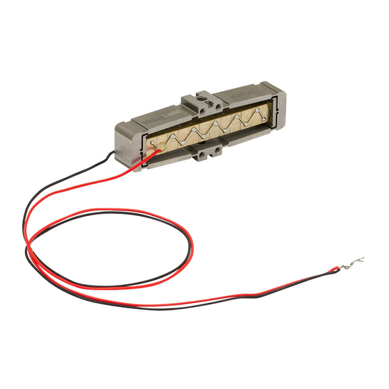
The flexure structure also offers various options for fixing other components and integration into third party equipment. The actuators offer flexibility in assembly and a minimised footprint. Fig. 1.1 APF503, APF705 and APF710 amplified piezo actuators Page 1... -
Page 4: Chaper 2 Safety
APF503, APF705 and APF710 Amplified Flexure Piezo Actuators Chapter 2 Safety 2.1 Safety Information For the continuing safety of the operators of this equipment, and the protection of the equipment itself, the operator should take note of the Warnings, Cautions and Notes throughout this handbook and, where visible, on the product itself. - Page 5 Chapter 2 Safety Warning Piezo actuators are driven by high voltages. Voltages up to 150V may be present at the connector. This is hazardous and can cause serious injury. Appropriate care should be taken when using this device. Persons using the device must understand the hazards associated with using high voltages and the steps necessary to avoid risk of electrical shock.
-
Page 6: Chaper 3 Installation
APF503, APF705 and APF710 Amplified Flexure Piezo Actuators Chapter 3 Installation 3.1 Storage Precautions Warning Piezos can store and release large amounts of energy and should be handled with caution. To prevent charge build up, piezos must be stored with the high voltage wires (red and white) joined together (short circuit). -
Page 7: Electrical Connections
Chapter 3 Installation Negative wire (black) (-30V limit) Positive wire (red) ( +150V limit) Notch (4 Places) to accept a key feature on the mating part M2.5 (qty 1 top and bottom) max mounting screw length 3.0 mm (0.118”) M1.6 (qty 4 both sides) max mounting screw length 3.4 mm (0.134”) Fig. -
Page 8: Maximum External Preload Inserted By The Application
APF503, APF705 and APF710 Amplified Flexure Piezo Actuators voltage and the white wire (APF7 series) or black wire (APF5 series) should be grounded. Note Typically, the black/white wire should be used as a ground reference (e.g. connecting to chassis of controller), and a bipolar power supply used to drive the red wire -30V to 150V. - Page 9 APF710 55 N 20 N Fixed 25 N APF705 20 N Fixed APF503 10 N 10 N Fixed Warning Preloads in excess of the recommended values can damage the actuator. Fig. 3.3 External preload values Rev C Aug 2019 Page 7...
-
Page 10: Chaper 4 Operation
Any residual charge remaining in the piezo stack should be discharged. For a complete tutorial on driving the actuator using the Thorlabs range of controllers, see the handbook for the appropriate controller. Basic steps in controlling the actuator using a Thorlabs controller are as follows: 1) Fit the actuator to the relevent stage or mount. -
Page 11: How The Actuator Moves With Voltage
Up -30V Max Down +150V Max Bottom face fixed Fig. 4.1 APF503, APF705 and APF710 actuator movement Furthermore, despite the very high resolution of piezoelectric actuators (the actual resolution achived will depend on the controller used), an inherent problem is the significant amount of hysteresis they exhibit, (i.e., the tendency of the actuator to... -
Page 12: Chaper 5 Specification
APF503, APF705 and APF710 Amplified Flexure Piezo Actuators Chapter 5 Specification 5.1 General Specifications Parameter APF503 APF705 APF710 Variance Operating Voltage -30V to 150V Travel (0 to 150V) 310 µm 440 µm 1150 µm ±15% Travel (-30V to 150V) 390 µm 560 µm... - Page 13 Chapter 5 Specification Off-axis (asymmetric) loading in relation to the top mounting hole axis will affect the resonant frequency (see Fig. 5.1 and Fig. 5.2). Fig. 5.1 Effect of assymetric loading on resonance mode, linear v angular Page 11 Rev C Aug 2019...
- Page 14 APF503, APF705 and APF710 Amplified Flexure Piezo Actuators Linear Angular Pitch Fig. 5.2 Definition of linear and angular resonance modes Page 12...
- Page 15 Chapter 5 Specification *with assymetric loading in relation to the top mounting hole axis Fig. 5.3 APF503 resonant frequency v load *with assymetric loading in relation to the top mounting hole axis Fig. 5.4 APF705 resonant frequency v load Page 13...
- Page 16 APF503, APF705 and APF710 Amplified Flexure Piezo Actuators *with assymetric loading in relation to the top mounting hole axis Fig. 5.5 APF710 resonant frequency v load Page 14...
-
Page 17: Chaper 6 Thorlabs Worldwide Contacts
Waste treatment is your own responsibility. "End of life" units must be returned to Thorlabs or handed to a company specializing in waste recovery. Do not dispose of the unit in a litter bin or at a public waste disposal site. - Page 18 www.thorlabs.com...
Need help?
Do you have a question about the APF503 and is the answer not in the manual?
Questions and answers