Table of Contents
Advertisement
Quick Links
Advertisement
Table of Contents

Subscribe to Our Youtube Channel
Related Manuals for R.V.R. Elettronica TCP/IP-INT-TEX


Summary of Contents for R.V.R. Elettronica TCP/IP-INT-TEX
- Page 1 TCP/IP-INT-TEX User Manual Volume 1 Manufactured by Italy...
- Page 2 Reason Editor 28/09/2007 First Edition J. H. Berti TCP_IP-INT-TEX - User Manual Version 1.0 © Copyright 2007 R.V.R. Elettronica SpA Via del Fonditore 2/2c - 40138 - Bologna (Italia) Telephone: +39 051 6010506 Fax: +39 051 6011104 Email: info@rvr.it Web: www.rvr.it...
-
Page 3: Table Of Contents
TCP/IP-INT-TEX Table of Contents Preliminary Instructions Warranty First Aid 3.1 Electric shock treatment 3.2 Treatment of electric burns Unpacking 4.1 General Description Installation and configuration procedure 5.1 Preparation 5.2 First Power-On and Set-Up 5.3 Management Software 6. External Description 6.1 Front Panel 6.2 Rear Panel... - Page 4 TCP/IP-INT-TEX This page was intentionally left blank Rev. 1.0 - 28/09/07 User Manual...
-
Page 5: Preliminary Instructions
Operating frequency, transmitter power and other characteristics of the transmission system are subject to restrictions as specified in the licence. R.V.R. Elettronica SpA shall not be liable for injury to persons or damage to property resulting from improper use 2. Warranty or operation by trained/untrained and qualified/unqualified persons. -
Page 6: First Aid
• Loosen the victim’s clothing and have him/her lie down. R.V.R. Elettronica SpA Via del Fonditore, 2/2c • Call for medical help as soon as possible. 40138 BOLOGNA ITALY Tel. -
Page 7: Unpacking
The TCP/IP-INT-TEX connects an exciter of the TEX-LCD series preset for the telemetry through RS232 serial port. The TCP/IP-INT-TEX uses a 16bit DSP, that is the ideal solution to adjust the device to the specific connection needs, it also implements the protocols to exchange data through the Internet, such as ARP & DHCP to assign IP addresses, or like the conformity to RFC for TCP/IP applications (such as HTTP, FTP server or e- mail). -
Page 8: Preparation
TCP/IP-INT-TEX Installation and configuration procedure This section provides a step-by-step description of device installation and configuration procedure. Follow these procedures closely upon first power-on and each time any change is made to general configuration, such as when a new transmission station is added or the equipment is replaced. Once the desired configuration has been set up, no more settings are required for normal operation; at each power-up (even after an accidental shutdown), the device defaults to the parameters set during the initial configuration procedure. -
Page 9: Installation And Configuration Procedure
TCP/IP-INT-TEX Note : If you intend to connect it directly to a PC, it is necessary to use a crossover ethernet cable. This is a basic prerequisite to ensure equipment correct operation. 3) Connect the network cable to the relevant POWER connector on TCP/IP interface. -
Page 10: Management Software
TCP/IP-INT-TEX 2) If the User Name and the Password have not been entered and saved yet, and if no changes were made to access modes, enter RVR and RVR to enter as administrator (if access data were modified, enter the new User Name and Password). Then click on Login. Note : To enter as user, type user and user into User Name and Password fields. - Page 11 TCP/IP-INT-TEX To enter in one of the sub-menus, select the name and then click on item to enter. To go back to MAIN menu, just click on RVR logo at top left of all sub-menus. If user tries to enter a sub-menu with no prior login, or after a certain period of...
- Page 12 TCP/IP-INT-TEX 5.3.1 Device Menu Values found here are “live readings”, and as such they can not be modified. This page shows the user the data of the exciter connected to the TCP/IP interface: Device Status Present Model Hardware Software Module connected Analog inputs Analog outputs Digital inputs Digital outputs Generic I/O Menu 4 Status Shows exciter connection state.
- Page 13 TCP/IP-INT-TEX 5.3.2 Status Menu Values found here are “live readings”, and as such they can not be modified. To change power setting use the Set Device (chapt. 5.3.3) after logging in as administrator. This page shows the user the data of the exciter connected to the TCP/IP...
- Page 14 TCP/IP-INT-TEX % Power Out Shows power setting efficiency. Foldback Shows the triggered status of the foldback function (automatic reduction of output power). Ext R.F. Mute Shows the status of power inhibition by an interlock signal. Unlock Shows the status of lock at frequency set by PLL. 5.3.3 Device Setting Menu Note : Access to this menu and modification of these parameters are only possible after login with administrator rights.
- Page 15 TCP/IP-INT-TEX Frequency Remote adjustment of exciter frequency. This value, in MHz, can be modified according to one’s own band in 0.1 MHz steps. % Power Out Remote adjustment of exciter power. This value, in %, can be modified in the range 0 to 100, in steps of 1%. 5.3.4 Active alarms Values found here are “live readings”, and as such they can not be modified.
- Page 16 TCP/IP-INT-TEX 5.3.5 Network settings Note : Access to this menu and modification of these parameters are only possible after login with administrator rights. This page not only shows the user the information about the TCP/IP interface network connection, but also allows setting various parameters.
- Page 17 TCP/IP-INT-TEX Subnet Mask Shows and sets the subnet mask, necessary for the computer that must communicate with another IP address to know if it should route packages toward the gateway of its local network or use the address of the receiver local network.
- Page 18 TCP/IP-INT-TEX Password Shows and sets password for enabling sending messages. Port Shows and sets the port used by TCP transmission protocol. Sender Address Shows and sets the transmission address used for sending messages. Domain name Shows and sets domain name. 5.3.5.3 POP3 menu...
- Page 19 TCP/IP-INT-TEX 5.3.6 General settings Note : Access to this menu and modification of these parameters are only possible after login with administrator rights. This page not only shows the user the information about the exciter connected to the TCP/IP interface, but also allows setting various parameters.
- Page 20 TCP/IP-INT-TEX Response timeout Shows and sets waiting time for receiving the response frame for the serial protocol. Uart Baud Shows and sets serial protocol speed. 5.3.6.2 Alarms menu General settings Run time DEVICE Enable alarms ALARMS SECURITY Enable send Mail Enable Recive Mail Destination 1 Software@rvr.it...
- Page 21 TCP/IP-INT-TEX 5.3.6.3 Security menu General settings Run time DEVICE Enable Login ALARMS SECURITY User name (Manut.) Password (Manut.) User name (User) user Password (User) Update Menu 13 This page allows configuration of the access to TCP/IP interface via WUI. Enable login Enables (0) or disables (1) access to the menus by means of the login page.
- Page 22 TCP/IP-INT-TEX 5.3.7 Commands menu This menu allows you to logout from WUI. Furthermore, using the Reset item, at bottom right of this menu, it is possible to restore software factory settings (back- up). Commands RESET Reset the software of the interface and restart it...
-
Page 23: External Description
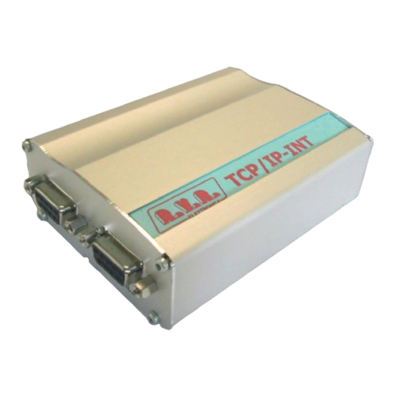
TCP/IP-INT-TEX 6. External Description This section describes the components found on the front and rear panel of TCP/ IP-INT-TEX. 6.1 Front Panel Figure 6.1 [1] SERIAL 1 DB9 connector for interface to exciter. [2] SERIAL 2 Not used - Reserved for future implementations. -
Page 24: Connector Pinouts
TCP/IP-INT-TEX 6.3 Connector Pinouts 6.3.1 RS232 Type: Female DB9 6.3.2 POWER Type: Female Microfit V+ (5-30VDC, power input approx 200mA) 20 / 22 Rev. 1.0 - 28/09/07 User Manual... -
Page 25: Technical Specifications
TCP/IP-INT-TEX 7. Technical Specifications 7.1 Electrical features General specifications Power supply 5÷30 VDC with Microfit connector Dimensions 95 x 72 x 32 mm Operating temperature 0 °C to +50 °C Hardware Power supply 5÷30 VDC with Microfit connector Input/Output 1 DB9 connector, for serial communication RS232 up to 230kbps Input/Output 2... - Page 26 TCP/IP-INT-TEX This page was intentionally left blank 22 / 22 Rev. 1.0 - 28/09/07 User Manual...
Need help?
Do you have a question about the TCP/IP-INT-TEX and is the answer not in the manual?
Questions and answers